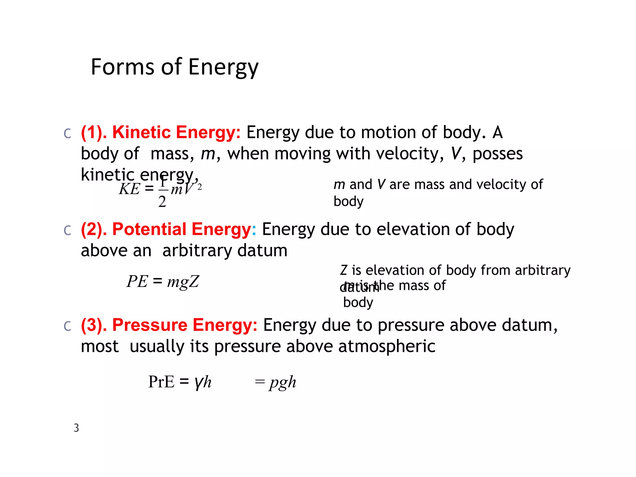
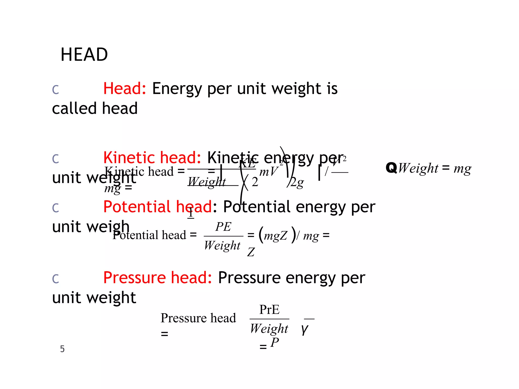
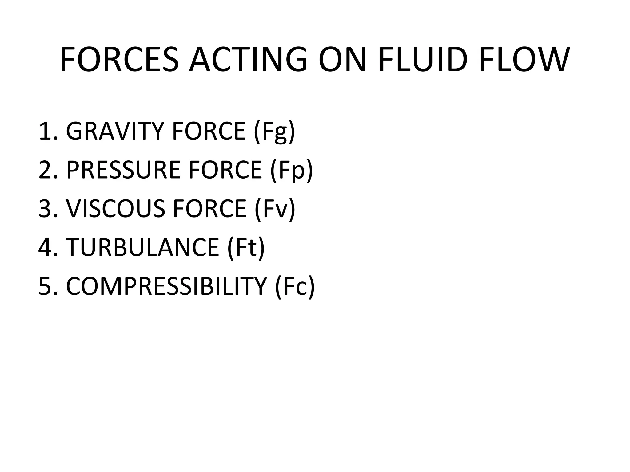
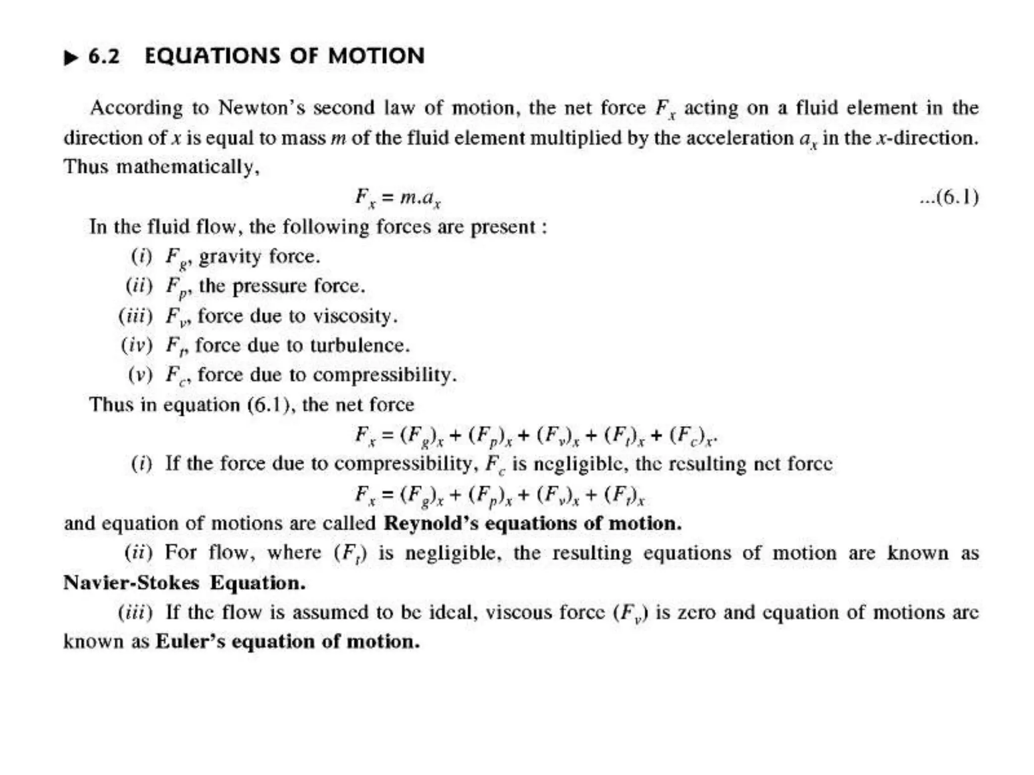
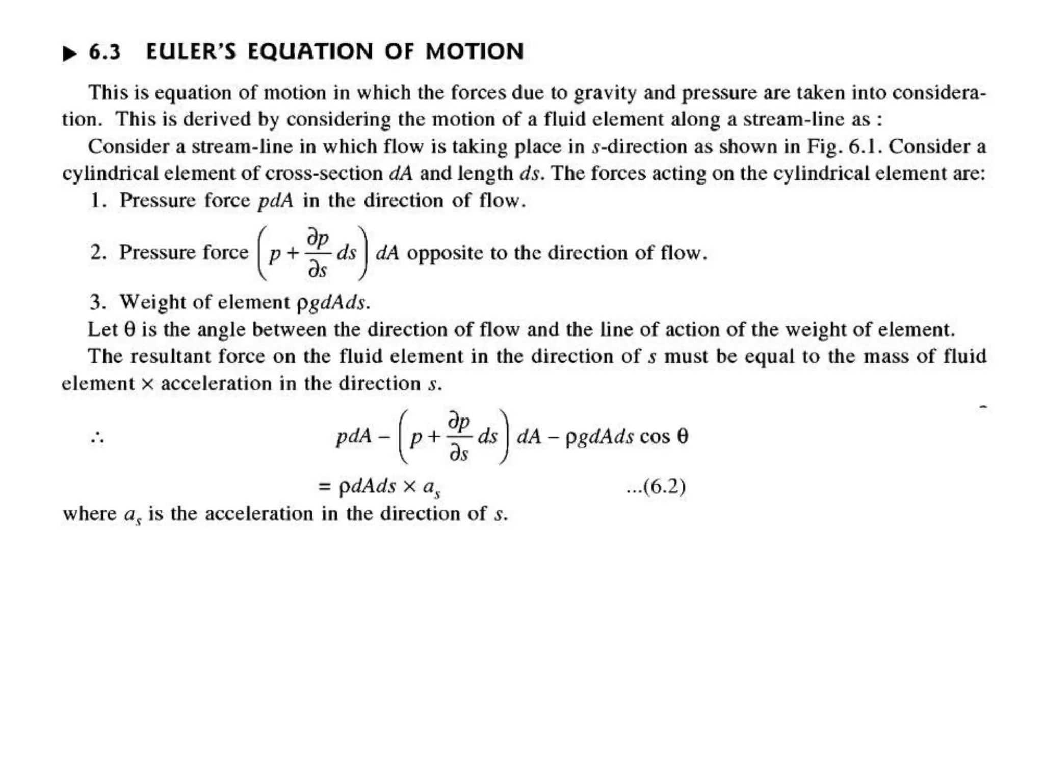
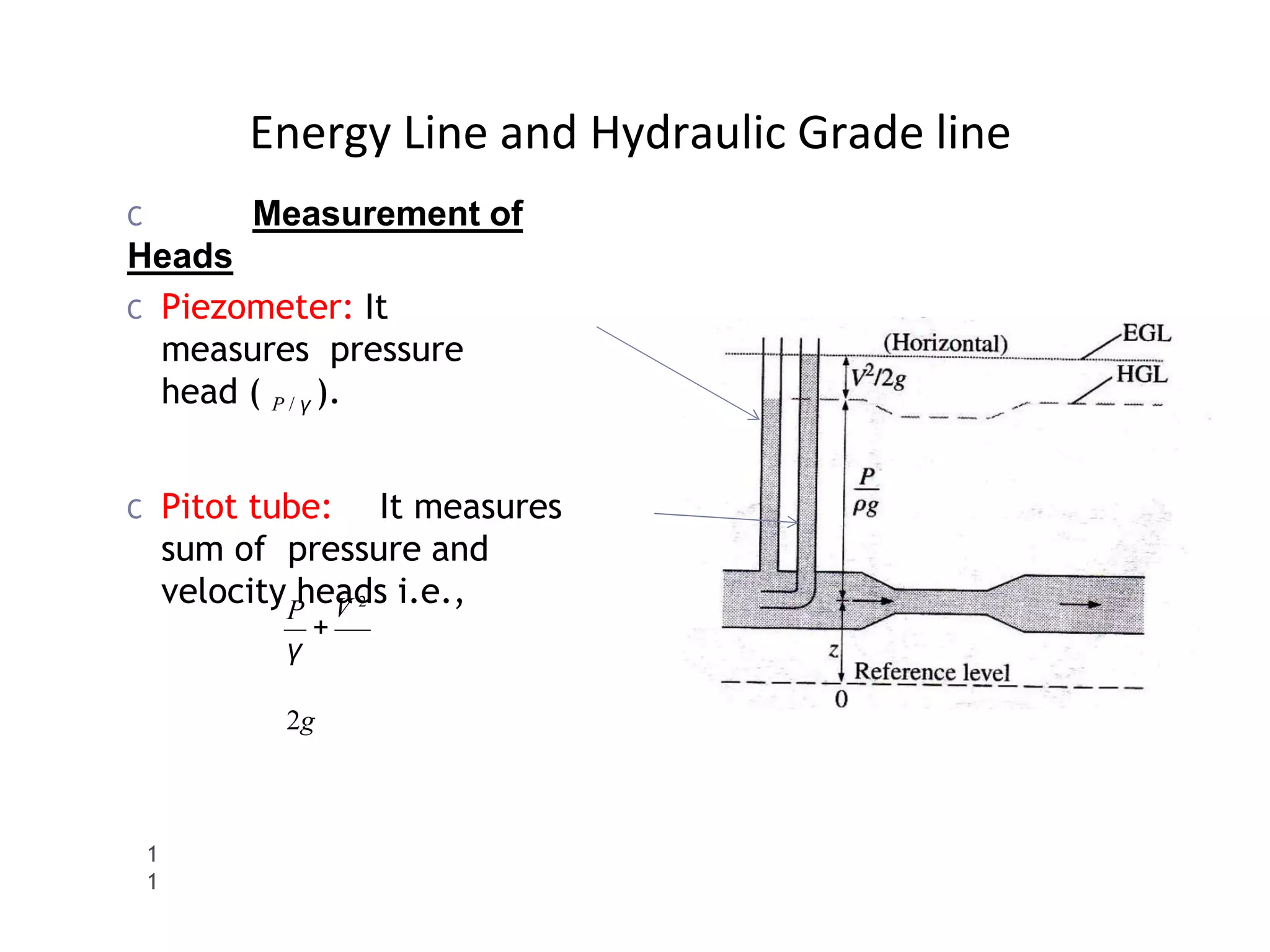
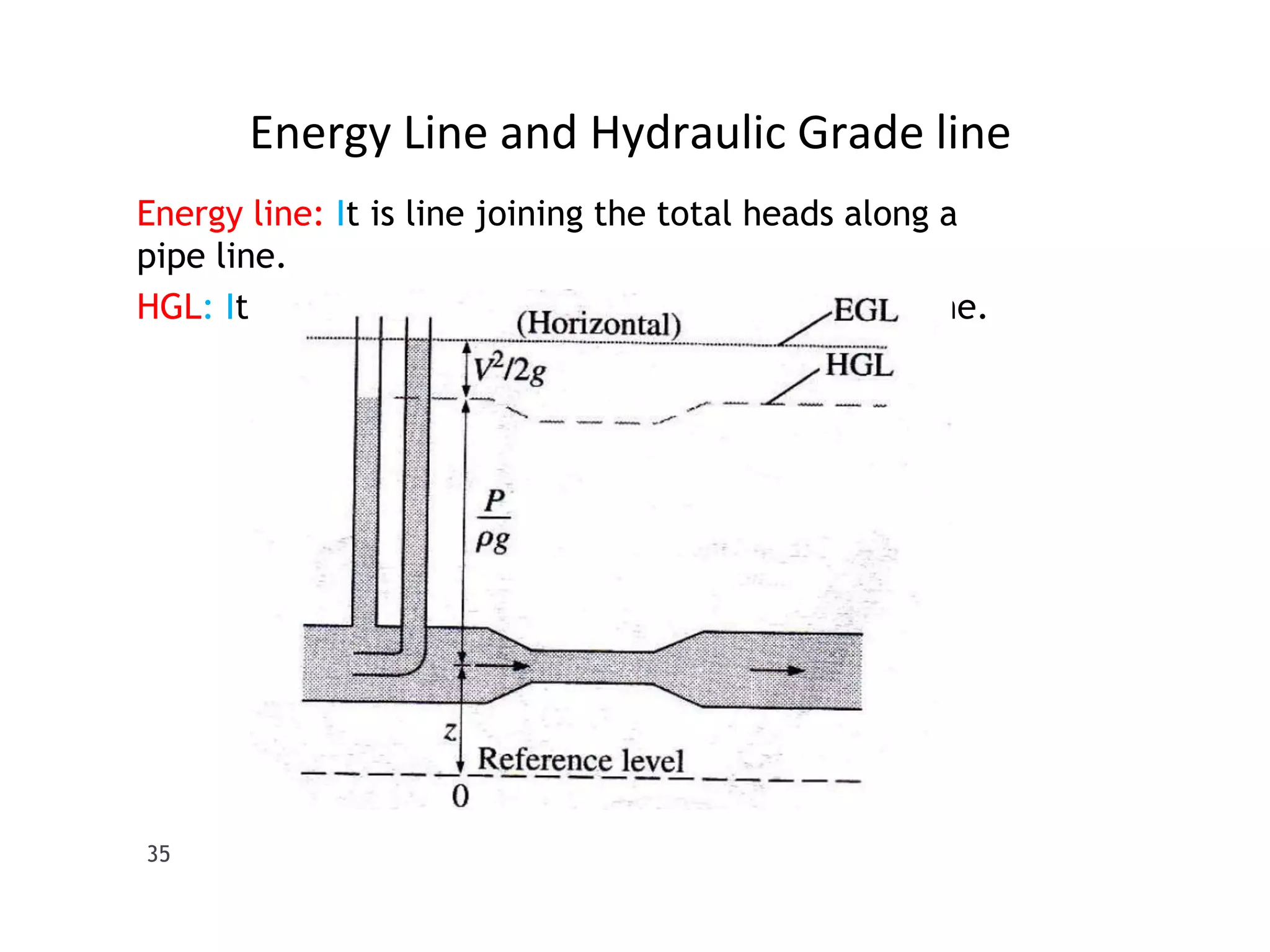
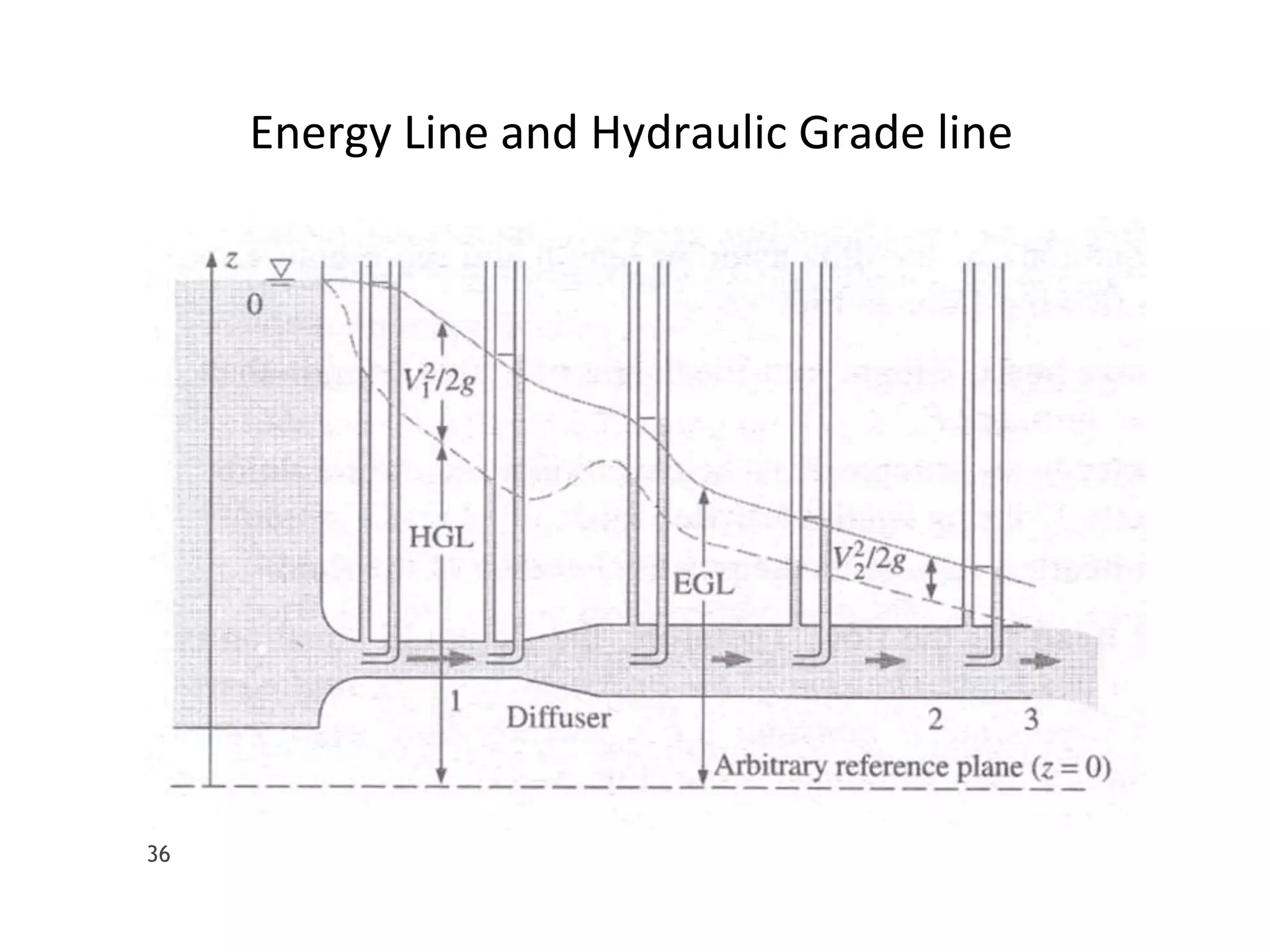
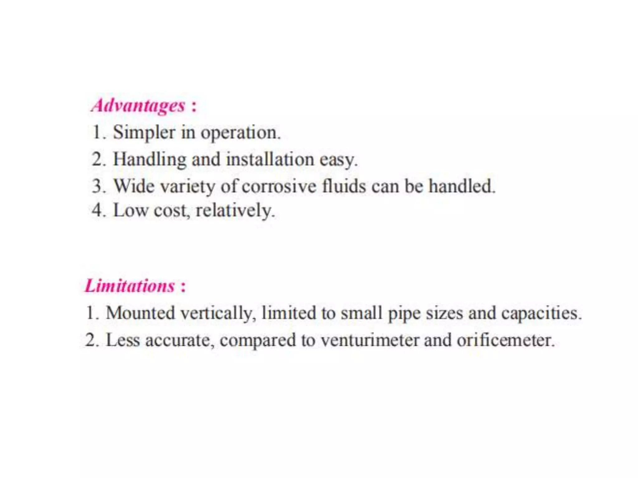
1
Fluid Dynamics
BY
TIWARE V.S.
ASSISTANT PROFESSOR
BVCOE KOLHAPUR
• Unit-4: FLUID DYNAMICS
• Forces Acting on Fluid in Motion,
• Euler’s Equation along a Streamline,
• Bernaulies equations, Bernoulli's Theorem
– assumptions, Limitations and modifications.
• Bernoulli’s Applications:
– Venturimeter (Horizontal andVertical), Orificemeter, Orifices,
• Time required for Emptying the Tank,
• Concept of HGL and TEL.
• Therotical and Experimental determination of hydraulic
coefficients of orifice.
• Introduction of mouthpiece and Rotameter.
Forms of Energy
C (1). Kinetic Energy: Energy due to motion of body. A
body of mass, m, when moving with velocity, V, posses
kinetic energy,
KE = 1 mV 2
3
PE = mgZ
m and V are mass and velocity of
body
2
C (2). Potential Energy: Energy due to elevation of body
above an arbitrary datum
Z is elevation of body from arbitrary
datum
m is the mass of
body
C (3). Pressure Energy: Energy due to pressure above datum,
most usually its pressure above atmospheric
PrE = γh = pgh
Forms of Energy
4
C (4). Internal Energy: It is the energy that is associated
with the molecular, or internal state of matter; it may
be stored in many forms, including thermal, nuclear,
chemical and electrostatic.
HEAD
C Head: Energy per unit weight is
called head
C Kinetic head: Kinetic energy per
unit weight
C Potential head: Potential energy per
unit weigh
C Pressure head: Pressure energy per
unit weight
V 2
⎠
2
⎞
Weight ⎝ 2 2g
KE
⎛
1
Kinetic head = = ⎜ mV ⎟ /
mg =
QWeight = mg
Weight
PE
= (mgZ )/ mg =
Z
Potential head =
Weight γ
5
PrE
= P
Pressure head
=
FORCES ACTING ON FLUID FLOW
1. GRAVITY FORCE (Fg)
2. PRESSURE FORCE (Fp)
3. VISCOUS FORCE (Fv)
4. TURBULANCE (Ft)
5. COMPRESSIBILITY (Fc)
TOTAL HEAD
C TOTAL HEAD
= Kinetic Head + Potential Head + Pressure Head
P V
2
+
Total Head = H = Z +
γ
2g
2g
V 2
P
γ
1
3
Z
Bernoulli’s Equation
C It states that the sum of kinetic, potential and pressure
heads of a fluid particle is constant along a streamline
during steady flow when compressibility and frictional
effects are negligible.
C i.e. , For an ideal fluid,Total head of fluid particle
remains constant during a steady-incompressible
flow.
C Or total head along a streamline is constant during
steady flow when compressibility and frictional effects
are negligible.
2
2
1
1
V 2
2
P
V 2
P
Z
V 2
+
+ =
Z +
= constt
Total Head = Z +
γ
2g
+ 1
γ
2g
P
γ
2g
1
2
Pip
e
Assumption of Bernoulli’s Equation
Fluid is ideal and incompressible Flow is steady
Flow is along streamline
Velocity is uniform across the section and is equal to
mean velocity
Only gravity and pressure forces are acting
LIMITATIONS OF BERNOULLIS
THEOREM
• There are following limitations of Bernoulli's theorem:
(i) In Bernoulli's theorem, the velocity of every particle of liquid across
any cross-section is considered uniform which is not correct. The
velocity of the particles is different in different layers.
(ii) The loss of energy when the liquid is in motion is not considered
while some kinetic energy is converted into heat and is lost.
(iii) The fluids must be incompressible as the elastic energy of the fluid
is not taken into account.
VENTURIMETER
TIME REQUIRED FOR EMPTYING A TANK THROUGH AN
ORIFICE AT ITS BOTTOM
• Consider a tank, of uniform cross-sectional area, containing some
liquid, and having an orifice at its bottom as shown in Fig.
dq = – A ·
dh
dq = – A · dh
(– ve sign of dh is taken because the value of h decreases when the discharge
increases).
Energy Line and Hydraulic Grade line
1
1
C Pitot tube: It measures
sum of pressure and
velocity heads i.e.,
P V 2
+
γ
2g
C Measurement of
Heads
C Piezometer: It
measures pressure
head ( P / γ ).
Energy Line and Hydraulic Grade line
Energy line: It is line joining the total heads along a
pipe line.
HGL: It is line joining pressure head along a pipe line.
35
Energy Line and Hydraulic Grade line
36
Energy Line and Hydraulic Grade line
1
0
C Static
Pressure :
C Dynamic
pressure :
+ z + =
H 2g
V
2
P
γ
P
C Hydrostatic Pressure: ρgZ
C Stagnation Pressure: Static pressure +
dynamic Pressure
ρV 2 / 2
= contt
2
P + ρgz +
ρ
Pressure head + Elevation head + Velocity head = Total Head
Multiplying with unit
weight,γ,
V 2
=
Pstag
2
V 2
P +
ρ
hydraulic co-efficients
• The hydraulic co-efficients (or orifice co-efficients) are
enumerated and discussed below :
• 1. Co-efficient of contraction, Cc
• 2. Co-efficient of velocity, Cν
• 3. Co-efficient of discharge, Cd
• 4. Co-efficient of resistance, Cr
• Co-efficient of Contraction (Cc) :
• The ratio of the area of the jet at vena-contracta to the area of the orifice is known
as
• Co-efficient of contraction. It is denoted by Cc.
Let,
ac = Area of jet at vena contracta, and
a = Area of orifice.
• The value of Cc varies slightly with the available head of the liquid, size and shape
of the orifice; in practice it varies from 0.613 to 0.69 but the average value is
taken as 0.64.
• Co-efficient of Velocity (Cv)
• The ratio of actual velocity (V) of the jet at vena-contracta to the theoretical
velocity (Vth) is known as Co-efficient of velocity. It is denoted by Cν and
mathematically, Cν is given as:
• where,
• V= Actual velocity, and
• H = Head under which the fluid flows out of the orifice
• The value of Cv varies from 0.95 to 0.99,depending upon the shape of orifice and
the head of liquid under which the flow takes place. For sharp-edged orifices the
value of Cν is taken as 0.98
• Co-efficient of Discharge (Cd):
• The ratio of actual discharge (Q) through an arifice to the theorerical
discharge,(Qth) is known as Co-efficient of discharge. It is dinoted by
Cd.
• Mathematically,
• The value of Cd varies from 0.62 to 0.65 depending upon size and the
shape of the orifice and the head of liquid under which the flow takes
place.
MOUTHPIECE
Rotameter
The End...!

Fluid Dynamics

  • 1.
  • 2.
    • Unit-4: FLUIDDYNAMICS • Forces Acting on Fluid in Motion, • Euler’s Equation along a Streamline, • Bernaulies equations, Bernoulli's Theorem – assumptions, Limitations and modifications. • Bernoulli’s Applications: – Venturimeter (Horizontal andVertical), Orificemeter, Orifices, • Time required for Emptying the Tank, • Concept of HGL and TEL. • Therotical and Experimental determination of hydraulic coefficients of orifice. • Introduction of mouthpiece and Rotameter.
  • 3.
    Forms of Energy C(1). Kinetic Energy: Energy due to motion of body. A body of mass, m, when moving with velocity, V, posses kinetic energy, KE = 1 mV 2 3 PE = mgZ m and V are mass and velocity of body 2 C (2). Potential Energy: Energy due to elevation of body above an arbitrary datum Z is elevation of body from arbitrary datum m is the mass of body C (3). Pressure Energy: Energy due to pressure above datum, most usually its pressure above atmospheric PrE = γh = pgh
  • 4.
    Forms of Energy 4 C(4). Internal Energy: It is the energy that is associated with the molecular, or internal state of matter; it may be stored in many forms, including thermal, nuclear, chemical and electrostatic.
  • 5.
    HEAD C Head: Energyper unit weight is called head C Kinetic head: Kinetic energy per unit weight C Potential head: Potential energy per unit weigh C Pressure head: Pressure energy per unit weight V 2 ⎠ 2 ⎞ Weight ⎝ 2 2g KE ⎛ 1 Kinetic head = = ⎜ mV ⎟ / mg = QWeight = mg Weight PE = (mgZ )/ mg = Z Potential head = Weight γ 5 PrE = P Pressure head =
  • 6.
    FORCES ACTING ONFLUID FLOW 1. GRAVITY FORCE (Fg) 2. PRESSURE FORCE (Fp) 3. VISCOUS FORCE (Fv) 4. TURBULANCE (Ft) 5. COMPRESSIBILITY (Fc)
  • 13.
    TOTAL HEAD C TOTALHEAD = Kinetic Head + Potential Head + Pressure Head P V 2 + Total Head = H = Z + γ 2g 2g V 2 P γ 1 3 Z
  • 14.
    Bernoulli’s Equation C Itstates that the sum of kinetic, potential and pressure heads of a fluid particle is constant along a streamline during steady flow when compressibility and frictional effects are negligible. C i.e. , For an ideal fluid,Total head of fluid particle remains constant during a steady-incompressible flow. C Or total head along a streamline is constant during steady flow when compressibility and frictional effects are negligible. 2 2 1 1 V 2 2 P V 2 P Z V 2 + + = Z + = constt Total Head = Z + γ 2g + 1 γ 2g P γ 2g 1 2 Pip e
  • 15.
    Assumption of Bernoulli’sEquation Fluid is ideal and incompressible Flow is steady Flow is along streamline Velocity is uniform across the section and is equal to mean velocity Only gravity and pressure forces are acting
  • 16.
    LIMITATIONS OF BERNOULLIS THEOREM •There are following limitations of Bernoulli's theorem: (i) In Bernoulli's theorem, the velocity of every particle of liquid across any cross-section is considered uniform which is not correct. The velocity of the particles is different in different layers. (ii) The loss of energy when the liquid is in motion is not considered while some kinetic energy is converted into heat and is lost. (iii) The fluids must be incompressible as the elastic energy of the fluid is not taken into account.
  • 20.
  • 31.
    TIME REQUIRED FOREMPTYING A TANK THROUGH AN ORIFICE AT ITS BOTTOM • Consider a tank, of uniform cross-sectional area, containing some liquid, and having an orifice at its bottom as shown in Fig. dq = – A · dh
  • 32.
    dq = –A · dh (– ve sign of dh is taken because the value of h decreases when the discharge increases).
  • 34.
    Energy Line andHydraulic Grade line 1 1 C Pitot tube: It measures sum of pressure and velocity heads i.e., P V 2 + γ 2g C Measurement of Heads C Piezometer: It measures pressure head ( P / γ ).
  • 35.
    Energy Line andHydraulic Grade line Energy line: It is line joining the total heads along a pipe line. HGL: It is line joining pressure head along a pipe line. 35
  • 36.
    Energy Line andHydraulic Grade line 36
  • 37.
    Energy Line andHydraulic Grade line 1 0 C Static Pressure : C Dynamic pressure : + z + = H 2g V 2 P γ P C Hydrostatic Pressure: ρgZ C Stagnation Pressure: Static pressure + dynamic Pressure ρV 2 / 2 = contt 2 P + ρgz + ρ Pressure head + Elevation head + Velocity head = Total Head Multiplying with unit weight,γ, V 2 = Pstag 2 V 2 P + ρ
  • 38.
    hydraulic co-efficients • Thehydraulic co-efficients (or orifice co-efficients) are enumerated and discussed below : • 1. Co-efficient of contraction, Cc • 2. Co-efficient of velocity, Cν • 3. Co-efficient of discharge, Cd • 4. Co-efficient of resistance, Cr
  • 39.
    • Co-efficient ofContraction (Cc) : • The ratio of the area of the jet at vena-contracta to the area of the orifice is known as • Co-efficient of contraction. It is denoted by Cc. Let, ac = Area of jet at vena contracta, and a = Area of orifice. • The value of Cc varies slightly with the available head of the liquid, size and shape of the orifice; in practice it varies from 0.613 to 0.69 but the average value is taken as 0.64.
  • 40.
    • Co-efficient ofVelocity (Cv) • The ratio of actual velocity (V) of the jet at vena-contracta to the theoretical velocity (Vth) is known as Co-efficient of velocity. It is denoted by Cν and mathematically, Cν is given as: • where, • V= Actual velocity, and • H = Head under which the fluid flows out of the orifice • The value of Cv varies from 0.95 to 0.99,depending upon the shape of orifice and the head of liquid under which the flow takes place. For sharp-edged orifices the value of Cν is taken as 0.98
  • 41.
    • Co-efficient ofDischarge (Cd): • The ratio of actual discharge (Q) through an arifice to the theorerical discharge,(Qth) is known as Co-efficient of discharge. It is dinoted by Cd. • Mathematically, • The value of Cd varies from 0.62 to 0.65 depending upon size and the shape of the orifice and the head of liquid under which the flow takes place.
  • 43.
  • 45.
  • 49.