This document provides procedures for five different material testing methods:
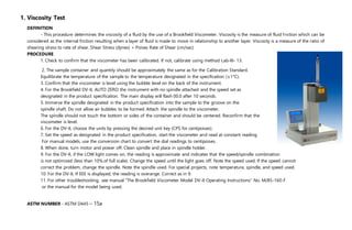
1. Viscosity testing using a Brookfield viscometer to determine the viscosity and flow properties of fluids.
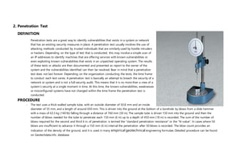
2. Penetration testing to identify vulnerabilities in systems by simulating hacking attacks.
3. A thin film oven test to evaluate how asphalt properties change during hot mixing.
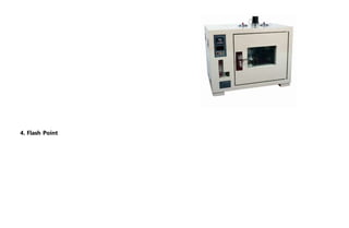
4. Measuring the flash point temperature at which vapors from a volatile material will ignite.
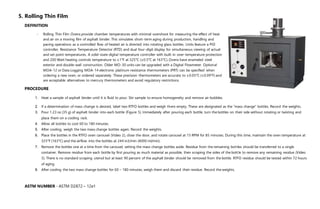
5. Rolling thin film oven testing to simulate the short-term aging effects of heat and air on moving asphalt binder films.
![ASTM NUMBER - ASTM D1586 - 11
3.Thin Film Oven Test
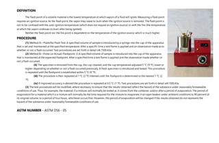
DEFINITION
This method indicates approximate change in properties of asphalt during conventional hot-mixing at about 150°C [302°F] as indicated by viscosity,
penetration, or ductility measurements. It yields a residue which approximates the asphalt condition as incorporated in the pavement. If the mixing
temperature differs appreciably from the 150°C [302°F] level, more or less effect on properties will occur.
ASTM NUMBER - ASTM D1754 / D1754M - 09](https://image.slidesharecdn.com/constructionassignment-160513160009/85/Construction-assignment-3-320.jpg)