Downloaded 196 times
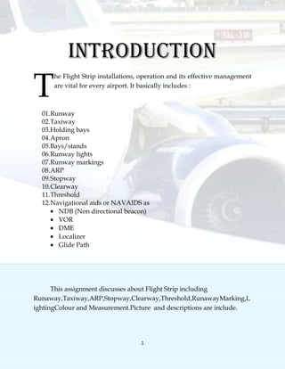
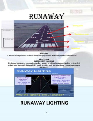
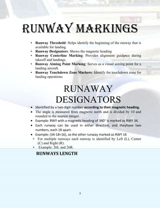
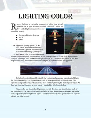
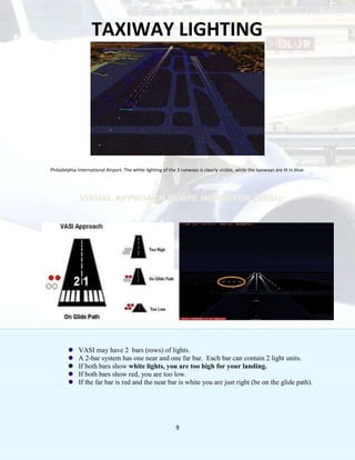
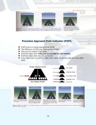
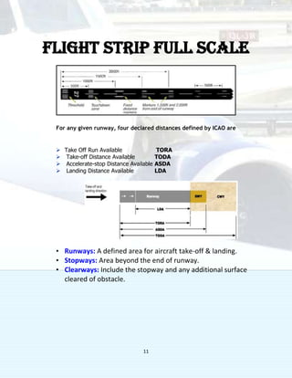
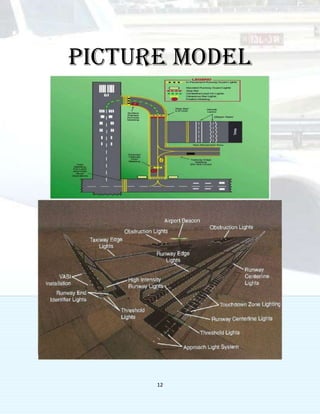
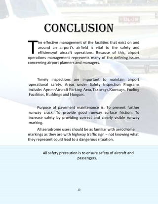

This document discusses various aspects of airport flight strips, including runways, taxiways, markings, and lighting. It describes runways as the defined areas for aircraft takeoff and landing, and taxiways as the smaller paths that allow safe surface movement. It outlines the key markings like thresholds, centerlines, and designators used on runways and taxiways. It also explains the different lighting systems like approach lighting, VASI, and PAPI that aid pilots during low visibility, and specifies the colors used to identify features. Finally, it notes the importance of effective management and maintenance of these facilities to ensure safety and efficiency of aircraft operations.


