Downloaded 200 times
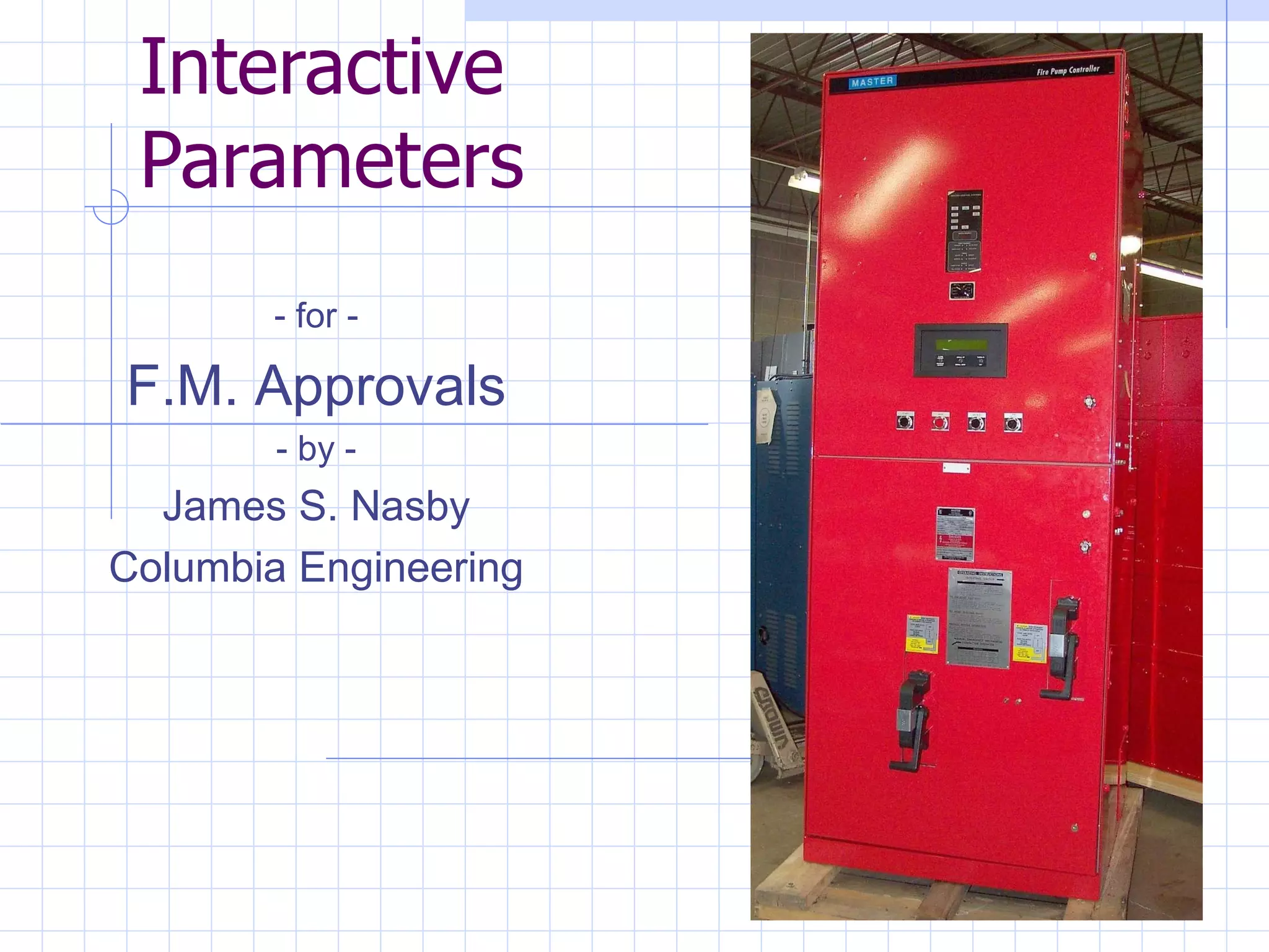
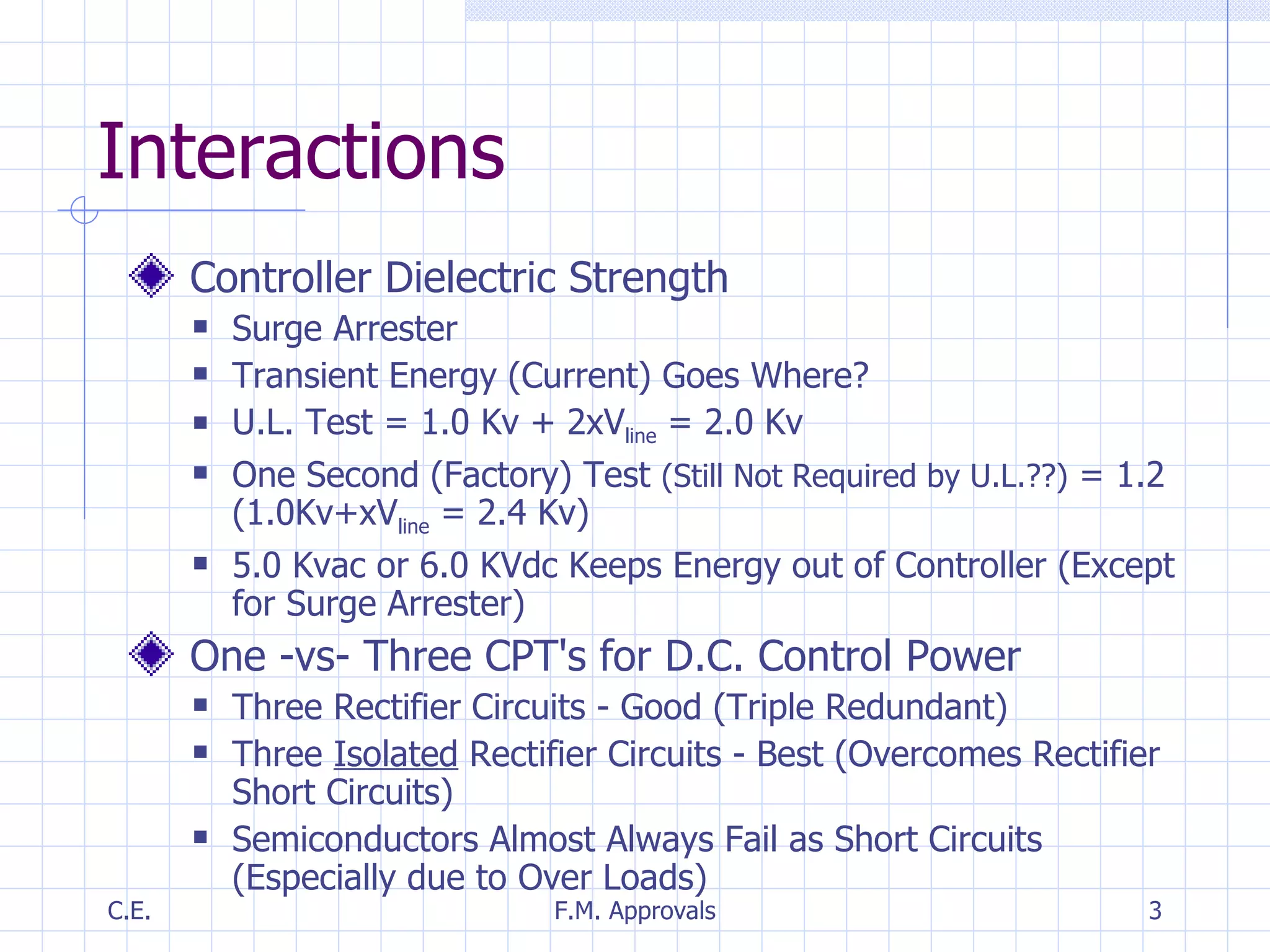
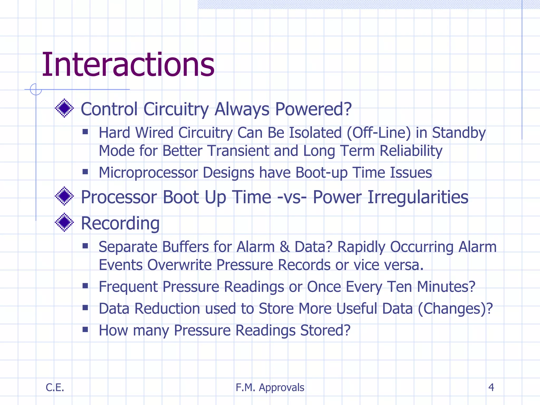
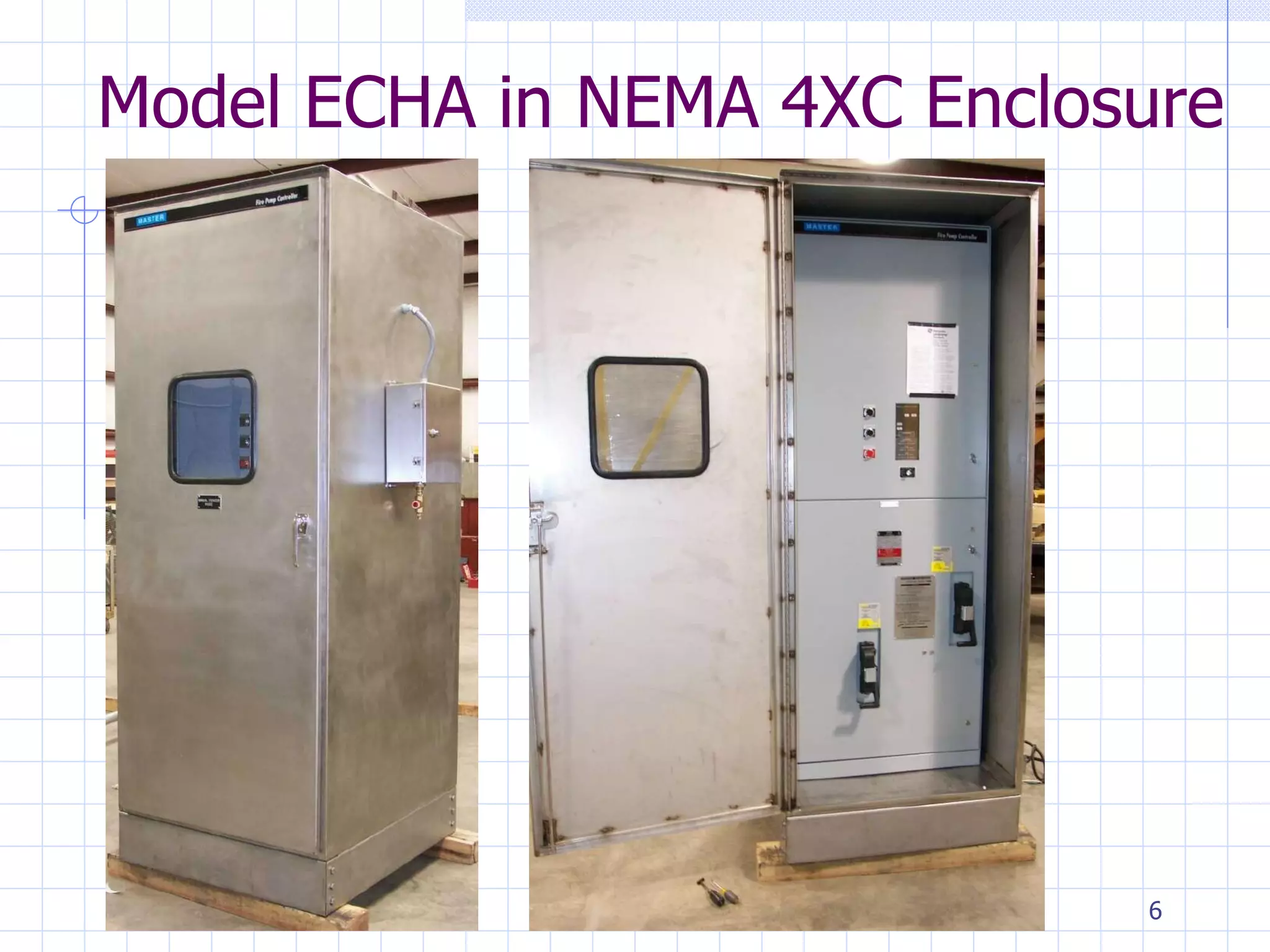
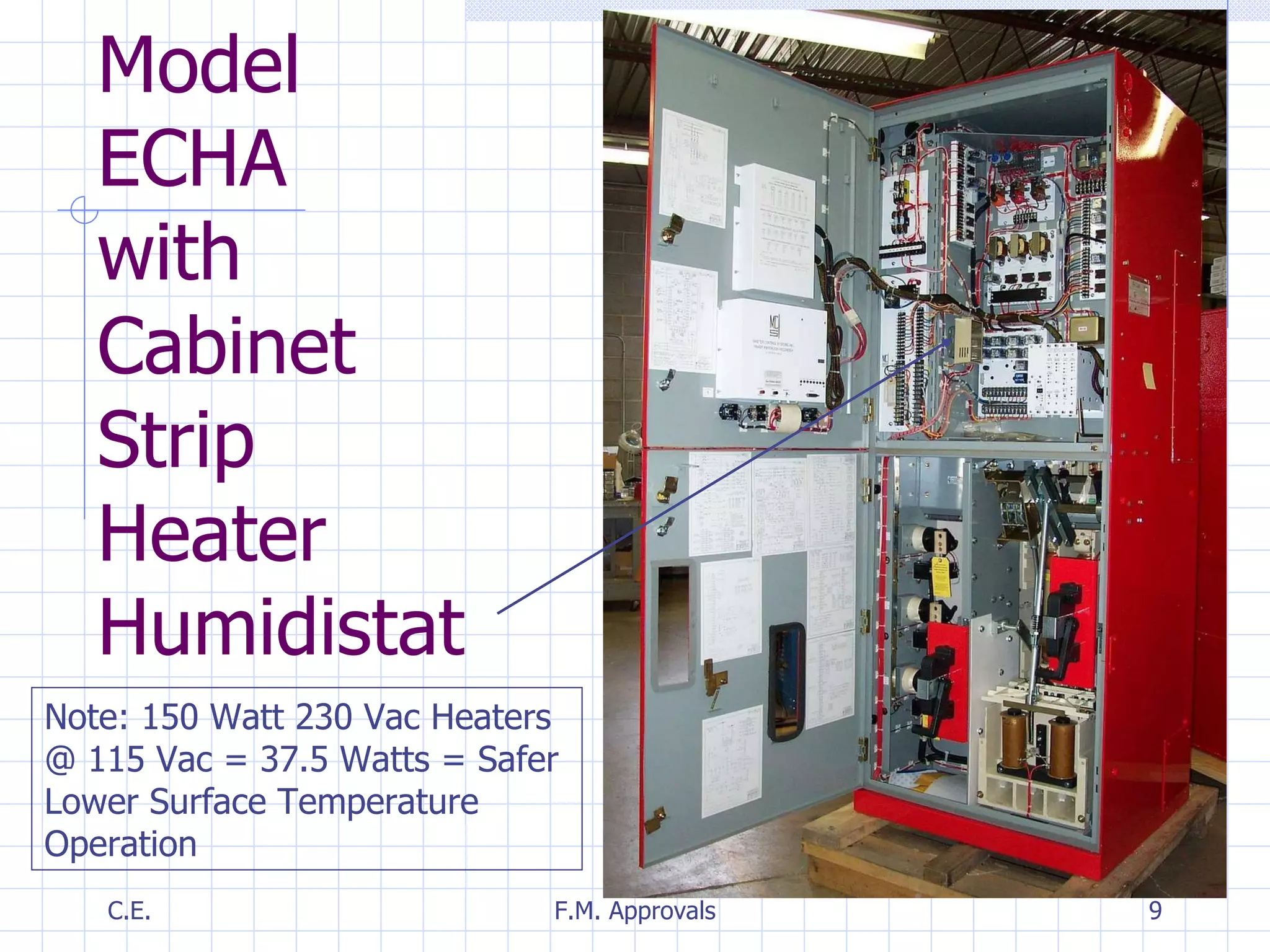
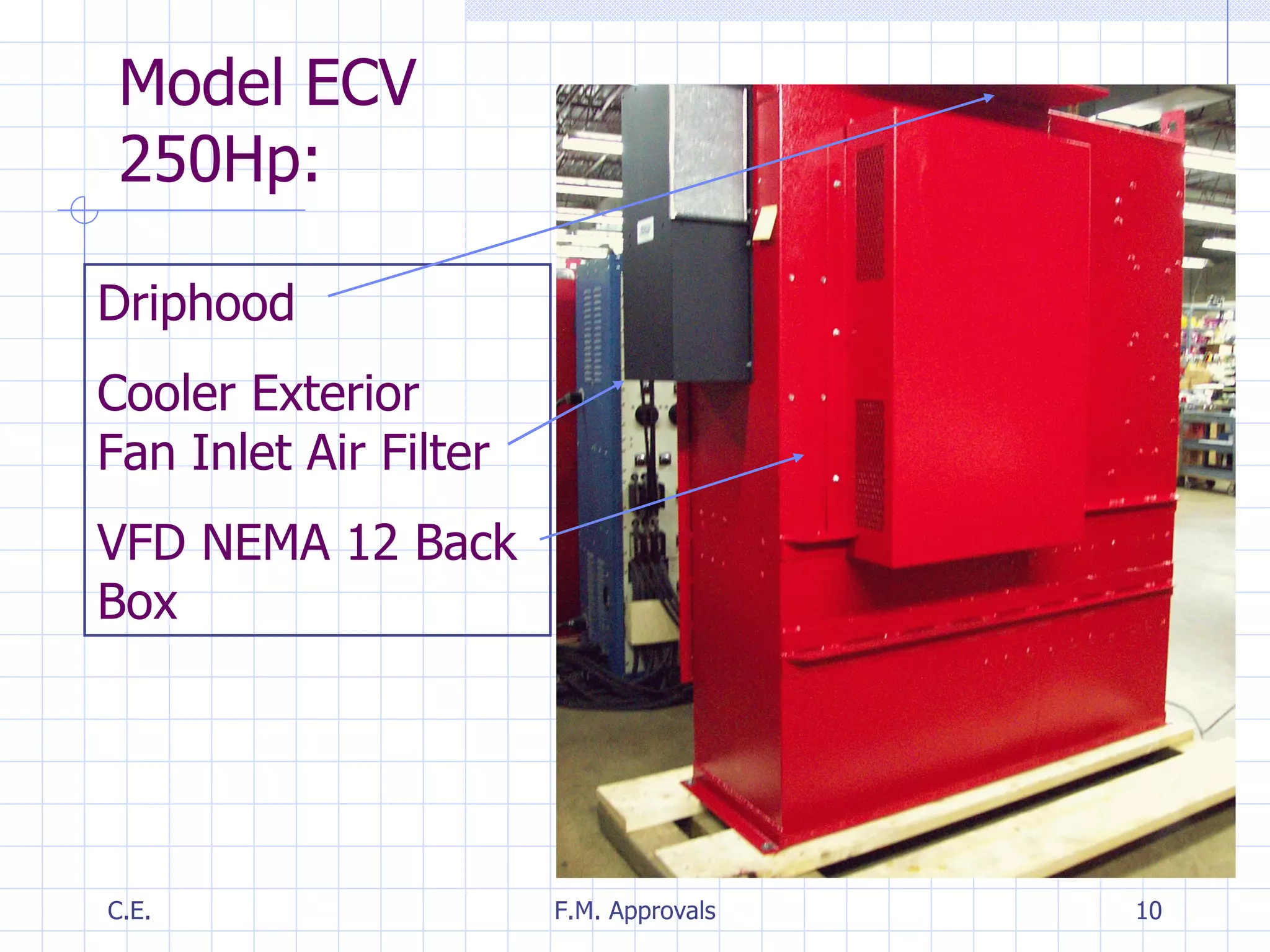
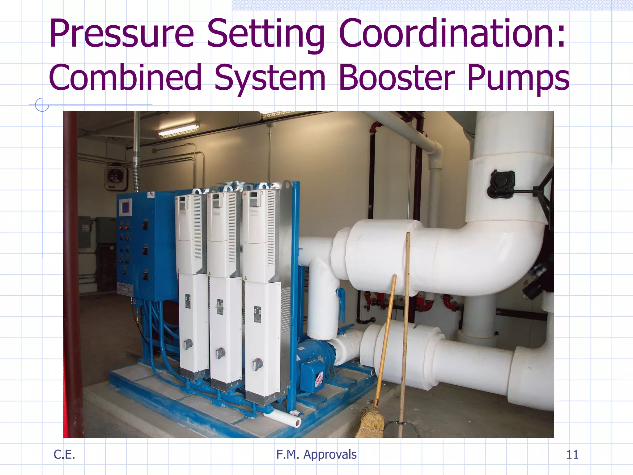
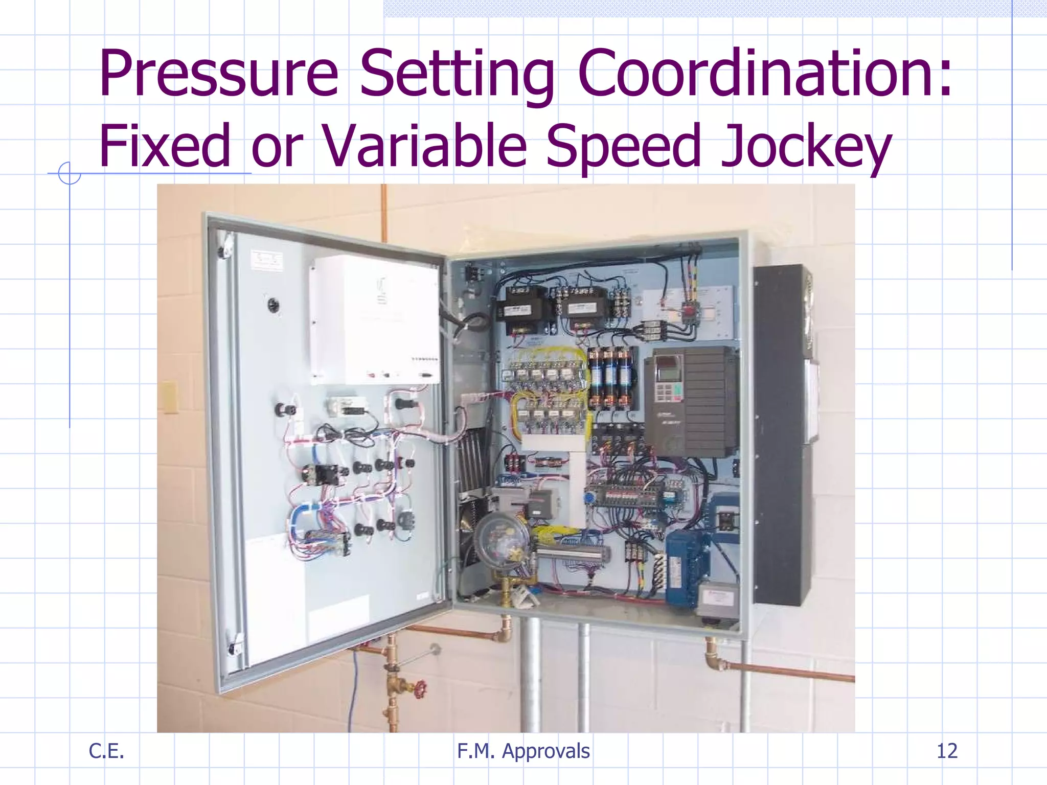
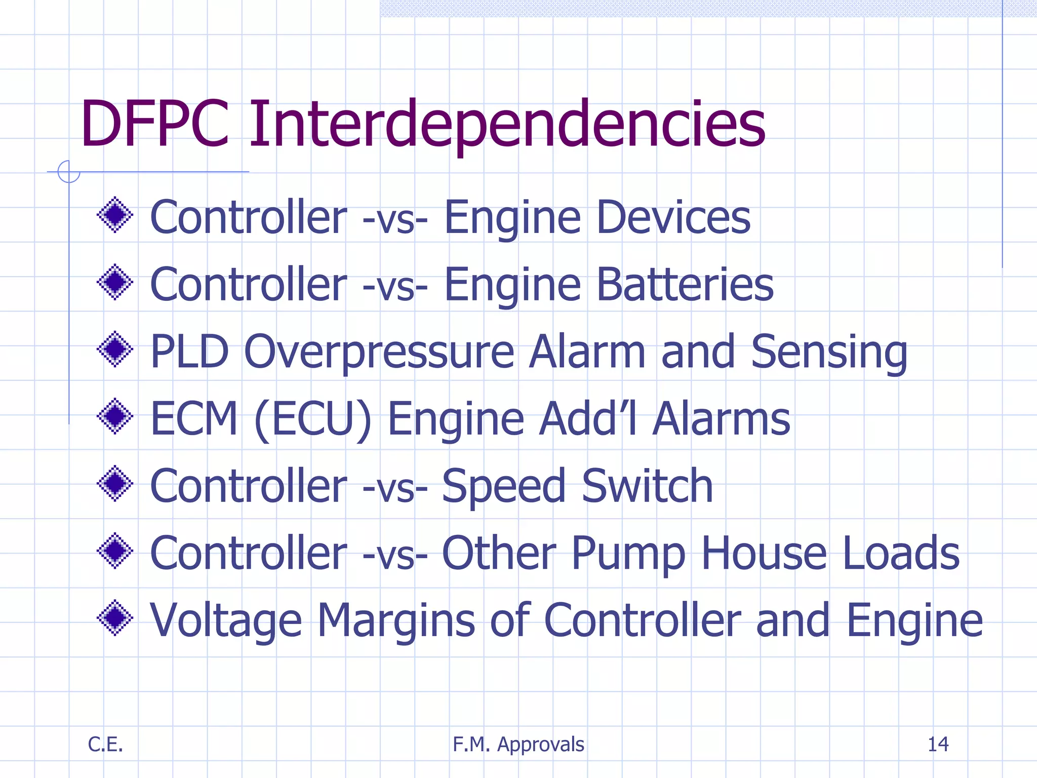
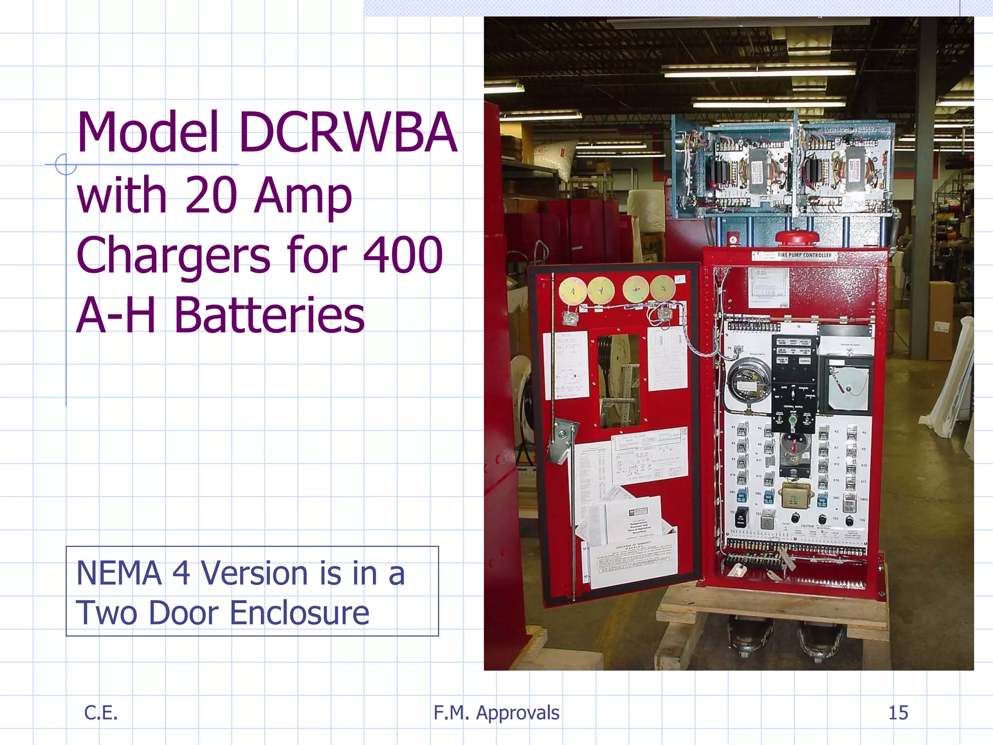
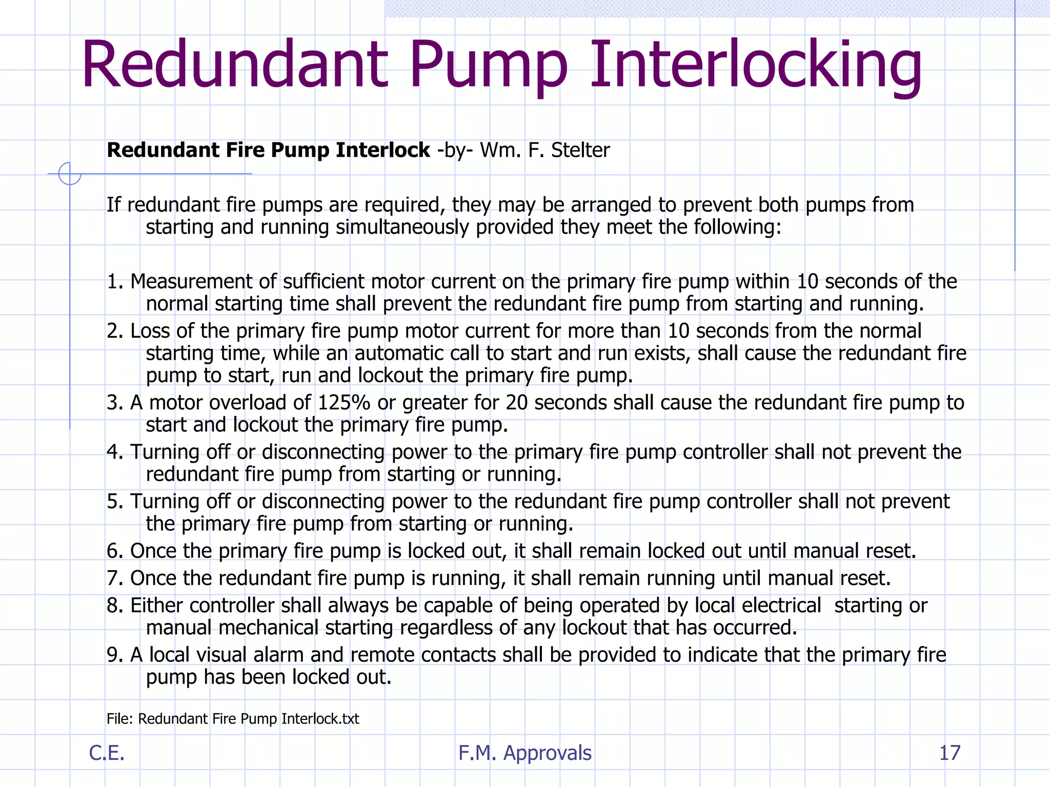
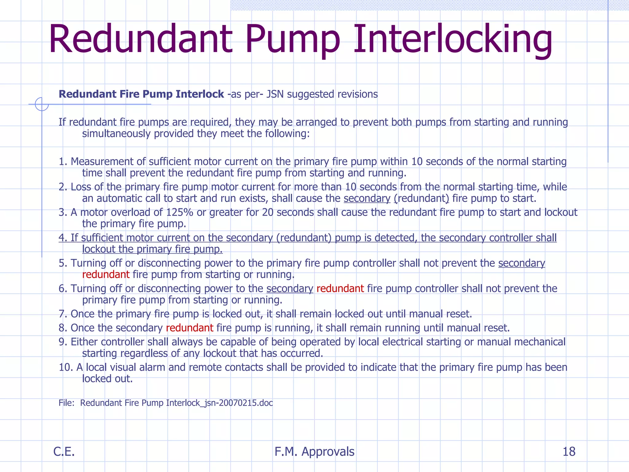

The document discusses various interactive parameters and interdependencies related to fire pump controllers. It covers topics like transient energy handling, control circuitry reliability, data recording considerations, enclosure types, single phase protection, environmental conditions, pressure coordination, and redundant pump interlocking. Redundant pump operation is addressed, noting the conditions under which the secondary pump would start and lockout the primary.


