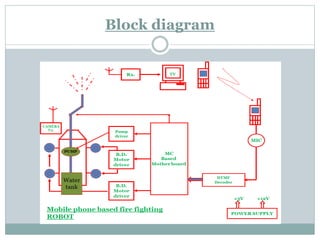
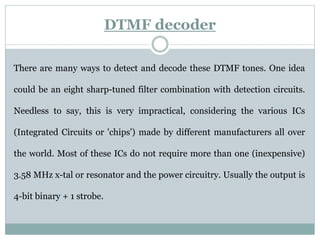
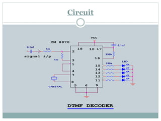
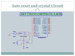
Solar based video controlled wireless
fire fighting robot
Introduction
The project aims at designing an intelligent fire extinguishing robotic vehicle which can be
controlled wirelessly through gsm communication. The Robotic vehicle has a camera
mounted on it whose direction can also be controlled using wirelessly. The proposed vehicle
has a water jet spray which is capable of sprinkling water. The sprinkler can be moved
towards the required direction. To perform this intelligent task, Microcontroller is loaded
with a program written in embedded ‘assembly’ language. And this is works on solar energy.
Contents
ABSTRACT
DESIGN PRINCIPLE
CIRCUIT DESCRIPTION
DTMF encoder and decoder
Mother board
Bidirectional motor driver
PMDC motor
Video transmitter and receiver
FUTURE EXPANSION
CONCLUSION
Design principle
When the user fed the commands to the hand held mobile phone by pressing
keys, the microcontroller interfaced to it reads the command and sends relevant
data of that command wirelessly using gsm communication to the second mobile
using DTMF principle. This data is received by the ear phone from the second
mobile on the robotic vehicle and feds it to microcontroller which acts accordingly
on motors, pump and lamp. The vehicle is mounted with a camera which helps in
viewing the live images on TV. Also, the vehicle is capable of detecting obstacles
and alerts the user through buzzer. To perform this intelligent task,
Microcontroller is loaded with a program written in embedded ‘assembly’
language. And this is works on solar energy.
GSM communication
GSM (Global System for Mobile Communications, originally Groupe Spécial
Mobile), is a standard developed by the European Telecommunications Standards
Institute (ETSI) to describe protocols for second-generation (2G) digital cellular
networks used by mobile phones. As of 2014 it has become the default global standard
for mobile communications - with over 90% market share, operating in over 219
countries and territories. GSM networks operate in a number of different carrier
frequency ranges (separated into GSM frequency ranges for 2G and UMTS frequency
bands for 3G), with most 2G GSM networks operating in the 900 MHz or 1800 MHz
bands.
Robot
 The word "robot" originates from the word for forced labor, basically a robots
consists of:
 A mechanical device, such as a wheeled platform, arm, or other construction,
capable of interacting with its environment
 Sensors on or around the device that are able to sense the environment and
give useful feedback to the device
 Systems that process sensory input in the context of the device's current
situation and instruct the device to perform actions in response to the situation
Solar energy
Solar cars depend on PV cells to convert sunlight into electricity. Unlike solar
thermal energy which converts solar energy to heat for either household
purposes, industrial purposes or to be converted to electricity, PV cells directly
convert sunlight into electricity. When sunlight (photons) strike PV cells, they
excite electrons and allow them to flow, creating an electrical current. PV cells
are made of semiconductor materials such as silicon and alloys of indium,
gallium and nitrogen. Silicon is the most common material used and has an
efficiency rate of 15-20%. That power will stored in a battery.
What is DTMF
Dual-tone multi-frequency signaling (DTMF) is an in-
band telecommunication signaling system using the voice-frequency band over
telephone lines between telephone equipment and other communications devices
and switching centers. DTMF was first developed in the Bell System in the United
States, and became known under the trademark Touch-Tone for use in push-
button telephones supplied to telephone customers, starting in 1963. DTMF is
standardized by ITU-T Recommendation Q.23. It is also known in the UK as MF4.
The Touch-Tone system using a telephone keypad gradually replaced the use
of rotary dial and has become the industry standard for landline and mobile
service. Other multi-frequency systems are used for internal signaling within the
telephone network.
Embedded system
Use of embedded processors in passenger cars, mobile phones, medical equipment,
aerospace systems and defense systems is widespread, and even everyday domestic
appliances such as dish washers, televisions, washing machines and video recorders
now include at least one such device. Because most embedded projects have severe cost
constraints, they tend to use low-cost processors like the 8051 family of devices
considered in this book. These popular chips have very limited resources available
most such devices have around 256 bytes (not megabytes!) of RAM, and the available
processor power is around 1000 times less than that of a desktop processor. As a
result, developing embedded software presents significant new challenges, even for
experienced desktop programmers. If you have some programming experience - in C,
C++ or Java - then this book and its accompanying CD will help make your move to the
embedded world as quick and painless as possible.
Block diagram
Circuit description
Solar cell
A solar cell (also called a photovoltaic cell) is an electrical device that
converts the energy of light directly into electricity by the photovoltaic effect. It
is a form of photoelectric cell (in that its electrical characteristics-- e.g.
current, voltage, or resistance-- vary when light is incident upon it) which, when
exposed to light, can generate and support an electric current without being
attached to any external voltage source. The term "photovoltaic" comes from
the Greek φῶς (phōs) meaning "light", and from "Volt", the unit of electro-
motive force, the volt, which in turn comes from the last name of
the Italian physicist Alessandro Volta, inventor of the battery (electrochemical
cell). The term "photo-voltaic" has been in use in English since 1849.
Circuit
DTMF decoder
There are many ways to detect and decode these DTMF tones. One idea
could be an eight sharp-tuned filter combination with detection circuits.
Needless to say, this is very impractical, considering the various ICs
(Integrated Circuits or 'chips') made by different manufacturers all over
the world. Most of these ICs do not require more than one (inexpensive)
3.58 MHz x-tal or resonator and the power circuitry. Usually the output is
4-bit binary + 1 strobe.
Circuit
1m
15
DTMF DECODER
LED
1
14
0.1uf
0.1uf
18
95
2
17
11
CM 8870
4
12
330e
8
signal i/p
6
7
16
3
CRYSTAL
VCC
101m
13
330k
Mother board
The motherboard of this project is designed with a MSC –51 core
compatible micro controller. The motherboard is designed on a
printed circuit board, compatible for the micro controller. This board
is consisting of a socket for micro controller, input /output pull-up
registers; oscillator section and auto reset circuit.
Auto reset and crystal Circuit
RST
10uF
22pF
22pF
8.2k
4 - 12Mhz
VCC=+5vdc
AT89C51
9
18
19
29
30
31
1
2
3
4
5
6
7
8
21
22
23
24
25
26
27
28
10
11
12
13
14
15
16
17
39
38
37
36
35
34
33
32
RST
XTAL2
XTAL1
PSEN
ALE/PROG
EA/VPP
P1.0
P1.1
P1.2
P1.3
P1.4
P1.5
P1.6
P1.7
P2.0/A8
P2.1/A9
P2.2/A10
P2.3/A11
P2.4/A12
P2.5/A13
P2.6/A14
P2.7/A15
P3.0/RXD
P3.1/TXD
P3.2/IN T0
P3.3/IN T1
P3.4/T0
P3.5/T1
P3.6/WR
P3.7/RD
P0.0/AD0
P0.1/AD1
P0.2/AD2
P0.3/AD3
P0.4/AD4
P0.5/AD5
P0.6/AD6
P0.7/AD7
MICROCONTROLLER
The auto reset circuit is a RC network as shown in the mother board
circuit diagram. A capacitor of 1-10mfd is connected in series with a 8k2
resister the R-C junction is connected to the micro controller pin –9
which is reset pin. The reset pin is one when ever kept high (logic 1) the
programme counter (PC) content resets to 0000h so the processor starts
executing the programme. From that location. When ever the system is
switched ON the mother board gets power and the capacitor acts as short
circuit and the entire voltage appears across the resistor, so the reset pin
get a logic 1 and the system get reset, whenever it is being switched ON.
Auto reset circuit
Crystal oscillator
The 8051 family microcontroller contains an inbuilt crystal oscillator, but
the crystal has to be connected externally. This family of microcontroller
can support 0 to 24MHz crystal and two numbers of decoupling
capacitors are connected as shown in the figure. These capacitors are
decouples the charges developed on the crystal surface due to
piezoelectric effect. These decoupling capacitors are normally between
20pf to 30pf. The clock generator section is designed as above,
Pull-up resistors
The PORT0 and PORT2 of the MCS-51 architecture is of
open collector type so on writing logic 0 the pins are
providing a perfect ground potential. Where as on writing
logic 1 the port pins behaves as high impedance condition
so putting a pull-up resister enables the port to provide a
+5volt (logic 1). Port1 and Port3 are provided with
internal pull-ups. A pull-up resister is normally a 10K
resistance connected from the port pin to the Vcc (+5) volt.
Circuit
AT89C51
9
18
19
29
30
31
1
2
3
4
5
6
7
8
21
22
23
24
25
26
27
28
10
11
12
13
14
15
16
17
39
38
37
36
35
34
33
32
RST
XTAL2
XTAL1
PSEN
ALE/PROG
EA/VPP
P1.0
P1.1
P1.2
P1.3
P1.4
P1.5
P1.6
P1.7
P2.0/A8
P2.1/A9
P2.2/A10
P2.3/A11
P2.4/A12
P2.5/A13
P2.6/A14
P2.7/A15
P3.0/RXD
P3.1/TXD
P3.2/INT0
P3.3/INT1
P3.4/T0
P3.5/T1
P3.6/WR
P3.7/RD
P0.0/AD0
P0.1/AD1
P0.2/AD2
P0.3/AD3
P0.4/AD4
P0.5/AD5
P0.6/AD6
P0.7/AD7
10k
PORT-0
VCC=+5V
Bi-directional motor driver
Here we drive the PMDC motor in both the direction using transistor h-
bridge of ICs l293d . An H-bridge is an arrangement of transistors that
allows a circuit full control over a standard electric DC motor. That is, with
an H-bridge a microcontroller, logic chip, or remote control can
electronically command the motor to go forward, reverse, brake, and coast.
Circuit
5
6
16
9
L 293D
11
14
4
Bi-directional motor driver
M
12
15
Vcc
M
1
3
7 D
VCC
8
A
13
B 10
C2
Motor driver
The D.C. Motor used in this project operates at 12 volt and approximately
400mA of current. The motor driver is designed to inter face the motor with
micro controller. The micro controller output is +5volt and can maximum give a
current of 5mA. The driver stage changes the current and voltage level suitably
to drive the motor. The driver stage not only drives the motor but also helps to
control the direction of rotation. As the output current (Ic) is large the driver
section requires a Darlington pair to switch the load. The Darlington pair I.C.
TIP 122 is used here for designing. There are four ICs used here but two of
those switched for one direction and other two will be switched for opposite
direction rotation of the D.C. motor. The design principle of the driver section is
as follows.
Circuit
Wireless CCTV
SPECIFICATIONS:
RF:
• Input Frequency: 430 MHz-801 MHz, Off air channels
14-69, CATV channels 54 – 65 (403 MH-469 MHz).
• Input Level: -10 to +35dBmV
• Noise Figure: UHF: 10dB
• Image Rejection: UHF: 50dB
• Input Impedance: 50 Ohms.
AUDIO:
• Output Level: 300 mV rms nominal
• Output Impedance: Less than 500 Ohms, unbalanced.
VIDEO:
• Output Level: 1.0Vp-p, NTSC standard negative sync.
• Output Impedance: 75 Ohms.
• Differential Gain: Less than 5%.
• Differential Phase: Less than 5 degrees
• L/C Delay: ±50nSec maximum
GENERAL:
• DC Power Input: +9 V - 12 VDC @ 140 mA,
• Temperature: 0° C to +50° C.
• Dimensions: 2.7" X 0,95" X 2.9"
• Weight: 60 grams
Future expansion
 This project has a vast field for expansion. The robot is designed with latest technology of
communication and control. This project is designed with constraint of time and cost.
This project can be modified and expanded in the following fields,
 The robot can be interfaced with sensor to send back the information to the user.
 The melody generator can be replaced with multiple voice stacks. So the robot can select
the appropriate message from the stack and send to the user after performing the task.
 The robot can be programmed remotely through a mobile to carry out specific task.
 The robotic arm can be modified to have gripper and more versatile arm to carry out
more critical jobs.
 The robotic arm can be designed with a web cam to send the snap shots of the location.
Conclusion
This project is designed as a concept to control a robotic
arm over mobile instruction. The project performs
satisfactorily in the laboratory condition. The accuracy
and performance is quite accurate and the errors are
observed well below the tolerance level.
--------------- Thank you ---------------

Fire fighting robot

  • 1.
    Solar based videocontrolled wireless fire fighting robot Introduction The project aims at designing an intelligent fire extinguishing robotic vehicle which can be controlled wirelessly through gsm communication. The Robotic vehicle has a camera mounted on it whose direction can also be controlled using wirelessly. The proposed vehicle has a water jet spray which is capable of sprinkling water. The sprinkler can be moved towards the required direction. To perform this intelligent task, Microcontroller is loaded with a program written in embedded ‘assembly’ language. And this is works on solar energy.
  • 2.
    Contents ABSTRACT DESIGN PRINCIPLE CIRCUIT DESCRIPTION DTMFencoder and decoder Mother board Bidirectional motor driver PMDC motor Video transmitter and receiver FUTURE EXPANSION CONCLUSION
  • 3.
    Design principle When theuser fed the commands to the hand held mobile phone by pressing keys, the microcontroller interfaced to it reads the command and sends relevant data of that command wirelessly using gsm communication to the second mobile using DTMF principle. This data is received by the ear phone from the second mobile on the robotic vehicle and feds it to microcontroller which acts accordingly on motors, pump and lamp. The vehicle is mounted with a camera which helps in viewing the live images on TV. Also, the vehicle is capable of detecting obstacles and alerts the user through buzzer. To perform this intelligent task, Microcontroller is loaded with a program written in embedded ‘assembly’ language. And this is works on solar energy.
  • 4.
    GSM communication GSM (GlobalSystem for Mobile Communications, originally Groupe Spécial Mobile), is a standard developed by the European Telecommunications Standards Institute (ETSI) to describe protocols for second-generation (2G) digital cellular networks used by mobile phones. As of 2014 it has become the default global standard for mobile communications - with over 90% market share, operating in over 219 countries and territories. GSM networks operate in a number of different carrier frequency ranges (separated into GSM frequency ranges for 2G and UMTS frequency bands for 3G), with most 2G GSM networks operating in the 900 MHz or 1800 MHz bands.
  • 5.
    Robot  The word"robot" originates from the word for forced labor, basically a robots consists of:  A mechanical device, such as a wheeled platform, arm, or other construction, capable of interacting with its environment  Sensors on or around the device that are able to sense the environment and give useful feedback to the device  Systems that process sensory input in the context of the device's current situation and instruct the device to perform actions in response to the situation
  • 6.
    Solar energy Solar carsdepend on PV cells to convert sunlight into electricity. Unlike solar thermal energy which converts solar energy to heat for either household purposes, industrial purposes or to be converted to electricity, PV cells directly convert sunlight into electricity. When sunlight (photons) strike PV cells, they excite electrons and allow them to flow, creating an electrical current. PV cells are made of semiconductor materials such as silicon and alloys of indium, gallium and nitrogen. Silicon is the most common material used and has an efficiency rate of 15-20%. That power will stored in a battery.
  • 7.
    What is DTMF Dual-tonemulti-frequency signaling (DTMF) is an in- band telecommunication signaling system using the voice-frequency band over telephone lines between telephone equipment and other communications devices and switching centers. DTMF was first developed in the Bell System in the United States, and became known under the trademark Touch-Tone for use in push- button telephones supplied to telephone customers, starting in 1963. DTMF is standardized by ITU-T Recommendation Q.23. It is also known in the UK as MF4. The Touch-Tone system using a telephone keypad gradually replaced the use of rotary dial and has become the industry standard for landline and mobile service. Other multi-frequency systems are used for internal signaling within the telephone network.
  • 8.
    Embedded system Use ofembedded processors in passenger cars, mobile phones, medical equipment, aerospace systems and defense systems is widespread, and even everyday domestic appliances such as dish washers, televisions, washing machines and video recorders now include at least one such device. Because most embedded projects have severe cost constraints, they tend to use low-cost processors like the 8051 family of devices considered in this book. These popular chips have very limited resources available most such devices have around 256 bytes (not megabytes!) of RAM, and the available processor power is around 1000 times less than that of a desktop processor. As a result, developing embedded software presents significant new challenges, even for experienced desktop programmers. If you have some programming experience - in C, C++ or Java - then this book and its accompanying CD will help make your move to the embedded world as quick and painless as possible.
  • 9.
  • 10.
    Circuit description Solar cell Asolar cell (also called a photovoltaic cell) is an electrical device that converts the energy of light directly into electricity by the photovoltaic effect. It is a form of photoelectric cell (in that its electrical characteristics-- e.g. current, voltage, or resistance-- vary when light is incident upon it) which, when exposed to light, can generate and support an electric current without being attached to any external voltage source. The term "photovoltaic" comes from the Greek φῶς (phōs) meaning "light", and from "Volt", the unit of electro- motive force, the volt, which in turn comes from the last name of the Italian physicist Alessandro Volta, inventor of the battery (electrochemical cell). The term "photo-voltaic" has been in use in English since 1849.
  • 11.
  • 12.
    DTMF decoder There aremany ways to detect and decode these DTMF tones. One idea could be an eight sharp-tuned filter combination with detection circuits. Needless to say, this is very impractical, considering the various ICs (Integrated Circuits or 'chips') made by different manufacturers all over the world. Most of these ICs do not require more than one (inexpensive) 3.58 MHz x-tal or resonator and the power circuitry. Usually the output is 4-bit binary + 1 strobe.
  • 13.
  • 14.
    Mother board The motherboardof this project is designed with a MSC –51 core compatible micro controller. The motherboard is designed on a printed circuit board, compatible for the micro controller. This board is consisting of a socket for micro controller, input /output pull-up registers; oscillator section and auto reset circuit.
  • 15.
    Auto reset andcrystal Circuit RST 10uF 22pF 22pF 8.2k 4 - 12Mhz VCC=+5vdc AT89C51 9 18 19 29 30 31 1 2 3 4 5 6 7 8 21 22 23 24 25 26 27 28 10 11 12 13 14 15 16 17 39 38 37 36 35 34 33 32 RST XTAL2 XTAL1 PSEN ALE/PROG EA/VPP P1.0 P1.1 P1.2 P1.3 P1.4 P1.5 P1.6 P1.7 P2.0/A8 P2.1/A9 P2.2/A10 P2.3/A11 P2.4/A12 P2.5/A13 P2.6/A14 P2.7/A15 P3.0/RXD P3.1/TXD P3.2/IN T0 P3.3/IN T1 P3.4/T0 P3.5/T1 P3.6/WR P3.7/RD P0.0/AD0 P0.1/AD1 P0.2/AD2 P0.3/AD3 P0.4/AD4 P0.5/AD5 P0.6/AD6 P0.7/AD7 MICROCONTROLLER
  • 16.
    The auto resetcircuit is a RC network as shown in the mother board circuit diagram. A capacitor of 1-10mfd is connected in series with a 8k2 resister the R-C junction is connected to the micro controller pin –9 which is reset pin. The reset pin is one when ever kept high (logic 1) the programme counter (PC) content resets to 0000h so the processor starts executing the programme. From that location. When ever the system is switched ON the mother board gets power and the capacitor acts as short circuit and the entire voltage appears across the resistor, so the reset pin get a logic 1 and the system get reset, whenever it is being switched ON. Auto reset circuit
  • 17.
    Crystal oscillator The 8051family microcontroller contains an inbuilt crystal oscillator, but the crystal has to be connected externally. This family of microcontroller can support 0 to 24MHz crystal and two numbers of decoupling capacitors are connected as shown in the figure. These capacitors are decouples the charges developed on the crystal surface due to piezoelectric effect. These decoupling capacitors are normally between 20pf to 30pf. The clock generator section is designed as above,
  • 18.
    Pull-up resistors The PORT0and PORT2 of the MCS-51 architecture is of open collector type so on writing logic 0 the pins are providing a perfect ground potential. Where as on writing logic 1 the port pins behaves as high impedance condition so putting a pull-up resister enables the port to provide a +5volt (logic 1). Port1 and Port3 are provided with internal pull-ups. A pull-up resister is normally a 10K resistance connected from the port pin to the Vcc (+5) volt.
  • 19.
  • 20.
    Bi-directional motor driver Herewe drive the PMDC motor in both the direction using transistor h- bridge of ICs l293d . An H-bridge is an arrangement of transistors that allows a circuit full control over a standard electric DC motor. That is, with an H-bridge a microcontroller, logic chip, or remote control can electronically command the motor to go forward, reverse, brake, and coast.
  • 21.
    Circuit 5 6 16 9 L 293D 11 14 4 Bi-directional motordriver M 12 15 Vcc M 1 3 7 D VCC 8 A 13 B 10 C2
  • 22.
    Motor driver The D.C.Motor used in this project operates at 12 volt and approximately 400mA of current. The motor driver is designed to inter face the motor with micro controller. The micro controller output is +5volt and can maximum give a current of 5mA. The driver stage changes the current and voltage level suitably to drive the motor. The driver stage not only drives the motor but also helps to control the direction of rotation. As the output current (Ic) is large the driver section requires a Darlington pair to switch the load. The Darlington pair I.C. TIP 122 is used here for designing. There are four ICs used here but two of those switched for one direction and other two will be switched for opposite direction rotation of the D.C. motor. The design principle of the driver section is as follows.
  • 23.
  • 25.
    Wireless CCTV SPECIFICATIONS: RF: • InputFrequency: 430 MHz-801 MHz, Off air channels 14-69, CATV channels 54 – 65 (403 MH-469 MHz). • Input Level: -10 to +35dBmV • Noise Figure: UHF: 10dB • Image Rejection: UHF: 50dB • Input Impedance: 50 Ohms. AUDIO: • Output Level: 300 mV rms nominal • Output Impedance: Less than 500 Ohms, unbalanced. VIDEO: • Output Level: 1.0Vp-p, NTSC standard negative sync. • Output Impedance: 75 Ohms. • Differential Gain: Less than 5%. • Differential Phase: Less than 5 degrees • L/C Delay: ±50nSec maximum GENERAL: • DC Power Input: +9 V - 12 VDC @ 140 mA, • Temperature: 0° C to +50° C. • Dimensions: 2.7" X 0,95" X 2.9" • Weight: 60 grams
  • 26.
    Future expansion  Thisproject has a vast field for expansion. The robot is designed with latest technology of communication and control. This project is designed with constraint of time and cost. This project can be modified and expanded in the following fields,  The robot can be interfaced with sensor to send back the information to the user.  The melody generator can be replaced with multiple voice stacks. So the robot can select the appropriate message from the stack and send to the user after performing the task.  The robot can be programmed remotely through a mobile to carry out specific task.  The robotic arm can be modified to have gripper and more versatile arm to carry out more critical jobs.  The robotic arm can be designed with a web cam to send the snap shots of the location.
  • 27.
    Conclusion This project isdesigned as a concept to control a robotic arm over mobile instruction. The project performs satisfactorily in the laboratory condition. The accuracy and performance is quite accurate and the errors are observed well below the tolerance level.
  • 28.