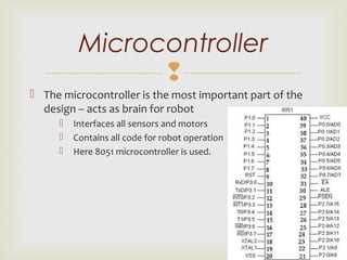
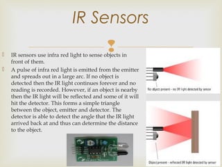
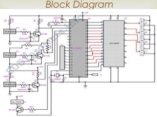
Centre for Fire, Explosive & Environment
Safety (CFEES)
DRDO, Ministry of Defence
vibs
 
VIBHANSHU SINGH
ECE, 4th
Year

 This is movement based robot. It used to sense the fire
and spreads the water over that direction.
 Firefighting is the act of extinguishing fires, i.e.; it
sprinkles water on to fire.
 The robotic vehicle is loaded with the water tanker and
a pump which is controlled by microcontroller.
Introduction

• The robotic vehicle consists of the following units:
• A rectangular base to support the whole robot
structure, attached to Four wheels for motion.
• Four DC motors to provide required movement to the
robot.
• Power is provided by 9.6 V rechargeable batteries
• Water tank is used to extinguish fire
• Consist of IR sensor and proximity Sensor.
• Consist of LM 35 sensor for temperature measurement.
Designing the Robot

 The robot vehicle loaded with the water tanker.
 The pump is controlled by an 8051 microcontroller.
 All motors are connected to the microcontroller.
 An IR sensor, Proximity sensor and LM35 are connected to
microprocessor.
 Using these sensors commands are sent to the microcontroller and
control moment of the robot like forward, backward, left, right.
 These sensors detect the fire and helps robot to extinguish fire.
 Once the robot reaches the desired location, then the robot stops
and activates the sprayer to that fire.
Working Principle

 The microcontroller is the most important part of the
design – acts as brain for robot
 Interfaces all sensors and motors
 Contains all code for robot operation
 Here 8051 microcontroller is used.
Microcontroller

 Sensors were needed to detect candle flame, exact
location of candle flame, temperature and robot’s
proximity to measure the distance from fire.
 Several sensors chosen
 IR Sensor
 LM 35 Temperature Sensor
 Proximity Sensors
Sensors

IR Sensors
 IR sensors use infra red light to sense objects in
front of them.
 A pulse of infra red light is emitted from the emitter
and spreads out in a large arc. If no object is
detected then the IR light continues forever and no
reading is recorded. However, if an object is nearby
then the IR light will be reflected and some of it will
hit the detector. This forms a simple triangle
between the object, emitter and detector. The
detector is able to detect the angle that the IR light
arrived back at and thus can determine the distance
to the object.

LM35 Temperature Sensor
 Temperature sensor is a device which senses variations in temperature across it. LM35 is
a basic temperature sensor. It give the readings in centigrade(degree Celsius)since its
output voltage is linearly proportional to temperature. It uses the fact that as
temperature increases, the voltage across diode increases at known rate(actually the
drop across base-emitter junction of transistor).
 Features
 Calibrated directly in ˚ Celsius (Centigrade)
 Rated for full l −55˚ to +150˚C range
 Suitable for remote applications
 Low cost due to wafer-level trimming
 Operates from 4 to 30 volts
 Low self-heating,
 ±1/4˚C of typical nonlinearity
 A proximity sensor is a sensor able to detect the presence 
of nearby objects without any physical contact.
 A proximity sensor often emits an electromagnetic field or a 
beam of electromagnetic radiation (infrared, for instance), 
and looks for changes in the field or return signal. The object 
being sensed is often referred to as the proximity sensor's 
target. Different proximity sensor targets demand different 
sensors. For example, a capacitive or photoelectric 
sensor might be suitable for a plastic target; an 
inductive proximity sensor always requires a metal target.
Proximity sensor

Block Diagram

 Prevention from dangerous incidents.
 
 Minimization of –ecological consequences –financial 
loss –a threat to a human life. 
 Protect fireman from risk their life.
 Provide facility to fire station to extinguish the fire.
Advantages

 Suitable for:
 Fire department 
 Factory 
 High explosion area
  chemical industries 
 Petrol station 
Applications
Experimental work has been carried out carefully.
The proposed method is verified to be great beneficial for the security
purpose and industrial purpose.
The project has been motivated by the desire to design a system that can
detect fires and take appropriate action, without any human intervention.
This provides us the opportunity to pass on to robots tasks that traditionally
humans had to do but were inherently life threatening.
It can be enhanced by interfacing it with a wireless camera so that the
person controlling it can view the operation of the robot remotely on a
screen.
Conclusions

Robotics References:
3. http://members.verizon.net/~vze2b2zf/robotpage.html
4. http://abrobotics.tripod.com/Snuffy/snuffy.htm
Part References:
5. http://bd.thrijswijk.nl/thrsim11/68hc11/about2.htm.
6. http://abrobotics.tripod.com/Snuffy/uvtron.htm
7. http://www.acroname.com
Book References:
8. Software and Hardware Engineering, Fredrick M. Cady,
Copyright 1997, Oxford University Press, Inc.
References

Fire fighting robot using 8051 microcontroller

  • 1.
      Centre for Fire,Explosive & Environment Safety (CFEES) DRDO, Ministry of Defence vibs   VIBHANSHU SINGH ECE, 4th Year
  • 2.
      This ismovement based robot. It used to sense the fire and spreads the water over that direction.  Firefighting is the act of extinguishing fires, i.e.; it sprinkles water on to fire.  The robotic vehicle is loaded with the water tanker and a pump which is controlled by microcontroller. Introduction
  • 3.
     • The roboticvehicle consists of the following units: • A rectangular base to support the whole robot structure, attached to Four wheels for motion. • Four DC motors to provide required movement to the robot. • Power is provided by 9.6 V rechargeable batteries • Water tank is used to extinguish fire • Consist of IR sensor and proximity Sensor. • Consist of LM 35 sensor for temperature measurement. Designing the Robot
  • 4.
      The robotvehicle loaded with the water tanker.  The pump is controlled by an 8051 microcontroller.  All motors are connected to the microcontroller.  An IR sensor, Proximity sensor and LM35 are connected to microprocessor.  Using these sensors commands are sent to the microcontroller and control moment of the robot like forward, backward, left, right.  These sensors detect the fire and helps robot to extinguish fire.  Once the robot reaches the desired location, then the robot stops and activates the sprayer to that fire. Working Principle
  • 5.
      The microcontrolleris the most important part of the design – acts as brain for robot  Interfaces all sensors and motors  Contains all code for robot operation  Here 8051 microcontroller is used. Microcontroller
  • 6.
      Sensors wereneeded to detect candle flame, exact location of candle flame, temperature and robot’s proximity to measure the distance from fire.  Several sensors chosen  IR Sensor  LM 35 Temperature Sensor  Proximity Sensors Sensors
  • 7.
     IR Sensors  IRsensors use infra red light to sense objects in front of them.  A pulse of infra red light is emitted from the emitter and spreads out in a large arc. If no object is detected then the IR light continues forever and no reading is recorded. However, if an object is nearby then the IR light will be reflected and some of it will hit the detector. This forms a simple triangle between the object, emitter and detector. The detector is able to detect the angle that the IR light arrived back at and thus can determine the distance to the object.
  • 8.
     LM35 Temperature Sensor Temperature sensor is a device which senses variations in temperature across it. LM35 is a basic temperature sensor. It give the readings in centigrade(degree Celsius)since its output voltage is linearly proportional to temperature. It uses the fact that as temperature increases, the voltage across diode increases at known rate(actually the drop across base-emitter junction of transistor).  Features  Calibrated directly in ˚ Celsius (Centigrade)  Rated for full l −55˚ to +150˚C range  Suitable for remote applications  Low cost due to wafer-level trimming  Operates from 4 to 30 volts  Low self-heating,  ±1/4˚C of typical nonlinearity
  • 9.
     A proximity sensor is a sensor able to detect the presence  of nearby objects without any physical contact. A proximity sensor often emits an electromagnetic field or a  beam of electromagnetic radiation (infrared, for instance),  and looks for changes in the field or return signal. The object  being sensed is often referred to as the proximity sensor's  target. Different proximity sensor targets demand different  sensors. For example, a capacitive or photoelectric  sensor might be suitable for a plastic target; an  inductive proximity sensor always requires a metal target. Proximity sensor
  • 10.
  • 11.
      Prevention from dangerous incidents.    Minimization of –ecological consequences –financial  loss –a threat to a human life.  Protect fireman from risk their life.  Provide facility to fire station to extinguish the fire. Advantages
  • 12.
      Suitable for:  Fire department  Factory   High explosion area   chemical industries   Petrol station  Applications
  • 13.
    Experimental work hasbeen carried out carefully. The proposed method is verified to be great beneficial for the security purpose and industrial purpose. The project has been motivated by the desire to design a system that can detect fires and take appropriate action, without any human intervention. This provides us the opportunity to pass on to robots tasks that traditionally humans had to do but were inherently life threatening. It can be enhanced by interfacing it with a wireless camera so that the person controlling it can view the operation of the robot remotely on a screen. Conclusions
  • 14.
     Robotics References: 3. http://members.verizon.net/~vze2b2zf/robotpage.html 4.http://abrobotics.tripod.com/Snuffy/snuffy.htm Part References: 5. http://bd.thrijswijk.nl/thrsim11/68hc11/about2.htm. 6. http://abrobotics.tripod.com/Snuffy/uvtron.htm 7. http://www.acroname.com Book References: 8. Software and Hardware Engineering, Fredrick M. Cady, Copyright 1997, Oxford University Press, Inc. References