Download to read offline

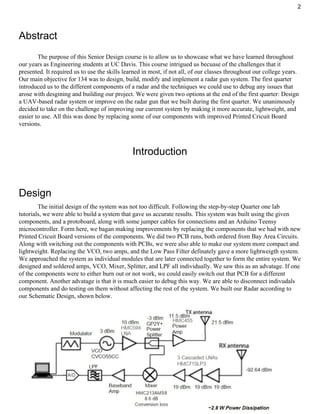


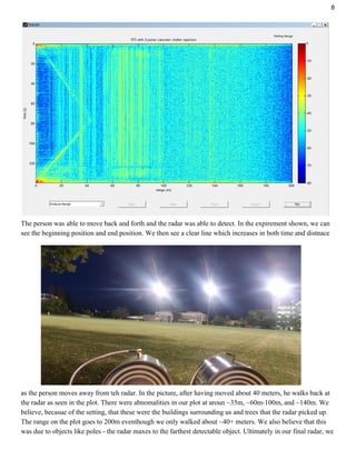

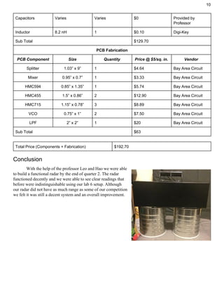

This document describes a Doppler radar system designed by a student team for a senior design course. The team aimed to improve the accuracy, weight, and usability of a radar gun system built in a previous quarter by replacing components with printed circuit board versions. The design process and testing of individual components like the low pass filter, amplifiers, voltage controlled oscillator, splitter, and mixer are discussed. The team connected the components following a schematic but initially had issues with noise and accuracy that were addressed by replacing some amplifiers. The final system showed improvement in detecting motion over 20 meters but still had room for enhanced performance.