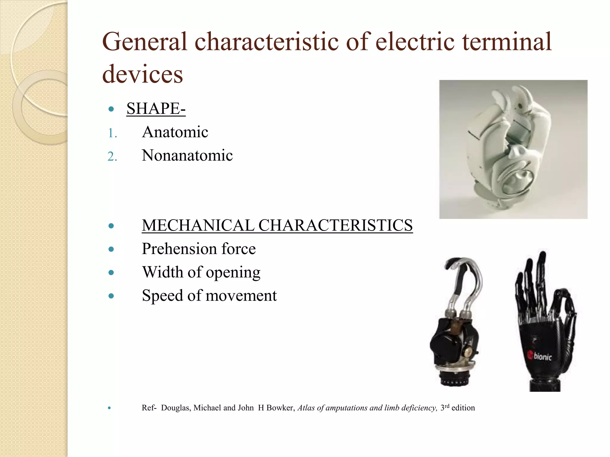
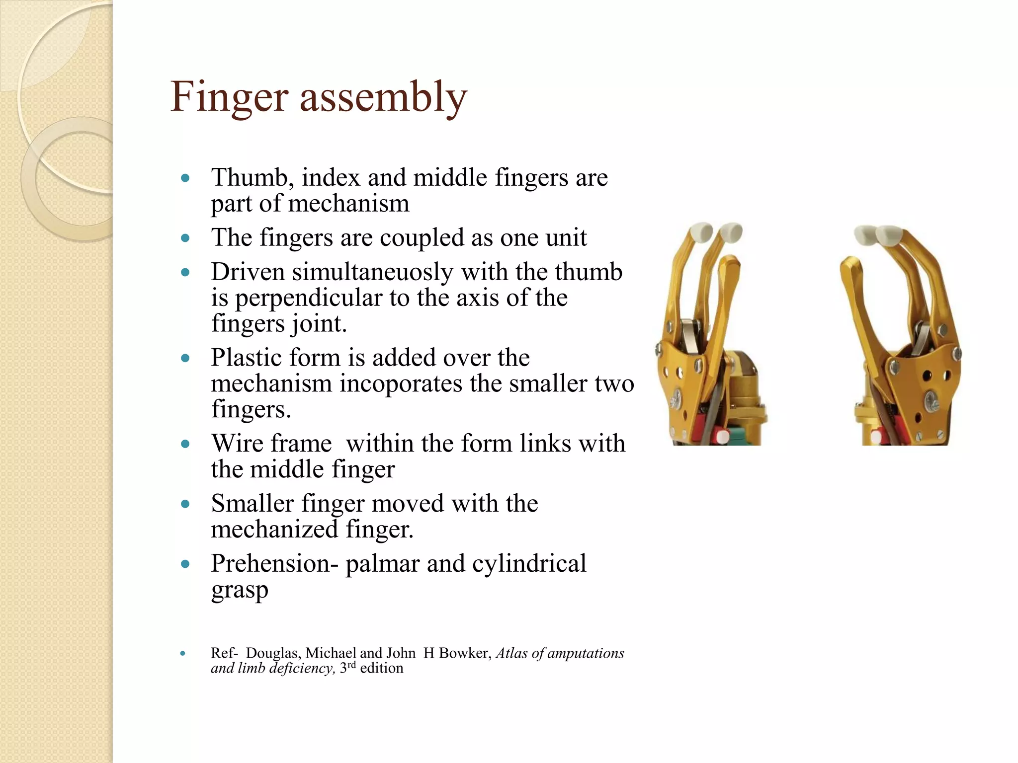
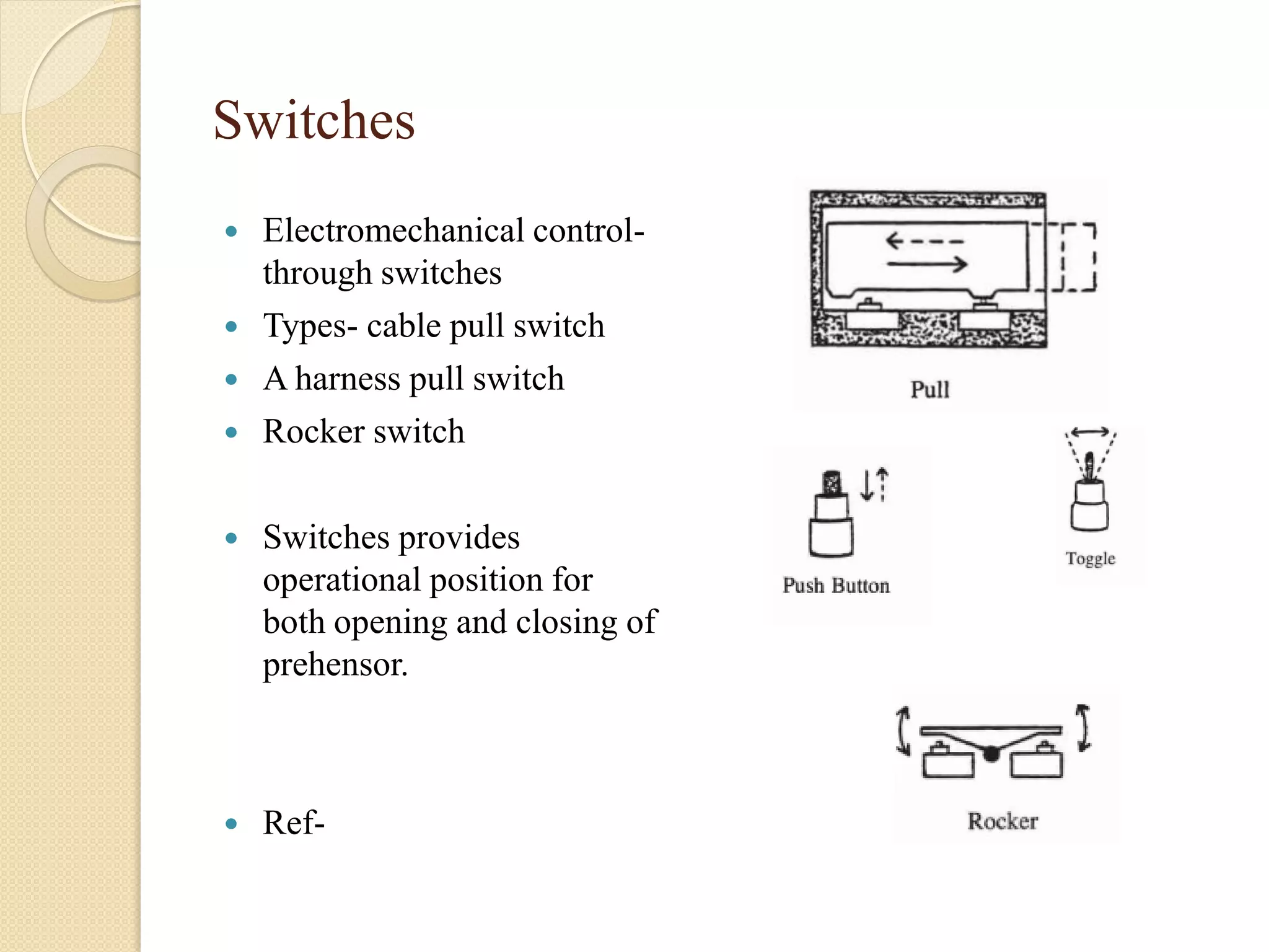
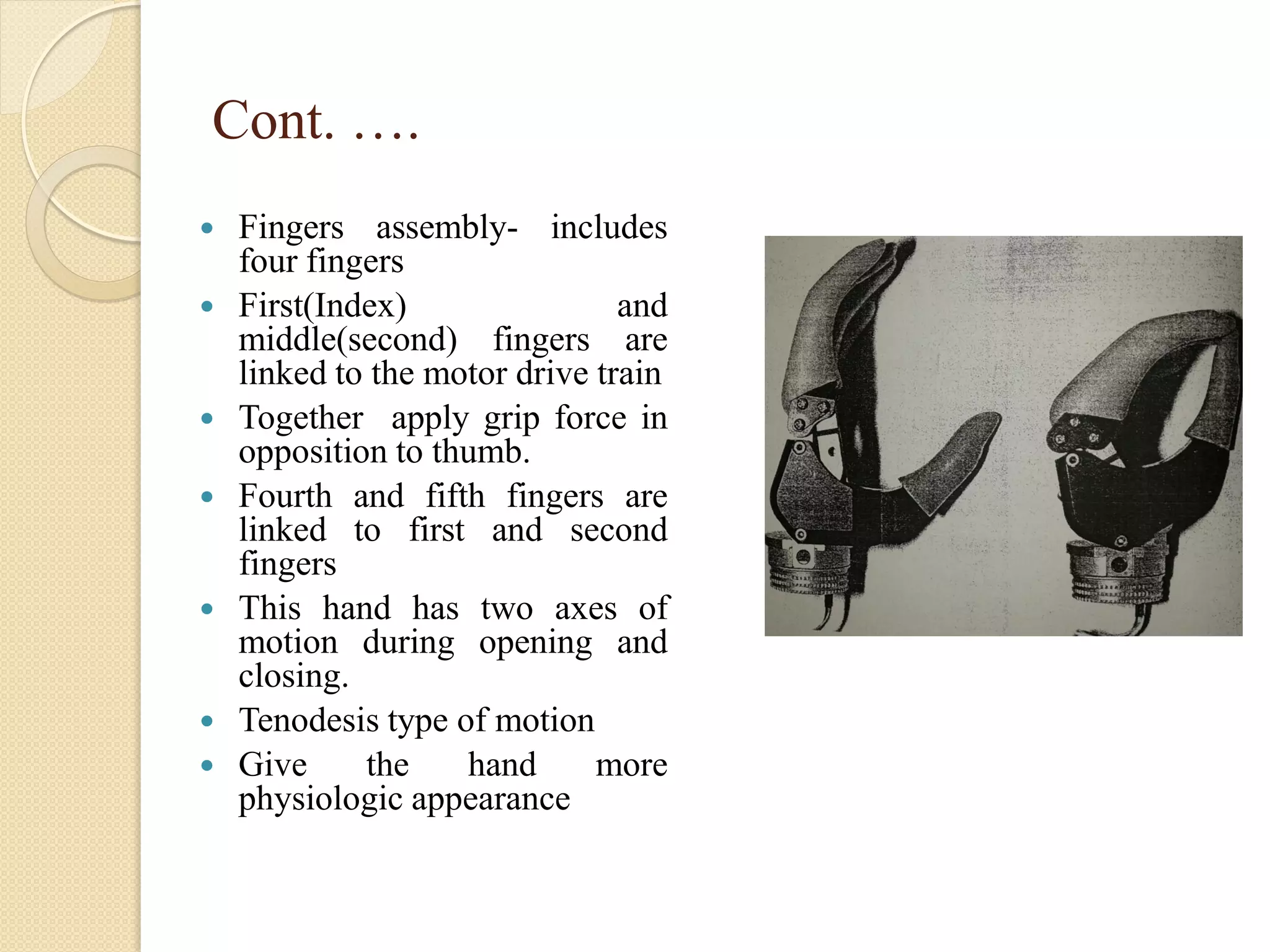
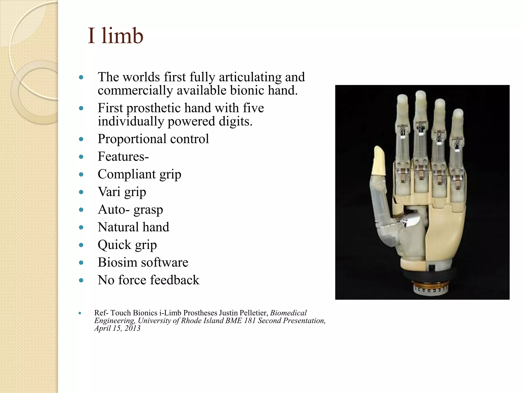
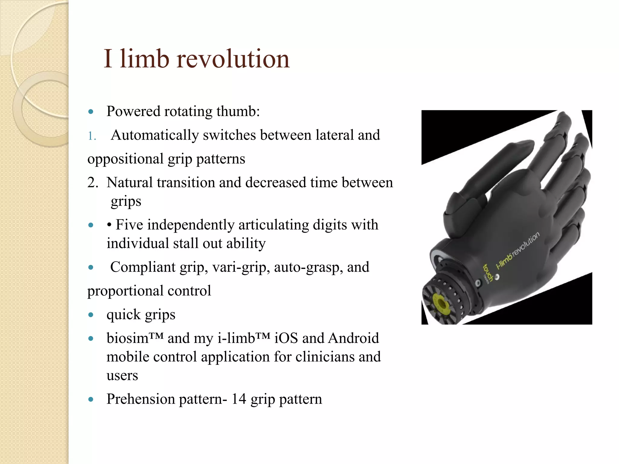
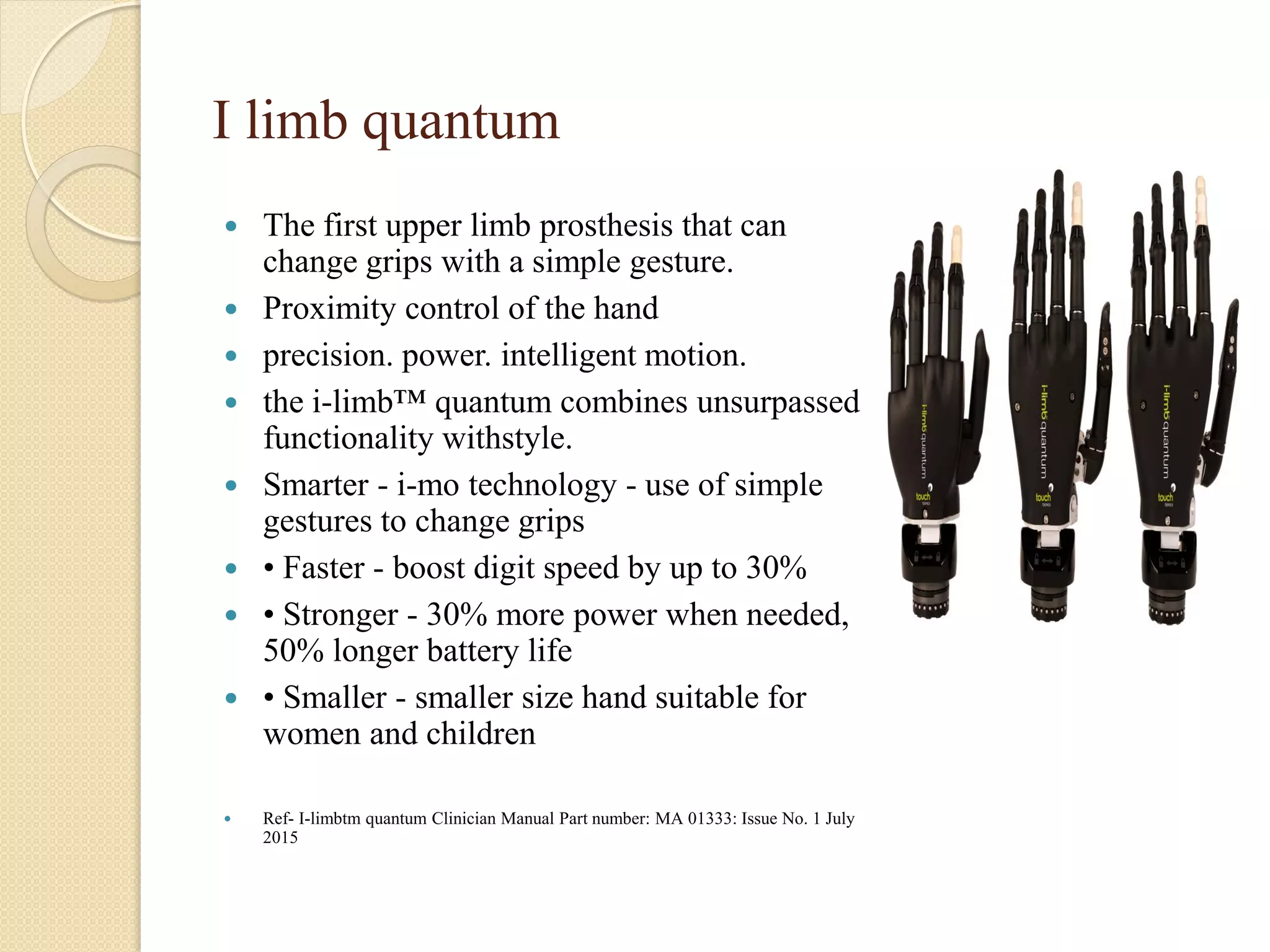
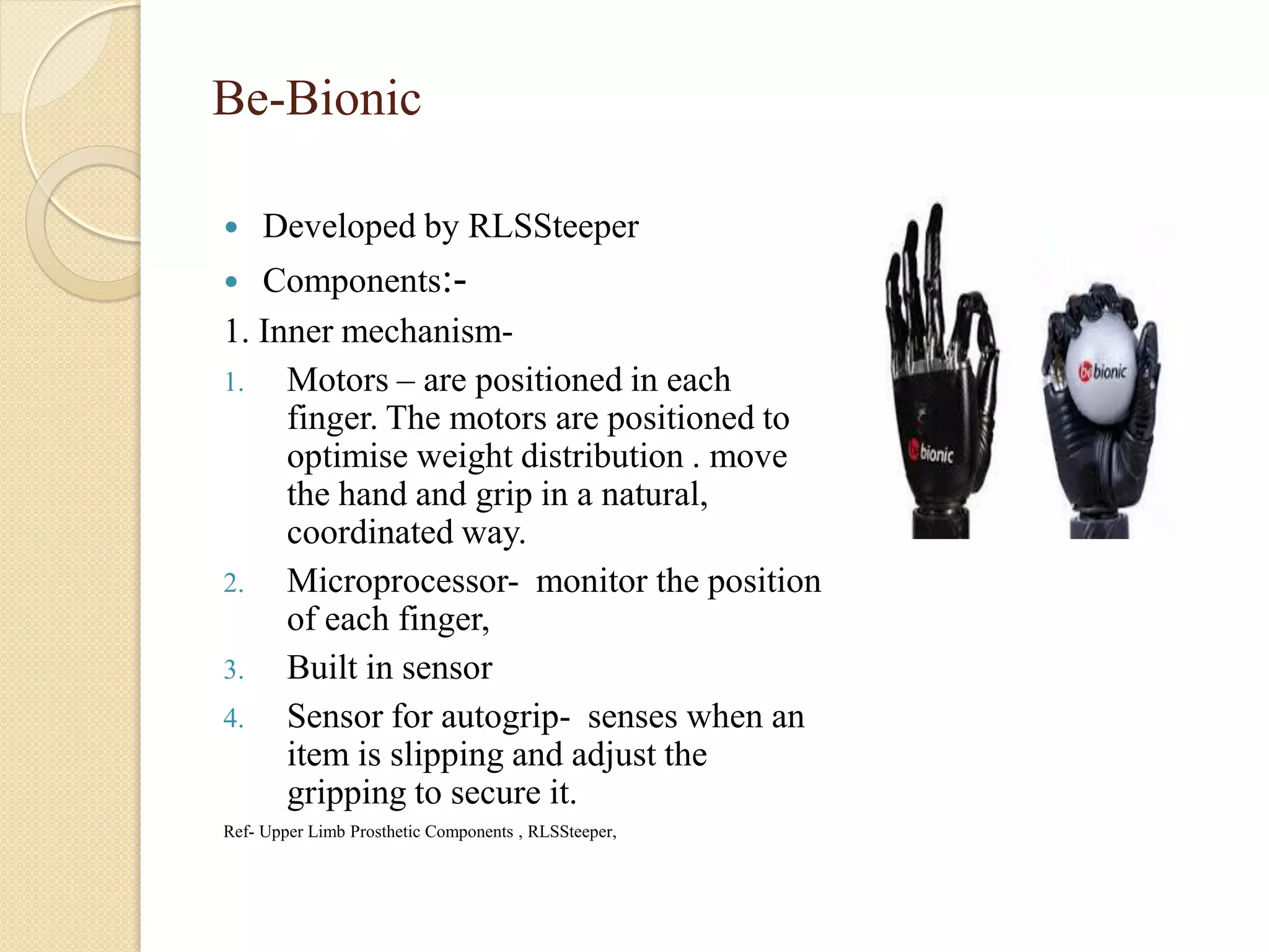
2. Introduction
Electric powered prehension devices are available in variety of
forms, not all resembles anatomic shape.
Single degree of freedom
None of the devices offers independent movement of individual
fingers
All have fixed prehension pattern.
Ref- Douglas, Michael and John H Bowker, Atlas of amputations and limb deficiency, 3rd edition
3. Hands:
• Three fingers, multi-fingers
• Immobile fingers and fingers with one or more finger joints
The human hand
Two muscle sets acts to the hand:
•Extrinsics – located in the forearm
•Intrinsics – located within the hand itself (less powerful)
4. General characteristic of electric terminal
devices
SHAPE-
1. Anatomic
2. Nonanatomic
MECHANICAL CHARACTERISTICS
Prehension force
Width of opening
Speed of movement
Ref- Douglas, Michael and John H Bowker, Atlas of amputations and limb deficiency, 3rd edition
5. Prehension force
Force cited as a figure of merit for prehension devices.
Prehension force capacity, frictional properties of the surfaces in
contact and conformability to surface features contribute to
adequate grip.
Force requirements of prosthetics prehensor based on physiologic
performances.
Prehension forces to a max. of 66.7 N were necessary to carry out a
variety of ADL.
Peizer and associates proposed that this be a minimum standard for
the max. prehensor force of an electric prehensor.
No direct sensory feedback of applied force.
Ref-
1. Douglas, Michael and John H Bowker, Atlas of amputations and limb deficiency, 3rd edition
2. Design of a Human Hand Prosthesis, Project work, WPI
6. Maximum width of opening
Keller and associates, determined that prehensile opening which is
mostly needed-5.1cm but an 8.2cm opening was needed Occasionally.
Piezer and associates, minimum prehensile opening- 8.2cm
which is standard opening adopted by panel on U.E.P.N.R.C.
Prosthetic prehensors having 11.43 cm prehensile opening is wider
opening and it is not used often.
Ref:-
1. Douglas, Michael and John H Bowker, Atlas of amputations and limb deficiency, 3rd edition
2. Joseph T. Belter and Aaron M. Dollar, Performance Characteristics of Anthropomorphic Prosthetic Hands. 2011
IEEE International Conference on Rehabilitation Robotics Rehab Week Zurich, ETH Zurich Science City,
Switzerland, June 29 - July 1, 2011
7. Speed of movement
Piezer and associates- 8.25cm/s measured at the fingertip is a minimum
closure rate,
Physiologic finger speed- 40 rad/s for movement through a range of 75
degree.
If finger length is10cm from MCP to tip – 400cm/s(max)
Upper limit on physiologic finger speed which is far in excess of the
speeds attainable by any prosthetics prehensor.
Average finger velocity in a functional activity- 3 rad/s(179 degree/s)
Max. speed of electric hands are less than the avg. physiologic finger
speed
Prosthetic finger speed based on functional physiologic speeds is
greatly dependent on the control scheme.
Ref:- Joseph T. Belter and Aaron M. Dollar, Performance Characteristics of Anthropomorphic Prosthetic Hands. 2011 IEEE
International Conference on Rehabilitation Robotics Rehab Week Zurich, ETH Zurich Science City, Switzerland, June 29 - July 1, 2011
8. Electric anatomic shape TD
OTTOBOCK SYSTEM ELECTRIC HAND
1. Digital twin hand
2. The DMC plus hand
3. The sensor hand
4. Transcarpal hand
5. System electric hand with no electronics
Centrielectric hand
Motion control hand
RSLSteeper electric hand
BIONIC HAND
1. I limb
2. Bebionic
3. Michelangelo hand
Ref-
1. Douglas, Michael and John H Bowker, Atlas of amputations and limb deficiency, 3rd edition
2. Design of a Human Hand Prosthesis, Project work, WPI
9. Electric Non-anatomic shape TD
Ottobock system electric griefer
Hosmer NU-VA synergetic prehensor
Motion control ETD
RSLSteeper multicontrol powered gripper
Hosmer NY prehension actuator
Ref- Douglas, Michael and John H Bowker, Atlas of amputations and limb deficiency, 3rd edition
10. Common characteristic of Ottobock system
electric hand
Sizes- 7 ¼”, 7 ¾”, 8 ¼”
Parts-
1. Inner mechanism
2. A plastic hand like form
3. Cosmetic glove
Inner mechanism- similar in
configuaration in all models
Includes –
I. electric motor
II. An automatic gear transmission
III. A support structure
IV. Finger assembly
Ref- Douglas, Michael and John H Bowker, Atlas of amputations and limb deficiency, 3rd edition
11. Electric motor
Location - mounted between the
finger assmebly and the wrist at a
right angle the the axis of rotation
of the fingers and thumb.
In line with the long axis of the
forearm
Transcarpal hand- motor
assembly is at right angle w.r.t the
axes of the thumb and fingers,
but shorter and rotated into the
distal palmar region of the hand.
Ref- Douglas, Michael and John H Bowker, Atlas of
amputations and limb deficiency, 3rd edition
12. Finger assembly
Thumb, index and middle fingers are
part of mechanism
The fingers are coupled as one unit
Driven simultaneuosly with the thumb
is perpendicular to the axis of the
fingers joint.
Plastic form is added over the
mechanism incoporates the smaller two
fingers.
Wire frame within the form links with
the middle finger
Smaller finger moved with the
mechanized finger.
Prehension- palmar and cylindrical
grasp
Ref- Douglas, Michael and John H Bowker, Atlas of amputations
and limb deficiency, 3rd edition
13. Automatic gear transmission and drive
mechanism
During finger motion- transmission is in high gear
which allows the fingers and thumb to move at a
maximum speed.
During grasping- transmission remains in high gear
upto 10N prehension force after that it automatically
downshift to drive the finger slower but at a high
torque.
During releasing- transmission must reduce prehension
force while in low gear until it reaches the transition
grip force .
Back lock feature- maintain the prehension force when
the motor is off and to prevent the fingers from
opening.
Slip clutch mechanism- the fingers can be closed or
opened manually.
Ref- Douglas, Michael and John H Bowker, Atlas of amputations and limb deficiency, 3rd edition
14. Current cut off circuit
This circuit senses the motor current and automatically cuts off
power to the motor to avoid a stall condition.
Stall occurs when drive unit has reached its max. o/p torque and
motor stop rotating.
Energy saving features.
Ref- Douglas, Michael and John H Bowker, Atlas of amputations and limb deficiency, 3rd edition
15. Plastic hand like form and cosmetic glove
Fits over the inner mechanism
Incorporates smaller two finger
Gives general hand like shape and
dimension
Improves the grasp
Provides many points of contact
between prehension surface and the
grasped object
16. Digital twin hand
Provide control at constant speed or constant
rate of change of torque.
Control mechanism-
1. Myoelectric control
2. Electromechanical control
1. Myoelectric control mechanism- uses a crisp
threshold strategy
The degree to which the signal exceeds the
threshold does not alter the action of
mechanism.
Ref- Douglas, Michael and John H Bowker, Atlas of amputations and limb deficiency, 3rd edition, pg-
151
17. Switches
Electromechanical control-
through switches
Types- cable pull switch
A harness pull switch
Rocker switch
Switches provides
operational position for
both opening and closing of
prehensor.
Ref-
18. Cont…
The user can control the amount of opening and
closing of the fingers by the length of time the
control signal is maintained
Operation:- two site two function- myoelectrodes
and switch
One site one function- single myoelectrodes
19. The DMC plus hand
Proportional control of speed
of hand and force of gripping
Control scheme- two site two
function by myoelectrodes
Low amplitude signal will
produce a light grip
regardless of how long the
signal is maintained.
Enables the user to gauge the
grip force by sensing how
hard the controlling muscle is
being contracted.
Ref- Douglas, Michael and John H Bowker, Atlas of
amputations and limb deficiency, 3rd edition, pg- 151
20. The sensor hand
Ability to monitor the slip of a
held object and automatically
increase the grip force
1. Slip Sensor – small disklike part,
Force sensitive conductive
plastic overlaid with an array of
electrical contacts
built into palmar surface at the
end of the thumb
Measures 3D force applied to the
thumb tip when an object being
grasped
2. Force transducer strain gauge-
linkage between thumb and
fingers.
21. Mechanism of sensor hand function
Components of thumb force:-
1. Normal force- approximately equal to the grip force produced by sensor
hand.
Applied perpendicular to the face of slip sensor.
2. Tangential force- produced by gravity
Parallel to the surface of slip sensor. That causes an object to slide over
the face of the sensor or slip.
Ratio of tangential force and normal force should be in specific range.
When thumb sensor detects, this ratio exceeds allowed range , the
control electronics activate hand motor to increase grip force.
Second sensor measures the grip force when grasped object not
pressing against thumb sensor.
It allows user to maintain proportional control of grip force.
Ref:- Joseph T. Belter et al, Mechanical design and performance specifications of anthropomorphic prosthetic hands: A review . JRRD ,
Volume 50, Number 5, 2013 Pages 599–618
22. Characteristic Digital twin
hand
DMC plus hand Sensor hand
Avg. max speed 11cm/s 13 cm/s 13cm/s
Max grip force 90N 90N 100N
Max opening
width
10cm 10cm 10cm
Length (7 ¾ “) 14cm 14cm 14cm
Weight (7 ¼ “) 440 g 440gm 440gm
Ref- Douglas, Michael and John H Bowker, Atlas of amputations and limb deficiency, 3rd edition, pg- 148
23. Transcarpal hand
For long residual limb
Does not produce a limb length
discrepancy
Length of the drive unit is
shortened
Rotated it into the distal portion of
the palmar region of the hand and
proximal phalanx of the ring
finger
Base of the hand is base of the
finger chasis
Available in DMC plus control or
digital twin control
24. Cont…
Mechanical Characteristics-
Wt- lighter than DMC plus by 120 gm, 320 gm( 7 ¼ “)
Length- 3.7cm shorter than wrist disarticulation hand
Max, avg speed- 13cm/s
Max. grip force- 90 N
Ref- Douglas, Michael and John H Bowker, Atlas of amputations and limb deficiency, 3rd edition, pg- 151-152
25. System electric hand with no electronics
Electric connection to this hand is directly
to the motor leads through on/off switch.
Used with electronics controller from
other manufacturer
Performances characteristic will depend
on the particular electronics driving the
hand and the voltage of the battery.
No current cut off circuit.
Ref- Douglas, Michael and John H Bowker, Atlas of amputations and limb
deficiency, 3rd edition, pg- 152
26. Centrielectric hand
Lightest and shortest electric hand
Components-
1. Articulated mechanism,
2. A hand shaped inner form
3. A cosmetic glove
Articulated mechanism-
Incorporates two motor design
1st motor- drives the fingers open
and shut against a stationary thumb
2nd motor- locks the finger to
maintain grip force.
Locking motor is not powered
when the fingers are locked in place
27. Cont. ….
Fingers assembly- includes
four fingers
First(Index) and
middle(second) fingers are
linked to the motor drive train
Together apply grip force in
opposition to thumb.
Fourth and fifth fingers are
linked to first and second
fingers
This hand has two axes of
motion during opening and
closing.
Tenodesis type of motion
Give the hand more
physiologic appearance
28. Cont….
Electronic controller is a separate unit not bulit into the hand.
Operated with myoelectrodes or force sensing resistors
Provides proportional control of speed and rate of change of grip
force.
Ref- Douglas, Michael and John H Bowker, Atlas of amputations and limb deficiency, 3rd edition, pg- 152- 153
29. Motion control hand
Version-
1. standard
2. Short
3. With wrist flexion unit
4. With a built in
controller(prohand)
Components-
1. The mechanism
2. Hand shaped inner form
3. Cosmetic glove
Ref- Douglas, Michael and John H Bowker, Atlas of
amputations and limb deficiency, 3rd edition, pg- 153-
154
30. Cont…
Inner mechanism:-
Transverse mounted motor and automatic gear
transmission driving the thumb and first two
fingers in opposition.
Two fingers are linked together to move as a
single unit.
Safety release feature- on/off switch mounted
below the finger assembly
Switch is pushed all the way in from the back of
the hand, fingers are disengaged from the gear
train and can be opened manually
Automatic gear transmission- provides fast speed
in high gear when the fingers are moving freely
High torque in low gear when fingers are closed
on an object.
Current cut off circuit feature to prevent the
motor from being powered in stall.
Except prohand other hand requires external
control module
32. Short hand version
Reduces the length of the standard size 7 ¾‘” by 1,3 cm
The amount of shortening is slightly less for size 7 ¼”
Slightly more for the size 8 ¼”
Ref- Douglas, Michael and John H Bowker, Atlas of amputations and limb deficiency, 3rd edition, pg- 153- 154
33. Motion control hand with a flexion wrist
Flexion mechanism is built into the drive assembly and wrist
connector
Added length and weight over that of the standard size 7 ¾” by 0.3
cm and 48 gm respectively
Hand can be locked in three positions- neutral , 30 degree flexion
and extension
Spring loaded push plate- positioned on the back of the hand near
the base
Lock is released manually
Ref- Douglas, Michael and John H Bowker, Atlas of amputations and limb deficiency, 3rd edition, pg- 153- 154
34. Motion control hand with a built in controller
Requires only connection of battery and myoelectrodes at the wrist
connector
It has procontrol 2 electronic controller built into the hand
Procontrol 2 also available as a separate control module and
provides proportional myoelectric control of speed and rate of
change of grip force
Ref- Douglas, Michael and John H Bowker, Atlas of amputations and limb deficiency, 3rd edition, pg- 153- 154
35. RSLSteeper electric hand
Multicontrol plus electric hand
Components-
1. Finger assembly
2. Inner Mechanism
3. Hand shaped shell encircled the mechanism
proximal to fingers
4. Cosmetic glove
Finger assembly-
Thumb, index and middle fingers are molded of
hard plastic directly over the armature of the
finger assembly
Lined with a soft elastomeric material on the
palmar surface
Deforms and shapes itself to the contact surface
of held objects.
Ref- Douglas, Michael and John H Bowker, Atlas of amputations and limb
deficiency, 3rd edition, pg- 154- 155
36. Cont…
Inner mechanism-
1. Incorporates single motor with gear
reducer
2. Drive screw
3. Nut actuator
All held within a support structure
The first two fingers(one unit) and thumb
linked to the nut and to stationary
support structure
As the nuts travels along the screw the
fingers and thumb pivot and move in
palmar prehension pattern
Electronic controller- built into the
hand
Motor cut off circuit features available
37. Control mode
Five control options
1. Three are available – single site, two functions control
This three options differ-
Close automatically
Close at constant speed
Close at a speed proportional to the magnitude of signal
2. Fourth and fifth options- two site two function control using
independent control source
Inputs from- switch and myoelectrodes
Ref- Douglas, Michael and John H Bowker, Atlas of amputations and limb deficiency, 3rd edition, pg- 154- 155
38. Characteristic Centrielectric hand Motion control
hand
RLS Steeper
hand
Size- 7 ¼”, 7 ¾” 7 ¼”, 7 ¾”, 8 ¼”, 7 ¼”, 7 ½” ,7 ¾”,
6 ¾”
Length- 7 ¾”, 2.5 cm shorter
than transcarpal
hand
13.7cm(7 ¾”) 13.7cm (all sizes)
Wt- 250 gm for 7 ¾” 433gm(7 ¾”) 370gm(7 ¾”)
Max opening
width-
7.6cm(7 ¾) 10( sz-7 ¾) 7cm
Max grip
force-
81N (7 ¾) 98.1 N 55 to 65 N
Max speed of
movement-
10cm/s 10.7 cm/s at 7.2v 8.75 cm/s
Ref- Douglas, Michael and John H Bowker, Atlas of amputations and limb deficiency, 3rd edition, pg- 148
39.
40. I limb
The worlds first fully articulating and
commercially available bionic hand.
First prosthetic hand with five
individually powered digits.
Proportional control
Features-
Compliant grip
Vari grip
Auto- grasp
Natural hand
Quick grip
Biosim software
No force feedback
Ref- Touch Bionics i-Limb Prostheses Justin Pelletier, Biomedical
Engineering, University of Rhode Island BME 181 Second Presentation,
April 15, 2013
41. versions
I-limb ultra
I-limb revolution
I limb ultra revolution
I limb quantum
I limb digits
42. I limb ultra
Components-
Five, individually powered,
articulating fingers
Manually rotatable thumb to
create different grasping options
Manually rotatable wrist, or can
be integrated with an electronic
wrist rotator
Aluminium chassis for durability
Ref- Key Features_ I-limb ultra _ Touch Bionics.html
43. I limb revolution
Powered rotating thumb:
1. Automatically switches between lateral and
oppositional grip patterns
2. Natural transition and decreased time between
grips
• Five independently articulating digits with
individual stall out ability
Compliant grip, vari-grip, auto-grasp, and
proportional control
quick grips
biosim™ and my i-limb™ iOS and Android
mobile control application for clinicians and
users
Prehension pattern- 14 grip pattern
44. Control options-
Proportional control - the stronger the input signal, the faster the
fingers move
Five available control strategies - two dual-site and three single-site
1. Dual site Differential
2. Dual site First Over
3. Single site Voluntary Close
4. Single site Voluntary Open
5. Single site Alternating
Ref:- I-limb revolution _ Touch Bionics.html
45. I limb ultra revolution
Individually motorized digits and thumb,
stall detection and the unique biosim
software used to control the i-limb ultra
revolution
compliant grip through individually
powered digits with stall out ability.
A powered rotating thumb I conjunction
with a pulsing,
An anti-drop safety feature (auto-grasp)
the wide range of automated grip
patterns lead to broad functionality
Grip pattern- 24 grip pattern through
triggerring different muscles
Ref- I-limbtm ultra revolution Clinician Manual Part number: MA01140: Issue
No. 4, December 2014
46. I limb quantum
The first upper limb prosthesis that can
change grips with a simple gesture.
Proximity control of the hand
precision. power. intelligent motion.
the i-limb™ quantum combines unsurpassed
functionality withstyle.
Smarter - i-mo technology - use of simple
gestures to change grips
• Faster - boost digit speed by up to 30%
• Stronger - 30% more power when needed,
50% longer battery life
• Smaller - smaller size hand suitable for
women and children
Ref- I-limbtm quantum Clinician Manual Part number: MA 01333: Issue No. 1 July
2015
47. I-limb digit
i-limb digits is the fully
customized electronic prosthesis
for people with missing fingers or
partial hands.
These digits, which move
independently and bend at the
joints, work in conjunction with
any remaining fingers to help you
increase your functional
capabilities.
Control – Remote electrode, FSR
or Standard electrode
Ref- I-limb digits Clinician Manual, Touch Bionic, Part
number: MA01064: Issue No. 2, December 2014
48. Cont…
Site selection-
1. Hypothenar compartment
2. Thenar compartment
3. Dorsum of the hand
Grip pattern- 14
Ref- I-limb digits Clinician Manual, Touch Bionic, Part number: MA01064: Issue No. 2, December 2014
49. Be-Bionic
Developed by RLSSteeper
Components:-
1. Inner mechanism-
1. Motors – are positioned in each
finger. The motors are positioned to
optimise weight distribution . move
the hand and grip in a natural,
coordinated way.
2. Microprocessor- monitor the position
of each finger,
3. Built in sensor
4. Sensor for autogrip- senses when an
item is slipping and adjust the
gripping to secure it.
Ref- Upper Limb Prosthetic Components , RLSSteeper,
50. Cont…
2. Finger assembly- thumbs position
selectable, thumb is wider.
fingers are foldable and covered
with soft pad,
3. Cosmetic glove
Grip pattern – 14 grip pattern
Control scheme- proportional
control
Wrist options-
1. quick disconnect
2. Multiflex
3. Flexion wrist
4. Short wrist
51. Michelangelo hand
The Michelangelo Hand built by
Advanced Arm Dynamics is simply the
most advanced hand on the market today
in prosthetics.
It actually has the powered opposable
thumb,
The hand is equipped with two drive units
The fingers are made up of hard and soft
materials and model bones, joints,
muscles, and tendons.
The new oval wrist adapter also appears
much more natural and permits pronation
and supination of the wrist joint .
Ref-
www.hanger.com/prosthetics/services/technology/pages/michelangelohand.aspx
52. Finger mechanism
Ref:- Joseph T. Belter et al, Mechanical design and performance specifications of anthropomorphic prosthetic hands: A review . JRRD , Volume 50,
Number 5, 2013 Pages 599–618
53. General characteristic of bionic hand
Characteristic I limb Be-bionic Michelangelo
Weight(g) 460-465 495-539 420(approx)
No. Of joints 11 11 6
DOF 6 6 2
No. of actuator 5 5 2
Joint coupling
method
Tendon
linking
MCP to
PIP jt
Linkage spanning
MCP to PIP jt
Cam design with links
to all fingers
Actuation method DC motor-
worm gear
DC motor- lead
screw
-
Adaptive grip yes yes No
Ref:- Joseph T. Belter et al, Mechanical design and performance specifications of anthropomorphic prosthetic
hands: A review . JRRD , Volume 50, Number 5, 2013 Pages 599–618
54. Literature review
1. Van Der Niet OV et al, compares the functionality of the i-LIMB
to the DMC plus hand, the power grip of the i-LIMB equals the
power grip of the DMC plus hand, which was of great value to the
prosthesis user.
2. Artem Kargov et al, The adaptive prosthetic hand exerts low
contact forces during grasping, which are spread over a wide
contact area, and also the pattern of force distribution resembles
the human hand. Due to their construction, non-adaptive
prostheses exert high grip forces that are concentrated on a small
contact area
Ref-
1. Olga van der Niet; Raoul M. Bongers, Corry K. van der Sluis, Functionality of i-LIMB and i-LIMB Pulse hands: Case
report, JRRD, Volume 50, Number 8, 2013
2. Artem Kargov et al, A comparison of the grip force distribution in natural hands and in prosthetic hands, Disability and
rehabilitation, 2004; VOL. 26, NO. 12, 705–711
55. References
Douglas, Michael and John H Bowker, Atlas of amputations and limb
deficiency, 3rd edition
John N. Billock, C.P.O. Upper Limb Prosthetic Terminal Devices:
Hands Versus Hooks, Clinical prosthetics and orthotics, vol-10. no-2.
pp-57-65
Joseph T. Belter, Jacob L. Segil; Aaron M. Dollar, richard F. Weir,
Mechanical design and performance specifications anthropomorphic
prosthetic hands: A review , JRRD , volume 50, number 5, 2013 pages
599–618
Olga van der Niet; Raoul M. Bongers, Corry K. van der Sluis,
Functionality of i-LIMB and i-LIMB Pulse hands: Case report, JRRD,
Volume 50, Number 8, 2013
Artem Kargov et al, A comparison of the grip force distribution in
natural hands and in prosthetic hands, Disability and rehabilitation,
2004; VOL. 26, NO. 12, 705–711
Touch Bionics i-Limb Prostheses Justin Pelletier, Biomedical
Engineering, University of Rhode Island BME 181 Second
Presentation, April 15, 2013
56. Design of a Human Hand Prosthesis, Project work, WPI
Joseph T. Belter and Aaron M. Dollar, Performance Characteristics of
Anthropomorphic Prosthetic Hands. 2011 IEEE International Conference on
Rehabilitation Robotics RehabWeek Zurich, ETH Zurich Science City,
Switzerland, June 29 - July 1, 2011