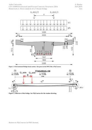
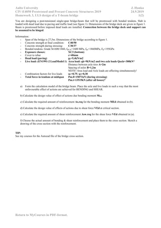
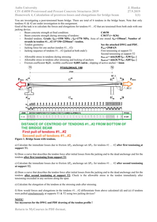
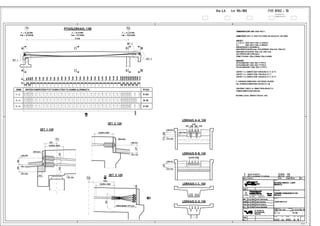
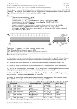
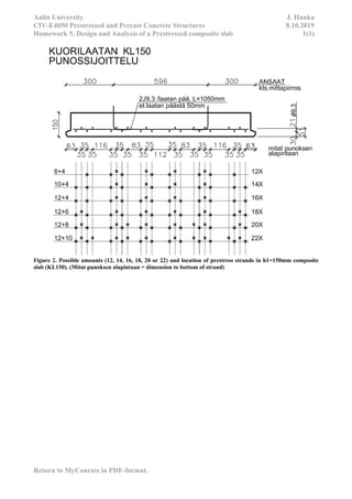
Aalto University Janne Hanka
CIV-E4050 Prestressed concrete structures 10-Oct-19
Homework assignments and solutions, 2019
All rights reserved by the author.
Foreword:
This educational material includes assignments of the course named CIV-E4050 Prestressed
concrete from the 2019. Course is part of the Master’s degree programme of Structural Engineering
and Building Technology in Aalto University.
Each assignment has a description of the problem and the model solution by the author. Description
of the problems and the solutions are in English. European standards EN 1990 and EN 1992-1-1 are
applied in the problems.
Questions or comments about the assignments or the model solutions can be sent to the author.
Author: MSc. Janne Hanka
janne.hanka@aalto.fi / janne.hanka@alumni.aalto.fi
Place: Finland
Year: 2019
Table of contents:
Homework 1. Design of crane foundation using post-tensioned rock anchors
Homework 2. SLS Analysis of a post-tensioned bridge beam
Homework 3. ULS design of a post-tensioned bridge beam
Homework 4. Calculation of prestress losses and elongations for a post-tensioned bridge beam
Homework 5. Design of precast composite slab
Aalto University J. Hanka
CIV-E4050 Prestressed and Precast Concrete Structures 2019 11.9.2019
Homework 1, Design of crane foundation anchoring 1(2)
Return to MyCourses in PDF-format.
You are designing rock anchoring of a crane foundation using strand anchors. The design requirement given
for the structure is that the foundation steel plates has to be fully stressed (loss of contact between bottom of
foundation steel plates and bedrock is not allowed!).
Figure 1. Crane and layout of crane legs (not in scale)
Crane dimensions and weight:
- Crane tower height H=67m and weight = 60 000kg
- Crane beam length acc. to figure 1. Crane beam weight = 40 000kg
- Load at the end of crane beam is 4 000kg
- Spacing of crane legs is L2=2050mm (see figure 2)
- Strands ancrhos to be used: fpk=1860MPa Ap=150mm^2, more details see figure 3 & 4.
a) Calculate the maximum support reactions (loading point 1,2,3,4) at the foundation level.
b) Calculate the required anchoring force for one crane leg.
c) Choose the amount and type of anchors for one leg (see figure 2). *
d) Choose the prestressing (jacking) force Pmax. Calculate the force that remains in one anchor after locking
Pm.0. You can assume that the free stressing length is 4m and slippage of anchors is 4,5mm.
f) Draw a sketch of your design that showing the anchoring plan and jacking force(s).
A A
Aalto University J. Hanka
CIV-E4050 Prestressed and Precast Concrete Structures 2019 11.9.2019
Homework 1, Design of crane foundation anchoring 2(2)
Return to MyCourses in PDF-format.
*Tip: Make an educated guess and revise you design if needed.
Figure 2. Steel plates used to connect the crane legs to the anchoring strands.
Aalto University J. Hanka
CIV-E4050 Prestressed and Precast Concrete Structures 2019 11.9.2019
Homework 1, Design of crane foundation anchoring 3(2)
Return to MyCourses in PDF-format.
https://www.naulankanta.fi/files/bmvit-327120_0018_14_anp_-_strand_anchor_en.pdf
Figure 3. Allowable jacking forces.
Figure 4. Strand anchor.
Aalto University J. Hanka
CIV-E4050 Prestressed and Precast Concrete Structures 2016 18.9.2019
Homework 2, Stress analysis of a T-beam bridge 1(1)
Return to MyCourses in PDF-format.
You are designing a post-tensioned single-span bridge-beam that will be prestressed with bonded tendons. Slab is
loaded with dead load due to paving and traffic load (see figure 1). Dimensions of the bridge deck are given in figure 1.
Beam is prestressed before imposed dead loads are installed. Connection between the bridge deck and support can
be assumed to be hinged.
Information:
- Span of the bridge is 27,5m. Dimensions of the bridge according to figure 1.
- Concrete strength at final condition: C40/50
- Concrete strength during stressing: C30/37
- Bonded tendons. Grade St1600/1860, fp0,1k=1600 MPa, fpu=1860MPa, Ep=195GPa
- Exposure classes: XC3 (bottom)
- Dead load (paving) gk=5,4kN/m2
- Live load: (EN1991-2 LoadModel 1) Area load: qk=9kN/m2 and two axle loads Qaxle=300kN*
Distance between axle tires A=2m
Spacing of axles B=1,2m
NOTE! Area load and Axle loads are affecting simultaneously!
- Combination factors for live loads ψ1=0,75; ψ2=0,30
- Total force in tendons at midspan Pm.0=15071kN (during stressing)
Pm.t=13519kN (after all losses)
a) Form the calculation model of the bridge beam. Calculate the effect of actions due to selfweight, dead load
and live load at midspan.
NOTE! Place the axle and live loads in such a way that the most unfavourable effect of actions are reached at
midspan between modules T1 and T2.
b) Calculate the effective flange width (beff) according to EN 1992-1-1 chapter 5.3.2.1(2).
c) Calculate the cross section properties to be used in the stress analysis:
- Moment of inertia and cross section area Igr, Agr
d) Check that the allowable stresses given in table 1 are not exceeded in critical section at midspan.
e) Calculate the deflection for quasi-permanent combination Δqp. Check that the allowable deflection given in
table 1 is not exceeded. Calculate the beam is shortening due to prestress also.
Table 1. Allowable stresses of concrete in serviceability limit state (SLS) for unbonded tendons.
Condition # Combination EN1990 Limitation EC2 Clause
Initia
l
I Max tension Initial σct.ini < fctm.i
II Max compression Initial σcc.ini < 0,6*fck.i 5.10.2.2(5)
Final
III Max tension Frequent σct.f < fctm
IIIb Max tension Quasi-permanent σct.qp < 0 * 7.3.1(5)
IV Max compression Characteristic σcc.c < 0,6*fck 7.2(2)
IVb Max compression Quasi-permanent σcc.c < 0,45*fck 7.2(3)
Max deflection Quasi-permanent
Creep factor = 2
Δ < Span / 250 7.4.1(4)
Max crack width Frequent wk.max < 0,2mm 7.3.1(5)
* Bonded tendons require decompression (vetojännityksettömyys) for quasi-permanent combination.
TIP C:
Use the Autocad REGION and MASSPROP commands to find the Igr and Agr.
Tip for (c), (d):
http://www.adaptsoft.com/resources/ADAPT_T901_Effective-Width-PT-beamsr.pdf
Aalto University J. Hanka
CIV-E4050 Prestressed and Precast Concrete Structures 2016 18.9.2019
Homework 2, Stress analysis of a T-beam bridge 1(1)
Return to MyCourses in PDF-format.
Figure 1. Post-tensioned Bridge-beam section. Also given in the DWG file at MyCourses
Figure 2. Sideview of the bridge. See MyCourses for the tendon drawing.
Aalto University J. Hanka
CIV-E4050 Prestressed and Precast Concrete Structures 2019 24.9.2019
Homework 3, ULS design of a T-beam bridge 1(2)
Return to MyCourses in PDF-format.
You are designing a post-tensioned single-span bridge-beam that will be prestressed with bonded tendons. Slab is
loaded with dead load due to paving and traffic load (see figure 1). Dimensions of the bridge deck are given in figure 1.
Beam is prestressed before imposed dead loads are installed. Connection between the bridge deck and support can
be assumed to be hinged.
Information:
- Span of the bridge is 27,5m. Dimensions of the bridge according to figure 1.
- Concrete strength at final condition: C40/50
- Concrete strength during stressing: C30/37
- Bonded tendons. Grade St1600/1860, fp0,1k=1600 MPa, fpu=1860MPa, Ep=195GPa
- Exposure classes: XC3 (bottom)
- Cover to rebar c=40mm
- Dead load (paving) gk=5,4kN/m2
- Live load: (EN1991-2 LoadModel 1) Area load: qk=9kN/m2 and two axle loads Qaxle=300kN*
Distance between axle tires A=2m
Spacing of axles B=1,2m
NOTE! Area load and Axle loads are affecting simultaneously!
- Combination factors for live loads ψ1=0,75; ψ2=0,30
- Total force in tendons at midspan Pm.0=15071kN (during stressing)
Pm.t=13519kN (after all losses)*
a) Form the calculation model of the bridge beam. Place the axle and live loads in such a way that the most
unfavourable effect of actions are achieved for BENDING and SHEAR.
b) Calculate the design value of effect of actions due bending moment MEd.
c) Calculate the required amount of reinforcement As.req for the bending moment MEd obtained in (b).
d) Calculate the design value of effects of actions due to shear force VEd at critical section.
e) Calculate the required amount of shear reinforcement Asw.req for the shear force VEd obtained in (a).
f) Choose the actual amount of bending & shear reinforcement and place them to the cross section. Sketch a
drawing of the cross section with the reinforcement.
TIP:
See my courses for the Autocad file of the bridge cross section.
Aalto University J. Hanka
CIV-E4050 Prestressed and Precast Concrete Structures 2019 24.9.2019
Homework 3, ULS design of a T-beam bridge 1(2)
Return to MyCourses in PDF-format.
Figure 1. Post-tensioned Bridge-beam section. Also given in the DWG file at MyCourses
Figure 2. Sideview of the bridge. See MyCourses for the tendon drawing.
Aalto University J. Hanka
CIV-E4050 Prestressed and Precast Concrete Structures 2019 27.9.2019
Homework 4, Calculation of prestress losses and elongations for bridge beam 1(1)
Return to MyCourses in PDF-format.
You are investigating a post-tensioned beam bridge. There are total of 6 tendons in the bridge beam. Note that only
tendons #1 & #2 are under investigation in this assignment.
Goal of the task is to calculate the forces and elongations for tendons #1…#2 that are tensioned from both ends with one
jacking device.
- Beam concrete strength at final condition: C40/50
- Beam concrete strength during stressing of tendons: C30/37 (=~K36)
- Bonded tendons. Grade: fp0,1=1550 MPa ; fpk=1770 MPa. Area of one strand Ap1=150mm2
. Number of
strands in tendon #1…#2 15*150=2250mm2
/ tendon.
- Tendon geometry: See the attached DWG and PDF.
- Jacking force for one anchor (tendon #1…#2) Pmax=2948 kN
- Jacking sequence of tendons #1…#2 (jacked at both ends!): First tensioning at support T1
Second tensioning at support T2
- Allowable stress in tendons during stressing σmax.all = min{0,80 fpk ; 0,90 fp0,1 }
- Allowable stress in tendons after stressing and locking of anchors σpm0.all = min{0,75 fpk ; 0,85 fp0,1 }
- Friction coefficient=0,21 ; wobble coefficient=0,005 rad/m ; slipping of active anchor = 6mm
Figure 1. Bridge beam with tendons.
a) Calculate the immediate losses due to friction ΔPμ, anchorage set ΔPsl. for tendons #1 … #2 after first tensioning at
support T1.
b) Draw a curve that describes the tendon force after initial losses from the jacking end to the dead anchorage end for the
tendons after first tensioning from support T1.
c) Calculate the immediate losses due to friction ΔPμ, anchorage set ΔPsl. for tendons #1 … #2 after second tensioning
at support T2.
d) Draw a curve that describes the tendon force after initial losses from the jacking end to the dead anchorage end for the
tendons after second tensioning at support T2. Check is the allowable stress in the tendon immediately after
tensioning exceeded in any sections along the span.
e) Calculate the elongation of the tendons at the stressing ends after stressing.
f) How would forces and elongations in the tendons #1…#2 differentiate from above calculated (d) and (e) if tendons
were pulled simultaneously at supports T1 & T2 using two jacking devices?
NOTE!
See mycourses for the DWG and PDF drawing of the tendon profile !
Pmax Pmax
B
Aalto University J. Hanka
CIV-E4050 Prestressed and Precast Concrete Structures 8.10.2019
Homework 5, Design and Analysis of a Prestressed composite slab 1(1)
Return to MyCourses in PDF-format.
Slab in figure 1 is prestressed with pre-tensioned bonded tendons. Strength class of the prestressed slab is C40/50.
Topping of C30/37 shall be casted on top of the slab. Prestressed slab is not propped during casting of topping, see
figure 1. Structure is loaded with a live load qk and imposed dead load gk.
Information:
- Composite slab concrete strength: C40/50 ;
- Surface slab concrete strength: C30/37 ;
- Exposure classes XC3, XF1. Design working life: 50 years. Consequence class CC2
- Bonded tendons. Grade Y1860S7 diameter=9,3mm (fp0,1k/fpk=1640MPa/1860MPa)
- Stress of tendons at release σmax=1200MPa
- Long term losses due to creep, shrinkage and relaxtation of tendons can be assumed Δσ=100MPa
- Area of one tendon Ap1=52mm2
. Number of tendons may vary from 12 to 22 (see figure 2)
- Liveload qLL=2,5 kN/m2. Combination factors: ψ0=0,7; ψ1=0,5; ψ2=0,3 (EN 1990 Class G, garages)
- Imposed dead load gk=0,5 kN/m2
Figure 1. Prestressed composite slab.
a) Choose the amount np and corresponding eccentricity ep of tendons according to figure 2. Calculate the cross
section properties of the prestressed slab (without composite action) using method of transformed section in SLS.
b) Calculate the cross section properties of the composite section using method of transformed section in SLS.
c) Calculate the bottom stress of the concrete section at midspan (x=L/2) immediately after casting of surface slab
d) Check that the allowable stresses given in table 1 are not exceeded in SLS at midspan when the final live load is
affecting. How the design should be improved if any of the allowable stresses are exceeded?
e) Calculate the deflection for quasi-permanent combination Δqp. Check that the allowable deflection given in table
1 is not exceeded. Calculate the beam is shortening due to prestress.
f) Calculate the design bending moment MEd in ULS and the bending moment resistance of the composite structure
MRd in ULS. Is the bending moment resistance of the structure adequate in ULS?
Table 1. Allowable stresses of concrete in serviceability limit state (SLS) for bonded tendons in XC3.
Condition # Combination EN1990 Limitation EC2 Clause
Initia
l
I Max tension Initial σct.ini < fctm.i
II Max compression Initial σcc.ini < 0,6*fck.i 5.10.2.2(5)
Final
III Max tension Frequent σct.f < fctm
IIIb Max tension Quasi-permanent σct.qp < 0 * 7.3.1(5)
IV Max compression Characteristic σcc.c < 0,6*fck 7.2(2)
IVb Max compression Quasi-permanent σcc.c < 0,45*fck 7.2(3)
Max deflection Quasi-permanent
Creep factor = 2
Δ < Span / 250 7.4.1(4)
Max crack width Frequent wk.max < 0,2mm 7.3.1(5)
*Note: Bonded tendons require decompression (vetojännityksettömyys) for quasi-permanent combination.
Geometry: L=7000mm ; bw=1200m ; (span and width of slab)
h1=150mm (height of composite precast slab);
h2=150mm (height of cast-in-situ slab); ep= (eccentricity of tendons)
Aalto University J. Hanka
CIV-E4050 Prestressed and Precast Concrete Structures 8.10.2019
Homework 5, Design and Analysis of a Prestressed composite slab 1(1)
Return to MyCourses in PDF-format.
Figure 2. Possible amounts (12, 14, 16, 18, 20 or 22) and location of prestress strands in h1=150mm composite
slab (KL150). (Mitat punoksen alapintaan = dimension to bottom of strand)

Prestressed concrete course assignments 2019

  • 1.
    Aalto University JanneHanka CIV-E4050 Prestressed concrete structures 10-Oct-19 Homework assignments and solutions, 2019 All rights reserved by the author. Foreword: This educational material includes assignments of the course named CIV-E4050 Prestressed concrete from the 2019. Course is part of the Master’s degree programme of Structural Engineering and Building Technology in Aalto University. Each assignment has a description of the problem and the model solution by the author. Description of the problems and the solutions are in English. European standards EN 1990 and EN 1992-1-1 are applied in the problems. Questions or comments about the assignments or the model solutions can be sent to the author. Author: MSc. Janne Hanka janne.hanka@aalto.fi / janne.hanka@alumni.aalto.fi Place: Finland Year: 2019 Table of contents: Homework 1. Design of crane foundation using post-tensioned rock anchors Homework 2. SLS Analysis of a post-tensioned bridge beam Homework 3. ULS design of a post-tensioned bridge beam Homework 4. Calculation of prestress losses and elongations for a post-tensioned bridge beam Homework 5. Design of precast composite slab
  • 2.
    Aalto University J.Hanka CIV-E4050 Prestressed and Precast Concrete Structures 2019 11.9.2019 Homework 1, Design of crane foundation anchoring 1(2) Return to MyCourses in PDF-format. You are designing rock anchoring of a crane foundation using strand anchors. The design requirement given for the structure is that the foundation steel plates has to be fully stressed (loss of contact between bottom of foundation steel plates and bedrock is not allowed!). Figure 1. Crane and layout of crane legs (not in scale) Crane dimensions and weight: - Crane tower height H=67m and weight = 60 000kg - Crane beam length acc. to figure 1. Crane beam weight = 40 000kg - Load at the end of crane beam is 4 000kg - Spacing of crane legs is L2=2050mm (see figure 2) - Strands ancrhos to be used: fpk=1860MPa Ap=150mm^2, more details see figure 3 & 4. a) Calculate the maximum support reactions (loading point 1,2,3,4) at the foundation level. b) Calculate the required anchoring force for one crane leg. c) Choose the amount and type of anchors for one leg (see figure 2). * d) Choose the prestressing (jacking) force Pmax. Calculate the force that remains in one anchor after locking Pm.0. You can assume that the free stressing length is 4m and slippage of anchors is 4,5mm. f) Draw a sketch of your design that showing the anchoring plan and jacking force(s). A A
  • 3.
    Aalto University J.Hanka CIV-E4050 Prestressed and Precast Concrete Structures 2019 11.9.2019 Homework 1, Design of crane foundation anchoring 2(2) Return to MyCourses in PDF-format. *Tip: Make an educated guess and revise you design if needed. Figure 2. Steel plates used to connect the crane legs to the anchoring strands.
  • 4.
    Aalto University J.Hanka CIV-E4050 Prestressed and Precast Concrete Structures 2019 11.9.2019 Homework 1, Design of crane foundation anchoring 3(2) Return to MyCourses in PDF-format. https://www.naulankanta.fi/files/bmvit-327120_0018_14_anp_-_strand_anchor_en.pdf Figure 3. Allowable jacking forces. Figure 4. Strand anchor.
  • 5.
    Aalto University J.Hanka CIV-E4050 Prestressed and Precast Concrete Structures 2016 18.9.2019 Homework 2, Stress analysis of a T-beam bridge 1(1) Return to MyCourses in PDF-format. You are designing a post-tensioned single-span bridge-beam that will be prestressed with bonded tendons. Slab is loaded with dead load due to paving and traffic load (see figure 1). Dimensions of the bridge deck are given in figure 1. Beam is prestressed before imposed dead loads are installed. Connection between the bridge deck and support can be assumed to be hinged. Information: - Span of the bridge is 27,5m. Dimensions of the bridge according to figure 1. - Concrete strength at final condition: C40/50 - Concrete strength during stressing: C30/37 - Bonded tendons. Grade St1600/1860, fp0,1k=1600 MPa, fpu=1860MPa, Ep=195GPa - Exposure classes: XC3 (bottom) - Dead load (paving) gk=5,4kN/m2 - Live load: (EN1991-2 LoadModel 1) Area load: qk=9kN/m2 and two axle loads Qaxle=300kN* Distance between axle tires A=2m Spacing of axles B=1,2m NOTE! Area load and Axle loads are affecting simultaneously! - Combination factors for live loads ψ1=0,75; ψ2=0,30 - Total force in tendons at midspan Pm.0=15071kN (during stressing) Pm.t=13519kN (after all losses) a) Form the calculation model of the bridge beam. Calculate the effect of actions due to selfweight, dead load and live load at midspan. NOTE! Place the axle and live loads in such a way that the most unfavourable effect of actions are reached at midspan between modules T1 and T2. b) Calculate the effective flange width (beff) according to EN 1992-1-1 chapter 5.3.2.1(2). c) Calculate the cross section properties to be used in the stress analysis: - Moment of inertia and cross section area Igr, Agr d) Check that the allowable stresses given in table 1 are not exceeded in critical section at midspan. e) Calculate the deflection for quasi-permanent combination Δqp. Check that the allowable deflection given in table 1 is not exceeded. Calculate the beam is shortening due to prestress also. Table 1. Allowable stresses of concrete in serviceability limit state (SLS) for unbonded tendons. Condition # Combination EN1990 Limitation EC2 Clause Initia l I Max tension Initial σct.ini < fctm.i II Max compression Initial σcc.ini < 0,6*fck.i 5.10.2.2(5) Final III Max tension Frequent σct.f < fctm IIIb Max tension Quasi-permanent σct.qp < 0 * 7.3.1(5) IV Max compression Characteristic σcc.c < 0,6*fck 7.2(2) IVb Max compression Quasi-permanent σcc.c < 0,45*fck 7.2(3) Max deflection Quasi-permanent Creep factor = 2 Δ < Span / 250 7.4.1(4) Max crack width Frequent wk.max < 0,2mm 7.3.1(5) * Bonded tendons require decompression (vetojännityksettömyys) for quasi-permanent combination. TIP C: Use the Autocad REGION and MASSPROP commands to find the Igr and Agr. Tip for (c), (d): http://www.adaptsoft.com/resources/ADAPT_T901_Effective-Width-PT-beamsr.pdf
  • 6.
    Aalto University J.Hanka CIV-E4050 Prestressed and Precast Concrete Structures 2016 18.9.2019 Homework 2, Stress analysis of a T-beam bridge 1(1) Return to MyCourses in PDF-format. Figure 1. Post-tensioned Bridge-beam section. Also given in the DWG file at MyCourses Figure 2. Sideview of the bridge. See MyCourses for the tendon drawing.
  • 7.
    Aalto University J.Hanka CIV-E4050 Prestressed and Precast Concrete Structures 2019 24.9.2019 Homework 3, ULS design of a T-beam bridge 1(2) Return to MyCourses in PDF-format. You are designing a post-tensioned single-span bridge-beam that will be prestressed with bonded tendons. Slab is loaded with dead load due to paving and traffic load (see figure 1). Dimensions of the bridge deck are given in figure 1. Beam is prestressed before imposed dead loads are installed. Connection between the bridge deck and support can be assumed to be hinged. Information: - Span of the bridge is 27,5m. Dimensions of the bridge according to figure 1. - Concrete strength at final condition: C40/50 - Concrete strength during stressing: C30/37 - Bonded tendons. Grade St1600/1860, fp0,1k=1600 MPa, fpu=1860MPa, Ep=195GPa - Exposure classes: XC3 (bottom) - Cover to rebar c=40mm - Dead load (paving) gk=5,4kN/m2 - Live load: (EN1991-2 LoadModel 1) Area load: qk=9kN/m2 and two axle loads Qaxle=300kN* Distance between axle tires A=2m Spacing of axles B=1,2m NOTE! Area load and Axle loads are affecting simultaneously! - Combination factors for live loads ψ1=0,75; ψ2=0,30 - Total force in tendons at midspan Pm.0=15071kN (during stressing) Pm.t=13519kN (after all losses)* a) Form the calculation model of the bridge beam. Place the axle and live loads in such a way that the most unfavourable effect of actions are achieved for BENDING and SHEAR. b) Calculate the design value of effect of actions due bending moment MEd. c) Calculate the required amount of reinforcement As.req for the bending moment MEd obtained in (b). d) Calculate the design value of effects of actions due to shear force VEd at critical section. e) Calculate the required amount of shear reinforcement Asw.req for the shear force VEd obtained in (a). f) Choose the actual amount of bending & shear reinforcement and place them to the cross section. Sketch a drawing of the cross section with the reinforcement. TIP: See my courses for the Autocad file of the bridge cross section.
  • 8.
    Aalto University J.Hanka CIV-E4050 Prestressed and Precast Concrete Structures 2019 24.9.2019 Homework 3, ULS design of a T-beam bridge 1(2) Return to MyCourses in PDF-format. Figure 1. Post-tensioned Bridge-beam section. Also given in the DWG file at MyCourses Figure 2. Sideview of the bridge. See MyCourses for the tendon drawing.
  • 9.
    Aalto University J.Hanka CIV-E4050 Prestressed and Precast Concrete Structures 2019 27.9.2019 Homework 4, Calculation of prestress losses and elongations for bridge beam 1(1) Return to MyCourses in PDF-format. You are investigating a post-tensioned beam bridge. There are total of 6 tendons in the bridge beam. Note that only tendons #1 & #2 are under investigation in this assignment. Goal of the task is to calculate the forces and elongations for tendons #1…#2 that are tensioned from both ends with one jacking device. - Beam concrete strength at final condition: C40/50 - Beam concrete strength during stressing of tendons: C30/37 (=~K36) - Bonded tendons. Grade: fp0,1=1550 MPa ; fpk=1770 MPa. Area of one strand Ap1=150mm2 . Number of strands in tendon #1…#2 15*150=2250mm2 / tendon. - Tendon geometry: See the attached DWG and PDF. - Jacking force for one anchor (tendon #1…#2) Pmax=2948 kN - Jacking sequence of tendons #1…#2 (jacked at both ends!): First tensioning at support T1 Second tensioning at support T2 - Allowable stress in tendons during stressing σmax.all = min{0,80 fpk ; 0,90 fp0,1 } - Allowable stress in tendons after stressing and locking of anchors σpm0.all = min{0,75 fpk ; 0,85 fp0,1 } - Friction coefficient=0,21 ; wobble coefficient=0,005 rad/m ; slipping of active anchor = 6mm Figure 1. Bridge beam with tendons. a) Calculate the immediate losses due to friction ΔPμ, anchorage set ΔPsl. for tendons #1 … #2 after first tensioning at support T1. b) Draw a curve that describes the tendon force after initial losses from the jacking end to the dead anchorage end for the tendons after first tensioning from support T1. c) Calculate the immediate losses due to friction ΔPμ, anchorage set ΔPsl. for tendons #1 … #2 after second tensioning at support T2. d) Draw a curve that describes the tendon force after initial losses from the jacking end to the dead anchorage end for the tendons after second tensioning at support T2. Check is the allowable stress in the tendon immediately after tensioning exceeded in any sections along the span. e) Calculate the elongation of the tendons at the stressing ends after stressing. f) How would forces and elongations in the tendons #1…#2 differentiate from above calculated (d) and (e) if tendons were pulled simultaneously at supports T1 & T2 using two jacking devices? NOTE! See mycourses for the DWG and PDF drawing of the tendon profile ! Pmax Pmax
  • 10.
  • 11.
    Aalto University J.Hanka CIV-E4050 Prestressed and Precast Concrete Structures 8.10.2019 Homework 5, Design and Analysis of a Prestressed composite slab 1(1) Return to MyCourses in PDF-format. Slab in figure 1 is prestressed with pre-tensioned bonded tendons. Strength class of the prestressed slab is C40/50. Topping of C30/37 shall be casted on top of the slab. Prestressed slab is not propped during casting of topping, see figure 1. Structure is loaded with a live load qk and imposed dead load gk. Information: - Composite slab concrete strength: C40/50 ; - Surface slab concrete strength: C30/37 ; - Exposure classes XC3, XF1. Design working life: 50 years. Consequence class CC2 - Bonded tendons. Grade Y1860S7 diameter=9,3mm (fp0,1k/fpk=1640MPa/1860MPa) - Stress of tendons at release σmax=1200MPa - Long term losses due to creep, shrinkage and relaxtation of tendons can be assumed Δσ=100MPa - Area of one tendon Ap1=52mm2 . Number of tendons may vary from 12 to 22 (see figure 2) - Liveload qLL=2,5 kN/m2. Combination factors: ψ0=0,7; ψ1=0,5; ψ2=0,3 (EN 1990 Class G, garages) - Imposed dead load gk=0,5 kN/m2 Figure 1. Prestressed composite slab. a) Choose the amount np and corresponding eccentricity ep of tendons according to figure 2. Calculate the cross section properties of the prestressed slab (without composite action) using method of transformed section in SLS. b) Calculate the cross section properties of the composite section using method of transformed section in SLS. c) Calculate the bottom stress of the concrete section at midspan (x=L/2) immediately after casting of surface slab d) Check that the allowable stresses given in table 1 are not exceeded in SLS at midspan when the final live load is affecting. How the design should be improved if any of the allowable stresses are exceeded? e) Calculate the deflection for quasi-permanent combination Δqp. Check that the allowable deflection given in table 1 is not exceeded. Calculate the beam is shortening due to prestress. f) Calculate the design bending moment MEd in ULS and the bending moment resistance of the composite structure MRd in ULS. Is the bending moment resistance of the structure adequate in ULS? Table 1. Allowable stresses of concrete in serviceability limit state (SLS) for bonded tendons in XC3. Condition # Combination EN1990 Limitation EC2 Clause Initia l I Max tension Initial σct.ini < fctm.i II Max compression Initial σcc.ini < 0,6*fck.i 5.10.2.2(5) Final III Max tension Frequent σct.f < fctm IIIb Max tension Quasi-permanent σct.qp < 0 * 7.3.1(5) IV Max compression Characteristic σcc.c < 0,6*fck 7.2(2) IVb Max compression Quasi-permanent σcc.c < 0,45*fck 7.2(3) Max deflection Quasi-permanent Creep factor = 2 Δ < Span / 250 7.4.1(4) Max crack width Frequent wk.max < 0,2mm 7.3.1(5) *Note: Bonded tendons require decompression (vetojännityksettömyys) for quasi-permanent combination. Geometry: L=7000mm ; bw=1200m ; (span and width of slab) h1=150mm (height of composite precast slab); h2=150mm (height of cast-in-situ slab); ep= (eccentricity of tendons)
  • 12.
    Aalto University J.Hanka CIV-E4050 Prestressed and Precast Concrete Structures 8.10.2019 Homework 5, Design and Analysis of a Prestressed composite slab 1(1) Return to MyCourses in PDF-format. Figure 2. Possible amounts (12, 14, 16, 18, 20 or 22) and location of prestress strands in h1=150mm composite slab (KL150). (Mitat punoksen alapintaan = dimension to bottom of strand)