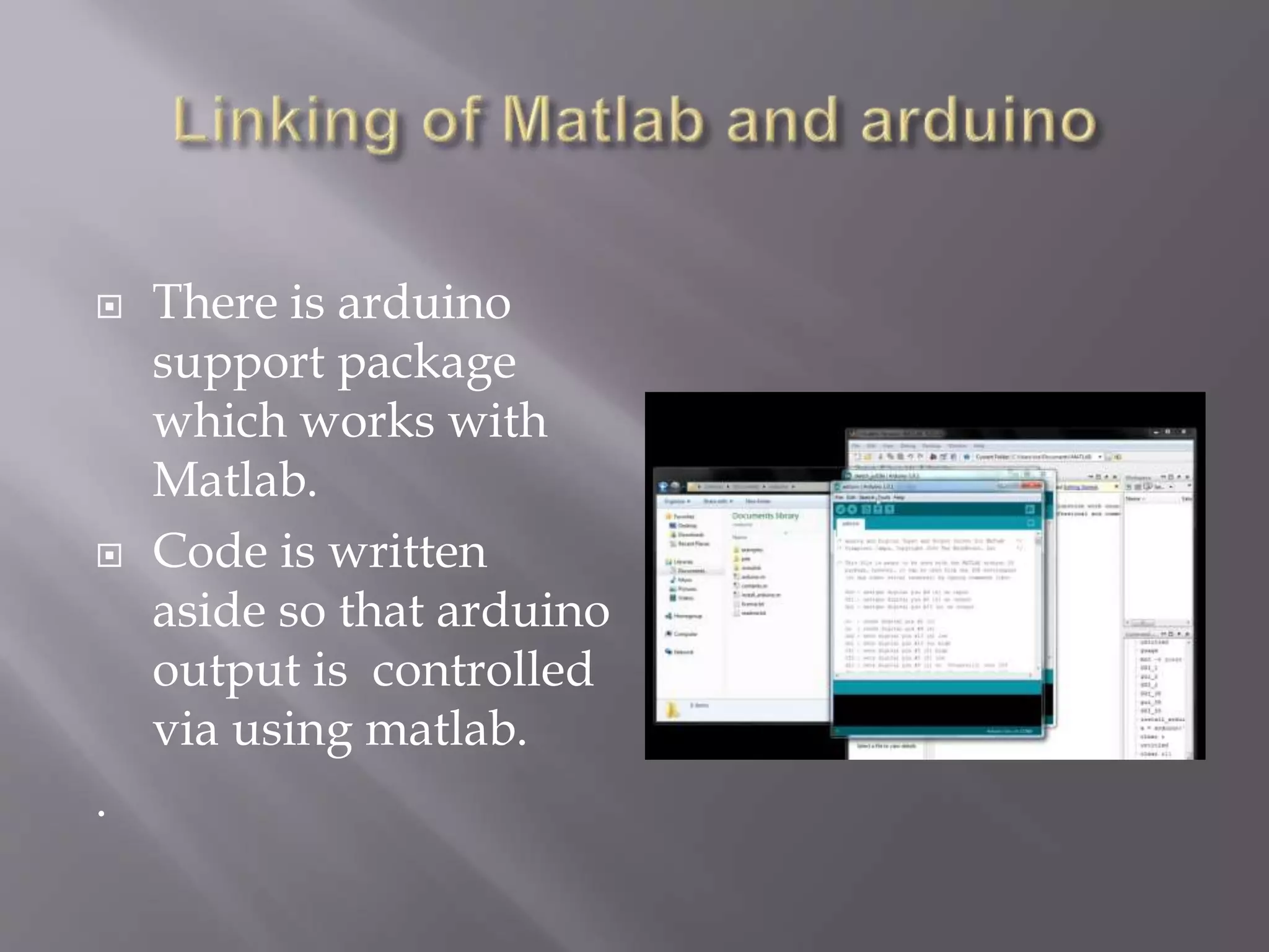
GUI BAESD DEVICE
CONTROLLER USING
MATLAB
 Objective
 Introduction to Project.
 Final look of project.
 What is new in this project?
 Future scope of project.
 Problem faced while doing project.
 Conclusion
In this project we created a graphical user interface
for controlling the output of Arduino in the Matlab
environment by synchronizing the Arduino output to
work according to pushbuttons created in Matlab Gui
tool .
In the following slides we will tell about the
graphical user interface and the Arduino and
serial communication of Arduino with laptop
and then synchronising of Matlab with Arduino.
5
 Graphical User Interface (GUI)
 MatLab provides Graphical User
Interface Development
Environment(GUIDE).
 A MatLab tool is used to create GUI’s
 GUI’s give the user a simplified
experience running a program.
6
 GUI should be consistent and easily
understood.
 Provide the user with the ability to use a
program without having to worry about
commands to run the actual program
 Possible components of a GUI
 Pushbuttons
 Sliders
 List boxes
 Menus….etc
Sample GUI
7
 Allows the user to drag and drop components
that he/she wants in the “layout” area of the
GUI
 All “guide” GUI’s start with an opening
function
 Callback is performed before user has access to GUI
 Saving automatically generates an .m file and
.fig file
 .fig contains the binary GUI layout and .m
contains the code that controls the GUI
 Arduino is an open-source physical
computing platform based on a simple i/o
board and a development environment that
implements the Processing / Wiring language.
Arduino can be used to develop stand-alone
interactive objects or can be connected to
software on your computer.
Analog
INPUTS
Digital IO
PWM(3, 5, 6, 9, 10, 11)
PWR IN USB
(to Computer)
SCLSDA
(I2C Bus)
POWER
5V / 3.3V / GND
RESET
 Also including an Integrated
Development Environment
(IDE) for programming.
 The language itself is based
in C .
 It is Open Source, both in terms of Hardware and
Software.
 It is cheap(1300रु), the hardware can be built from
components or a prefab board can be purchased
for approx 900रु.
 It can communicate with a computer via serial
connection over USB.
 It can be powered from USB or standalone DC
power.
 Plug it into the USB port and install the USB
drivers that come with the IDE.
 Open up the Arduino IDE and select the COM
port, usually COM1 or COM2 on a Windows
machine.
 Within the IDE, select the BAUD rate
(communication speed for serial connections)
 Set BAUD rate to 9600 on Windows.
 There is arduino
support package
which works with
Matlab.
 Code is written
aside so that arduino
output is controlled
via using matlab.
.
clear all;
global a;
a= arduino(‘com 1’);
a=pinMode(4,’output’);
a=pinMode(8,’output’);
 the name of push
buttons can be
changed by
changing string
name.
 In simple control of two leds , two pushbuttons
are being created in the gui tool then the codes
to be written to control the output of arduino
through pushbutton is given as
 For pushbutton 1
a=digitalwrite(4,0);
a=digitalwrite(8,1);
For pushbutton 2
a=digitalwrite(4,1);
a=digitalwrite(8,0);
 In this project we have demonstrated to link
the Matlab to control arduino output.
 Here only pushbuttons are to be used by the
user so no need to write the program again and
again once the decalartion has been done .
 This project doesn’t need exceptional coding
skills for arduino and matlab . A simple
knowledege to both can work .
Now this can be extended for home automation
using gsm module/bluetooth/android
application/ dtmf .
For eg if we use gsm module we can connect
with arduino via transmitter and receiver pins
then programming the gsm module using AT
commands and we can control the basic home
appliances just by dialing the phone no
associated with the gsm module .
1. Serial port communication : the arduino used
was not working because of the serial port was
not getting identified in the computer.
2. Gsm Module : while working with gsm
module the supplied voltage of 12V was given
instead of 9V which led to the damage of it
and it doesn’t catches the signal .Overall we
couldn’t extend our project because of this
anamaly.
Project is useful for the purpose of home
automation if extended further and is reliable
once installed . Our project dealt with simple
implementation of connecting matlab and
arduino to control the variables or equipments
connected on the output pins of it.

Final major presentation

  • 1.
  • 2.
     Objective  Introductionto Project.  Final look of project.  What is new in this project?  Future scope of project.  Problem faced while doing project.  Conclusion
  • 3.
    In this projectwe created a graphical user interface for controlling the output of Arduino in the Matlab environment by synchronizing the Arduino output to work according to pushbuttons created in Matlab Gui tool .
  • 4.
    In the followingslides we will tell about the graphical user interface and the Arduino and serial communication of Arduino with laptop and then synchronising of Matlab with Arduino.
  • 5.
    5  Graphical UserInterface (GUI)  MatLab provides Graphical User Interface Development Environment(GUIDE).  A MatLab tool is used to create GUI’s  GUI’s give the user a simplified experience running a program.
  • 6.
    6  GUI shouldbe consistent and easily understood.  Provide the user with the ability to use a program without having to worry about commands to run the actual program  Possible components of a GUI  Pushbuttons  Sliders  List boxes  Menus….etc Sample GUI
  • 7.
    7  Allows theuser to drag and drop components that he/she wants in the “layout” area of the GUI  All “guide” GUI’s start with an opening function  Callback is performed before user has access to GUI  Saving automatically generates an .m file and .fig file  .fig contains the binary GUI layout and .m contains the code that controls the GUI
  • 8.
     Arduino isan open-source physical computing platform based on a simple i/o board and a development environment that implements the Processing / Wiring language. Arduino can be used to develop stand-alone interactive objects or can be connected to software on your computer.
  • 9.
    Analog INPUTS Digital IO PWM(3, 5,6, 9, 10, 11) PWR IN USB (to Computer) SCLSDA (I2C Bus) POWER 5V / 3.3V / GND RESET
  • 10.
     Also includingan Integrated Development Environment (IDE) for programming.  The language itself is based in C .
  • 11.
     It isOpen Source, both in terms of Hardware and Software.  It is cheap(1300रु), the hardware can be built from components or a prefab board can be purchased for approx 900रु.  It can communicate with a computer via serial connection over USB.  It can be powered from USB or standalone DC power.
  • 12.
     Plug itinto the USB port and install the USB drivers that come with the IDE.  Open up the Arduino IDE and select the COM port, usually COM1 or COM2 on a Windows machine.  Within the IDE, select the BAUD rate (communication speed for serial connections)  Set BAUD rate to 9600 on Windows.
  • 13.
     There isarduino support package which works with Matlab.  Code is written aside so that arduino output is controlled via using matlab. .
  • 14.
    clear all; global a; a=arduino(‘com 1’); a=pinMode(4,’output’); a=pinMode(8,’output’);  the name of push buttons can be changed by changing string name.
  • 15.
     In simplecontrol of two leds , two pushbuttons are being created in the gui tool then the codes to be written to control the output of arduino through pushbutton is given as  For pushbutton 1 a=digitalwrite(4,0); a=digitalwrite(8,1); For pushbutton 2 a=digitalwrite(4,1); a=digitalwrite(8,0);
  • 17.
     In thisproject we have demonstrated to link the Matlab to control arduino output.  Here only pushbuttons are to be used by the user so no need to write the program again and again once the decalartion has been done .  This project doesn’t need exceptional coding skills for arduino and matlab . A simple knowledege to both can work .
  • 18.
    Now this canbe extended for home automation using gsm module/bluetooth/android application/ dtmf . For eg if we use gsm module we can connect with arduino via transmitter and receiver pins then programming the gsm module using AT commands and we can control the basic home appliances just by dialing the phone no associated with the gsm module .
  • 19.
    1. Serial portcommunication : the arduino used was not working because of the serial port was not getting identified in the computer. 2. Gsm Module : while working with gsm module the supplied voltage of 12V was given instead of 9V which led to the damage of it and it doesn’t catches the signal .Overall we couldn’t extend our project because of this anamaly.
  • 20.
    Project is usefulfor the purpose of home automation if extended further and is reliable once installed . Our project dealt with simple implementation of connecting matlab and arduino to control the variables or equipments connected on the output pins of it.