The document describes the development of a wireless neural interface platform for epidural spinal cord implants in rats. Key components include:
1) An Android tablet app for controlling stimulation parameters wirelessly.
2) A microcontroller unit that modulates and transmits power and data via inductive coils to an implant.
3) An implant that decodes signals and initiates spinal cord stimulation.
Independent circuitry for each component has been developed and the overall system aims to provide more versatile and customizable spinal cord stimulation than existing options.
![IOP Publishing Journal of Neural
Engineering
A Wireless Neural Interface Platform for
Epidural Spinal Cord Implants in Rats
Capstone Group E
Team members: Isaac Cassar, Trevor Davis, Ben Johnson, Kanav Saraf, Cory Schroeder,
Connor Sullivan
ABSTRACT
Objective. Spinal cord injuries result in damage of the spinal column, with the most severe cases
leading to paralysis. Treatments, such as epidural spinal cord stimulation, aim at restoring the
patients’ ability to regain motor and sexual control of their body. In this paper, we discuss the
development of a system for use in in vivo epidural spinal cord stimulation experiments that
provides wireless control over a spinal cord implant designed previously in Dr. Wentai Liu’s lab.
Our proposed system marks the next step in the miniaturization and mobilization of epidural spinal
cord stimulation therapy. Approach. Our system consists of: an android application, a WiFi
module, a microcontroller unit (MCU), a Differential Phase-Shift Keying (DPSK) circuit and
inductive power and data coils. Each of the components have been developed independently and
are now ready to be assembled into a composite system. Main result. Independent benchtop
circuitry has been developed that will be incorporated into the final completed system.
Significance. The implant that we have created this wireless interface for is the first implant that
allows for simultaneous stimulation and recording of spinal cord signals. In the future, our wireless
spinal cord implant interface platform can be expanded to include a bidirectional flow of data both
to and from the implant.
INTRODUCTION
A spinal cord injury (SCI) describes any injury or damage to the spinal column, with the most
severe SCI leading to paralysis [1]. Currently there are over 1,275,000 people living with SCI in
the United States, and an additional 12,500 new cases occur every year [2]. There are no
reparative treatments for SCI; instead current standard medical treatment is focused on
maintaining patient quality of life and reducing secondary complications from SCI such as blood
clots, faulty bladder control, and poor bowel management.
A novel technique being pioneered to restore function to SCI paralyzed patients is epidural Spinal
Cord Stimulation (SCS), where an electrode array is implanted on the spinal column that sends
pulsed electrical signals along the neurons [3, 4]. SCS was initially targeted at alleviating patient
pain. This was found to be successful as pain reduction was demonstrated across more than 61
peer-reviewed studies [5, 6]. In recent years SCS has also been shown to restore locomotion in
some patients. The first study that was able to demonstrate rhythmic stepping in paralyzed rats
during treatment with SCS was performed in 2005 in our collaborator Dr. Reggie Edgerton’s
laboratory at UCLA [7]. In the years since, SCS treatment on human patients has allowed patients
to regain full weight-bearing standing and initiate supine leg movements [8-9].](https://image.slidesharecdn.com/be122dbb-e6a9-4e39-8bee-834843f24029-161117010510/85/Final-Draft-of-Research-Paper-1-1-320.jpg)
![IOP Publishing Journal of Neural
Engineering
A Wireless Neural Interface Platform for
Epidural Spinal Cord Implants in Rats
Capstone Group E
Team members: Isaac Cassar, Trevor Davis, Ben Johnson, Kanav Saraf, Cory Schroeder,
Connor Sullivan
ABSTRACT
Objective. Spinal cord injuries result in damage of the spinal column, with the most severe cases
leading to paralysis. Treatments, such as epidural spinal cord stimulation, aim at restoring the
patients’ ability to regain motor and sexual control of their body. In this paper, we discuss the
development of a system for use in in vivo epidural spinal cord stimulation experiments that
provides wireless control over a spinal cord implant designed previously in Dr. Wentai Liu’s lab.
Our proposed system marks the next step in the miniaturization and mobilization of epidural spinal
cord stimulation therapy. Approach. Our system consists of: an android application, a WiFi
module, a microcontroller unit (MCU), a Differential Phase-Shift Keying (DPSK) circuit and
inductive power and data coils. Each of the components have been developed independently and
are now ready to be assembled into a composite system. Main result. Independent benchtop
circuitry has been developed that will be incorporated into the final completed system.
Significance. The implant that we have created this wireless interface for is the first implant that
allows for simultaneous stimulation and recording of spinal cord signals. In the future, our wireless
spinal cord implant interface platform can be expanded to include a bidirectional flow of data both
to and from the implant.
INTRODUCTION
A spinal cord injury (SCI) describes any injury or damage to the spinal column, with the most
severe SCI leading to paralysis [1]. Currently there are over 1,275,000 people living with SCI in
the United States, and an additional 12,500 new cases occur every year [2]. There are no
reparative treatments for SCI; instead current standard medical treatment is focused on
maintaining patient quality of life and reducing secondary complications from SCI such as blood
clots, faulty bladder control, and poor bowel management.
A novel technique being pioneered to restore function to SCI paralyzed patients is epidural Spinal
Cord Stimulation (SCS), where an electrode array is implanted on the spinal column that sends
pulsed electrical signals along the neurons [3, 4]. SCS was initially targeted at alleviating patient
pain. This was found to be successful as pain reduction was demonstrated across more than 61
peer-reviewed studies [5, 6]. In recent years SCS has also been shown to restore locomotion in
some patients. The first study that was able to demonstrate rhythmic stepping in paralyzed rats
during treatment with SCS was performed in 2005 in our collaborator Dr. Reggie Edgerton’s
laboratory at UCLA [7]. In the years since, SCS treatment on human patients has allowed patients
to regain full weight-bearing standing and initiate supine leg movements [8-9].](https://image.slidesharecdn.com/be122dbb-e6a9-4e39-8bee-834843f24029-161117010510/75/Final-Draft-of-Research-Paper-1-1-2048.jpg)
![Although these initial results have been promising, current SCS treatment for the recovery of
locomotion is not without its limitations. Researchers using current systems run into complications
because they are not using them for their designed purpose, resulting in the FDA setting limits on
tests performed on human patients per week [8-9]. In addition, current neurostimulators are not
versatile enough to allow customization across different patients. These devices also lack the
ability to record signals from the spinal column, which is helpful in patient diagnosis and analysis
of device function. To provide versatility for patient treatment, a device should be capable of
controlling multiple electrodes with different parameters including: anodic/cathodic current
intensity, anodic/cathodic pulse width, start delays, interphase delays, waveform polarity, pulse
train size, and pulse train frequency.
In this paper, we detail the process of creating a neural interface platform that is capable of
incorporating new functionality specific to movement restoration. We discuss the creation and
debugging of each individual component of this platform. When assembled, the system powers
the implant wirelessly and enables wireless control with a user-friendly Graphical User Interface
(GUI). This GUI is in the form of an Android application and can control a variety of stimulation
parameters along with allowing for the incorporation of bidirectional data flow both to and from
the implant.
Our proposed system, which we call the uWalk Again, can be broken down into the three parts
seen in Figure 1. Part A consists of a user-friendly Android tablet application that controls (part B)
a Microcontroller Unit (MCU) placed in a jacket worn by the rat. The MCU modulates and transmits
power and data through the Class E circuit to the inductive coils housed in the jacket to inductive
coils implanted within the rat. The implant, part C, decodes these signals and initiates spinal cord
stimulation. The specific design parameters used when developing each individual component
are described in the paragraphs below.
Figure 1: A systematic overview of the three components of the uWalk Again. (A) shows the tablet in which
the researcher inputs testing parameters. (B) Shows the printed circuit board (PCB) that would be housed
on the jacket that contains the WiFi module, MCU, Battery, and power/data coils. (C) Shows the implant
that is placed right underneath the internal power and data coils.](https://image.slidesharecdn.com/be122dbb-e6a9-4e39-8bee-834843f24029-161117010510/85/Final-Draft-of-Research-Paper-1-2-320.jpg)
![METHODS
GUI Programming
One of the first tasks to address in overcoming the shortcomings of previous systems is to create
a versatile and user-friendly control interface. The GUI was designed for the Samsung Nexus 10
tablet running Android Lollipop 5.0.1. The programming was done using XML (Extensible Markup
Language) and Java on the Android Studio 1.0 software development kit (SDK) based on APK
21. The tablet application has been designed keeping in mind the Material Design guidelines put
forward by Google for Android Lollipop 5.0.1 in 2014. These guidelines address the appearance
of any application in order to make the layout intuitive for the user. Lastly, the WiFi transmission
java code is loosely based on a C-sharp code previously created in the lab of Dr. Wentai Liu [10].
This interface was combined with the WiFi transmission code on the program and the app was
downloaded on the tablet to serve as the master controller of the entire system.
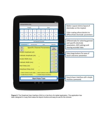
The ergonomics of our application interface have been addressed in four main ways. Firstly, the
tablet application uses large button sizes and styles to avoid accidental-touches by the user.
Secondly, the selectable button layout for the electrode array mirrors the actual position of
electrodes on the implant. This eliminates the need for the user to memorize electrode labels, and
allows them to intuitively stimulate electrodes simply based on their positions in the button layout.
Thirdly, each group of electrodes is color coded on selection. Groups of electrodes with the same
parameters are assigned the same color, while different groups of electrodes have different colors
in order to provide a visual confirmation to the user that their electrode configurations have been
properly set up prior to stimulation. Finally, the application also takes advantage of tabbed layouts
to allow for the controls to be comfortably spaced out, yet still include all the necessary functions
on the same app-screen. These four stylistic choices are highlighted in Figure 2. Additionally, we
also compare this interface with the user-interface for a neurostimulator platform created by
Medtronic called N’Vision [11]. The usability of this interface is demonstrated later in the results.](https://image.slidesharecdn.com/be122dbb-e6a9-4e39-8bee-834843f24029-161117010510/85/Final-Draft-of-Research-Paper-1-3-320.jpg)
![MCU Programming
A key intermediate between data representation on the tablet and the data acquisition from the
implant is the MCU. As such, we acquired an MCU (Microchip PIC24HJ128GP502) and coded it
in C language, using MPLAB X IDE as the programming software. Code was uploaded from
MPLAB to the MCU using a small printed circuit board (PCB) (Microchip Microstick II) as the
programming tool; this PCB connected to the computer through USB and has the capability to
connect to a breadboard, allowing for easy programming and testing of the MCU. A WiFi module
(Microchip RN-171 WiFly) was purchased in order to establish data communication between the
tablet and the MCU; the RN-171 runs at 2.4 GHz under IEEE 802.11 wireless local area network
specifications, which allows for local communication between devices. The RN-171
communicates using UART (Universal Asynchronous Receiver/Transmitter) technology, which
transmits information via packets of eight bits (one byte) for serial communication between a
transmitter and a receiver. Received data is outputted from the module serially. The WiFi module
facilitates the transmission of encoded binary data carrying information on the stimulation
parameters of the electrodes from the tablet to the MCU. An Arduino Yun was used to simulate
test data transmission between the WiFi module and MCU without programming the WiFi module
and establishing connection between the tablet and module. The Yun was connected to the MCU
via a breadboard, and sample binary data was sent from the Yun to the MCU using the same
UART format that the WiFi module follows. This data was read from the UART register within the
MCU and outputted at a frequency of 2 MHz to the Differential Phase-Shift Keying (DPSK) circuit.
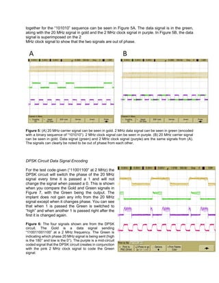
In addition to this 2 MHz data signal, a 20 MHz frequency signal and a 2 MHz frequency clock
signal (out of phase with the data signal) were programmed and outputted by the MCU to the
DPSK circuit for use in digital modulation of a carrier wave to encode data.
Communication and Transmission of Data and Power to Implant
The MCU receives the full data in a 19-bit data binary form and will output that data to the implant.
This is done through a DPSK circuit. The data in 19-bit format is in simple binary code. In order
to communicate the ones and zeros to the implant, the DPSK circuit uses two different phase 20
MHz (one at 0° phase and one at 180°) signals to induce phase changes in the data coils. The
MCU is connected to the DPSK circuit and provides the circuit with the 20 MHz carrier signals, a
2 MHz clock signal and a 2 MHz data signal. The DPSK circuit is connected to the data coil Class
E circuit and providing it with a 20 MHz signal.
The data is transmitted by switching between the two 20 MHz signals. Every time a 1 is passed
to the DPSK circuit from the MCU, the DPSK circuit is set up to switch the phase of the signal,
which the implant then records as a 1. Anytime a 0 is sent from the MCU the DPSK circuit does
not change the phase and the implant recognizes the same signal and that there was not a change
during that time cycle and records a 0.
Power and Data Coil Construction
The designs of the power and data coils were carried out based on constraints such as voltages,
currents, and frequencies necessary for the implant, the size of the inner coils, and the spacing
between the inner and outer coils. The power coils were designed to maximize power transfer
efficiency, which required a high quality factor in the coils, and the data coils were designed to
maximize their bandwidth, which required a low quality factor. Based off of these constraints, the
coils were designed using the procedures outlined in [12-14] with their calculated parameters
presented in Table 1.](https://image.slidesharecdn.com/be122dbb-e6a9-4e39-8bee-834843f24029-161117010510/85/Final-Draft-of-Research-Paper-1-5-320.jpg)
![Table 1. Design Parameters for Power and Data Coils
Parameter Power Coil Data Coil
Induced Voltage 12 V 6 V
Induced Current 10 mA 4.75 mA
Frequency 2 MHz 20 MHz
Inner Coil (IC) Diameter 5 mm 5 mm
Outer Coil (OC) Diameter 30.4 mm 10 mm
IC Width 1.6 mm 1.6 mm
OC Width 2 mm 2 mm
Coil Separation 1.5 cm 1.5 cm
IC Number of Turns 15 10
OC Number of Turns 10 10
IC Inductance 1 μH 1 μH
OC Inductance 5 μH 1 μH
IC Quality Factor >75 5 – 15
OC Quality Factor >75 5 – 15
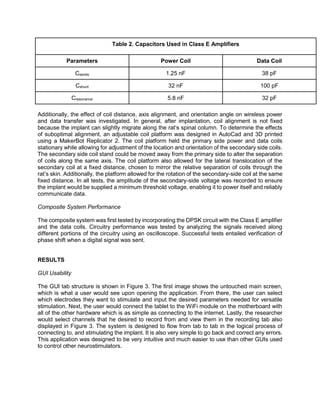
After determining the appropriate design parameters, cylindrical bobbins were printed on a
Makerbot 3D printer to provide the specified diameter for the coils. To assemble the power coils,
Litz wire was wrapped around the bobbins according to the calculated number of turns. The data
coils used 36 gauge copper wire wrapped around the bobbin. To secure coils for removal from
the bobbin, a Silicone Elastomer Kit (Dow Corning) was used to solidify a thin layer of silicone
between the coil turns. Coils were then removed from the bobbin and ready for further testing.
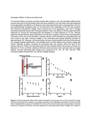
Orientation Effects of Power and Data Coils
Class E amplifier circuits were designed for both the power and data coils according to the
procedure outlined in [15]. After connecting the amplifiers to the coils, the ability of the coil
containing circuit to transfer power or data signal wirelessly to the implant-side circuitry was
analyzed by measuring the voltage output across both the primary-side and secondary-side
inductors with an oscilloscope. Class E circuit capacitance values were tuned with the addition or
removal of further capacitors until an optimum voltage amplitude was reached, shown in Table 2.](https://image.slidesharecdn.com/be122dbb-e6a9-4e39-8bee-834843f24029-161117010510/85/Final-Draft-of-Research-Paper-1-6-320.jpg)
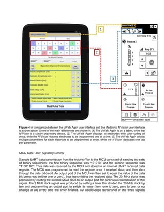
![Figure 3: (1) The home screen of the uWalk Again GUI that clinicians will interface with first. (2) The tab
where specific electrode parameters can be set for a variety of electrode groupings. Electrodes with
different parameters are shown with different colors. (3) Tab view where researchers will connect to the
WiFi module on the uWalk Again. (4) The tab where recorded data can be displayed.
In order to demonstrate the usefulness of this application, its interface is compared to that of
Medtronic’s N’Vision neurostimulator system [11] with the differences highlighted in Figure 4. This
programming device developed by Medtronic has many limitations. Firstly, Medtronic’s device is
only available through purchase from that company causing users decreased accessibility to the
device compared to the uWalk Again system which is available as an Android application on any
Android device. Secondly, the interface created by Medtronic is methodical, slow and prone to
accidental error. Aside from their GUI being difficult to understand at first glance, the main
limitation lies in the fact that clinicians can only change one parameter for one electrode at a time.
For example, there are separate tabs for the amplitude, pulse width and frequency for each
individual electrode causing programming to be slow. This keeps clinicians from being able to
view the entire electrode configuration at once and correcting input errors. Lastly, our system
allows multiple electrodes to be programmed at once and displays multiple parameters to allow
for programming to be faster. Our system also shows color coded buttons to serve as a visual
confirmation that specific electrodes don’t accidentally differ by one parameter.](https://image.slidesharecdn.com/be122dbb-e6a9-4e39-8bee-834843f24029-161117010510/85/Final-Draft-of-Research-Paper-1-8-320.jpg)
![Figure 9: The Gold signal represents the output 20 MHz signal from the DPSK circuit to the coils. The
Green is the same signal from Figure 6 and is the DPSK signal to change the phase of the 20 MHz signal.
The Purple and Pink signals on the bottom are the coil signals. With this information we can see correct
data transmission and a strong transmission connection between the data coils.
DISCUSSION
The uWalk Again design advances the field of epidural spinal cord stimulation research. The
layout of the GUI has been shown to be logical and intuitive in its operation. It is also much more
versatile and ergonomic compared to other programming devices on the market today. As such,
the uWalk Again will allow for and promote an increase in the volume of epidural spinal cord
stimulation research being performed simply as a result of its increase in usability.
Figures 8 and 9 show the successful transmission of data from the MCU to the implant wirelessly.
This is a key step in making spinal cord injury treatment plausible. This capability minimizes the
amount of hardware implanted into the patient while still including those components necessary
to accomplish the required versatility of stimulation. Reducing the amount of implanted hardware
promotes the longevity of the system. Furthermore, because of wireless communication, most of
the system components lie outside the body - which makes it easy to add or remove different
hardware components in the future to allow for system simplification or enhancement. Another
benefit of this external motherboard is seen in the ability to do simple tasks like change or
recharge the systems batteries. We have further reason to believe this system to be successful
because similar systems such as retinal prosthetics have also capitalized on the benefits of
wireless communication to control the implant from outside the body and demonstrated effective
treatment or therapy [16, 17].
In addition to wireless communication, the results from our coil dislocation studies are indicative
of successful future function of power and data transfer using the uWalk Again. When considering
power transfer, the implant-side circuitry must be supplied enough power to control all circuit](https://image.slidesharecdn.com/be122dbb-e6a9-4e39-8bee-834843f24029-161117010510/85/Final-Draft-of-Research-Paper-1-13-320.jpg)
![elements and to stimulate the spinal column with a sufficient current when commanded to do so.
From the design of the implant created by the Liu lab, this entails inducing a DC voltage of at least
10 V. Our data suggests that a secondary-side voltage of 10 V is reached at a distance of 10 mm.
Rat’s skin can range in depth from 6 mm to 12 mm, and as such, the fact that this voltage is
maintained while at a distance mirroring that found in future application suggests that power will
be adequately transferred through that depth. Furthermore, analysis of the distance-off-axis graph
suggests that this 10 V induced DC voltage will be maintained regardless of whether the coil axes
are centered. When moved to both the left and the right of center, induced voltage remained
around 10 V until the secondary-side coil began to overlap with the edge of the primary-side coil.
Thus, after implantation when the coil migrates away from its original implantation position, it
should still be capable of providing sufficient voltage to the implant given that the smaller 5 mm
diameter secondary-side coil remains within the larger 30.4 mm diameter primary side coil. Angle
effects do seem to provide a significant obstacle to sufficient power transfer to the implant side.
After rotating the axis only 30°, induced voltage had already dropped such that it was only 70%
of its value when the axes were aligned. As such, when implanting into rats, special consideration
needs to be given to ensuring proper angle alignment. The coil should be aligned such that the
normal vector to its area runs parallel with the normal vector from the rat’s skin. One possible way
to ensure this alignment is by placing the implant so that it rests along the rat’s rib cage. Using
this alignment, the secondary-side power coil would rest upon a hard surface that would prevent
axis rotation, and hence optimize our power transfer efficiency.
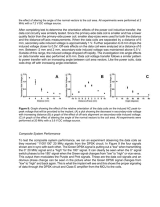
Successful data transfer alludes to future success of the composite uWalk Again system in vivo.
To adequately transfer data signals, the induced voltage must be significant enough to be greater
than any noise picked up by the secondary-side data coil. Experimentally, the signal must be
above the threshold noise limit of 100 mV. As long as the secondary-side induced voltage
surpasses 100 mV, data signals can be decoded. The induced voltage is greater than 200 mV
over the range from 4 mm separation to 10 mm separation, allowing the potential for data to be
transferred over that range. Next, the data coils axis alignment was shifted from 10 mm left of the
coil to 10 mm right of the coil. Induced voltage surpassed the threshold voltage from -6 mm to 6
mm, indicating the potential for data transfer over this range. Unlike the power coils, the data coils
do not plateau at a fixed voltage during this experiment. This makes sense intuitively as the data
coils were designed to have a low quality factor and high bandwidth, and as such are more prone
to have inhomogeneities in the induced magnetic field and the subsequent induced current within
the secondary-side coil. Finally, the data coils shared a similarly patterned decrease in voltage
with increasing angle as the power coils. Threshold voltage was surpassed for the data coils,
provided the secondary-side coil was not rotated greater than 45°. As such, the data coils would
benefit from the same surgical alignment necessitated by the power coils. This will not hinder
device function as both the power and data coils are intended to be used coaxially. This approach
has already been applied in the case of retinal prosthetics [16, 17].
CONCLUSION
The uWalk again is designed as a neural engineering platform that makes it easier for researchers
to perform effective and efficient experiments in spinal cord injury therapy on rats. We have
finished the design of a GUI that is superior in functionality to those that are currently on the
market. Secondly, we have designed power and data coils capable of providing the required
voltage to communicate with and power the implant. Lastly, we have assembled a composite
system that modulates the phase of a 20 MHz signal to effectively transmit data.
In our future work, our first goal is to create a printed circuit board (PCB) of the system that
incorporates the entire composite circuitry into a single PCB design. Next, we aim to assemble](https://image.slidesharecdn.com/be122dbb-e6a9-4e39-8bee-834843f24029-161117010510/85/Final-Draft-of-Research-Paper-1-14-320.jpg)
![the final system into a jacket that will carry this PCB. Finally, we aim to use this compiled system
for in vivo testing, where paralyzed rats will undergo epidural spinal cord stimulation controlled by
the uWalk Again. In this testing researchers will be able to use the implant for stimulation therapy
and collect recorded data from the rats wirelessly. The aim of this system is to make it easy for
the researcher to handle more than a few implants at the same time, and hence increase the
efficiency of spinal cord research. If conducting research is easier, there will be larger amounts of
data for the spinal cord injury research database. An ever expanding database can bring us one
step closer to finding out a cure for lifelong paralysis.
We anticipate the development of a more comprehensive program for the MCU to incorporate a
“closed loop” system so no actual adjustments are needed from a user would allow a more
realistic use of our system in the real world. Our work here gives a strong basis for all these
advancements and allows researchers to take modern technology further than has been seen
before.
REFERENCES
[1] Kirshblum SC, Burns SP, Waring W, “International standards for neurological classification of spinal cord injury,”
J Spin Cord Med, vol. 34, 2011, 535-546.
[2] National Spinal Cord Injury Statistical Center, Facts and Figures At a Glance. Birmingham, AL: University of
Alabama at Birmingham, March 2013.
[3] Popovic DB, “Advances in functional electrical stimulation,” J Electromyography and Kinesiology, vol. 24, 2014,
795-802.
[4] Kumar K, Toth C, Laing P, “Epidural spinal cord stimulation for the treatment of chronic pain – some predictors of
success,” Surg Neurol, vol. 50, 1998, 110-121.
[5] Cameron T, “Safety and efficacy of spinal cord stimulation for the treatment of chronic pain: a 20-year literature
review,” J Neurosurg, vol. 100, 2004, 254-267.
[6] RestoreAdvanced Surescan MRI Neurostimulator. Medtronic, Jan 2014. Web. 14 Dec 2014.
[7] Fong AJ, Roy RR, Burdick J, Edgerton VR, “Recovery of control of posture and locomotion after a spinal cord
injury: solutions staring us in the face,” Prog Brain Res, vol. 175, 2009, 393-418.
[8] Harkema S, “Effect of epidural stimulation of the lumbosacral spinal cord on voluntary movement, standing, and
assisted stepping after motor complete paraplegia: a case study,” Lancet, vol. 500, 2011, 1938-1947.
[9] Sayenko DG, Angeli CA, Harkema SJ, Edgerton VR, Gerasimenko YP, “Neuromodulation of evoked muscle
potentials induced by epidural spinal cord stimulation in paralyzed individuals,” J Neurophysiol, vol. 111(5), 2014,
1088–1099.
[10] Kuanfu, Chen. (2011). Retinal Implant: System Analysis and Design With Customized Retinal ICS. Unpublished
doctoral dissertation, University of California, Santa Cruz
[11] Medtronic (2008). Interstim Therapy: N’Vision Model 8840 Clinician Programmer and Model 8870 Application
Card. Minneapolis; Medtronic Inc.
[12] Wang G, Liu W, Sivaprakasam M, “Design and analysis of an adaptive transcutaneous power telemetry for
biomedical implants," IEEE Transactions on Circuits and Systems, vol. 52, 2005, 2109-2117.
[13] Ko WH, Sheau PL, and Fung CD, “Design of radio-frequency powered coils for implant instruments,” Medical &
Biological Engineering & Computing, vol. 25, 1977, 634-640.
[14] Terman, FE. Radio Engineers' Handbook. New York: McGraw-Hill Book, 1943.
[15] Kendir GA, “An optimal design methodology for inductive power link with class-E amplifier,” IEEE Transactions
on Circuits and Systems, vol. 52, 2005, 857-866.
[16]W. Liu and M.S. Humayun, “Retinal prosthesis,” in Proc. IEEE Int. Solid-State Circuits Conf., San Francisco, CA,
2004, pp. 218–219
[17]Lo YK, Chen K, Gad P, and Liu W, “A fully-integrated high-compliance voltage SoC for epi-retinal and neural
prostheses," IEEE Transactions on Biomedical Circuits and Systems, vol. 7, 2014, 761-772.](https://image.slidesharecdn.com/be122dbb-e6a9-4e39-8bee-834843f24029-161117010510/85/Final-Draft-of-Research-Paper-1-15-320.jpg)


![pavippt [654168]](https://cdn.slidesharecdn.com/ss_thumbnails/a3523e7d-c1bc-4cdd-9958-aeae5acc0f82-161015072919-thumbnail.jpg?width=640&height=640&fit=bounds)
