Downloaded 170 times


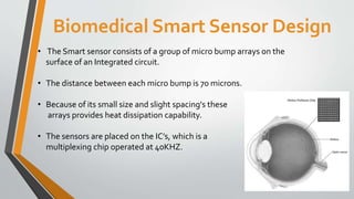


This document describes the design of a biomedical smart sensor to help restore vision in visually impaired individuals. It discusses various methods used, including retinal and cortical implants. The smart sensor design involves an array of microsensors placed on an integrated circuit, which can transmit and receive data wirelessly. Issues include high power consumption and maintaining proper alignment of internal and external coils used for power transfer and communication. The goal of the smart sensor is to improve quality of life by enhancing artificial vision capabilities.


![Artificial retina [shweta]](https://cdn.slidesharecdn.com/ss_thumbnails/artificialretinashweta-161013192718-thumbnail.jpg?width=640&height=640&fit=bounds)


