Download to read offline
![Surya Narayan Pradhan et al Int. Journal of Engineering Research and Applications www.ijera.com
ISSN : 2248-9622, Vol. 4, Issue 5( Version 1), May 2014, pp.149-153
www.ijera.com 149 | P a g e
Design & Implementation of a Low Cost Based Wireless HCI
System for Disabled Persons Using ARM7
Surya Narayan Pradhan*, Debidatta Acharya**, Soumyashree Mongaraj***
*M.Tech Student (Department of Electronics & Communication, KIIT University, Bhubaneswar, INDIA)
**M.Tech Student (Department of Electronics & Communication, KIIT University, Bhubaneswar, INDIA)
*** Assistant Professor (Department of Electronics & Communication, KIIT University, Bhubaneswar, INDIA)
Abstract
This paper focuses on design & development of a portable wireless Human Computer Interface (HCI) system to
create a robust hands free interface for disabled peoples or peoples having upper limb motor paralysis. Early
techniques mainly considered image processing, gaze tracking and cameras to synthesis the device. We propose
a new mouse as an input device for a computer whose operation is based on measurement of rotations of the
user‘s head and detection of eye blinks. A tilt sensor(3-axis accelerometer) is used to detect both lateral and
vertical head movements to navigate the mouse cursor position placed on a helmet .The IR based eye blink
sensor is placed on a spec used to detect eye blink and in turns do clicking operation. The signals are sent to the
micro-controller (ARM7 LPC2148) for processing & do required operations. The wireless technology includes
Zigbee module used to sends signals to the computer in use. A C# based program is developed for the mouse
control operations & provides a flexible method for the disabled people to improve both personal & professional
life quality.
Keywords—Accelerometer, ARM7 Lpc2148, Eye blink sensor, HCI, Zigbee
I. INTRODUCTION
In the era of science & technology
computers are an integral part of life that makes
human life more comfortable. Human Computer
Interface (HCI) is a technology used to incorporate
the correlation between human and Computer. HCI
device which use information taken from the head
area offer interaction methods that are more
Convenience, spontaneous & intuitive compared to
the traditional input devices like keyboard, or mouse.
One of the most benefitted target groups is
physically disabled people having spinal cord
problem, motor paralysis & who cannot use their
hands in the interaction. Additionally as the number
of people with disabilities is increasing drastically
several researches has been going on for effective
Human computer interaction.
According to the users‘ ability, systems like
speech recognition, brain-computer interfaces (BCI)
and infrared head-operated joysticks etc. may be
involved for this purpose. However patients with
several disabilities may not able to speak and eye
muscles are the only muscle they can control. Some
prominent Eye-movement detection interfaces may
be based on videooculography (VOG), image
analysis [1], infraredoculography (IORG)[2]
,electrooculography (EOG)[3] [4] and
electromyography(EMG)[5]. Furthermore, this type
of interface is not be limited to critically disabled
Peoples and could be applicable to any one with
enough eye-movement control.
EOG is a widely and successfully
implemented technique that has proven reliable
human–computer interfaces (HCI) where electrode-
based device is designed to enable people with
special needs to control a computer with their eyes
but it leads to an uncomfortable way of act as several
electrodes are placed on face near eye area.
Gaze tracking recommended as an
alternative to traditional computer pointing
mechanisms. However, the precision or accuracy
limitations of gaze estimation algorithms and the
fatigue imposed on users when overloading the
visual perceptual channel with a motor control task
have prevented the widespread adoption of gaze as a
pointing modality. The prototype system combines
head-mounted, video-based gaze tracking with
capacitive facial movement detection that enable
multimodal interaction by gaze pointing and making
selections with facial gestures [6]
Brain Computer Interfaces (BCIs)[7]
measure brain signals of brain activity intentionally
and unintentionally induced by the user, and thus
provide a promising communication channel that
does not depend on the brain‘s normal output
pathway consisting of peripheral nerves and muscles.
Present-day Brain Computer Interfaces determine the
intent of the user from a variety of different
electrophysiological signals. They translate these
RESEARCH ARTICLE OPEN ACCESS](https://image.slidesharecdn.com/z4501149153-140716025200-phpapp02/85/Z4501149153-1-320.jpg)
![Surya Narayan Pradhan et al Int. Journal of Engineering Research and Applications www.ijera.com
ISSN : 2248-9622, Vol. 4, Issue 5( Version 1), May 2014, pp.149-153
www.ijera.com 149 | P a g e
Design & Implementation of a Low Cost Based Wireless HCI
System for Disabled Persons Using ARM7
Surya Narayan Pradhan*, Debidatta Acharya**, Soumyashree Mongaraj***
*M.Tech Student (Department of Electronics & Communication, KIIT University, Bhubaneswar, INDIA)
**M.Tech Student (Department of Electronics & Communication, KIIT University, Bhubaneswar, INDIA)
*** Assistant Professor (Department of Electronics & Communication, KIIT University, Bhubaneswar, INDIA)
Abstract
This paper focuses on design & development of a portable wireless Human Computer Interface (HCI) system to
create a robust hands free interface for disabled peoples or peoples having upper limb motor paralysis. Early
techniques mainly considered image processing, gaze tracking and cameras to synthesis the device. We propose
a new mouse as an input device for a computer whose operation is based on measurement of rotations of the
user‘s head and detection of eye blinks. A tilt sensor(3-axis accelerometer) is used to detect both lateral and
vertical head movements to navigate the mouse cursor position placed on a helmet .The IR based eye blink
sensor is placed on a spec used to detect eye blink and in turns do clicking operation. The signals are sent to the
micro-controller (ARM7 LPC2148) for processing & do required operations. The wireless technology includes
Zigbee module used to sends signals to the computer in use. A C# based program is developed for the mouse
control operations & provides a flexible method for the disabled people to improve both personal & professional
life quality.
Keywords—Accelerometer, ARM7 Lpc2148, Eye blink sensor, HCI, Zigbee
I. INTRODUCTION
In the era of science & technology
computers are an integral part of life that makes
human life more comfortable. Human Computer
Interface (HCI) is a technology used to incorporate
the correlation between human and Computer. HCI
device which use information taken from the head
area offer interaction methods that are more
Convenience, spontaneous & intuitive compared to
the traditional input devices like keyboard, or mouse.
One of the most benefitted target groups is
physically disabled people having spinal cord
problem, motor paralysis & who cannot use their
hands in the interaction. Additionally as the number
of people with disabilities is increasing drastically
several researches has been going on for effective
Human computer interaction.
According to the users‘ ability, systems like
speech recognition, brain-computer interfaces (BCI)
and infrared head-operated joysticks etc. may be
involved for this purpose. However patients with
several disabilities may not able to speak and eye
muscles are the only muscle they can control. Some
prominent Eye-movement detection interfaces may
be based on videooculography (VOG), image
analysis [1], infraredoculography (IORG)[2]
,electrooculography (EOG)[3] [4] and
electromyography(EMG)[5]. Furthermore, this type
of interface is not be limited to critically disabled
Peoples and could be applicable to any one with
enough eye-movement control.
EOG is a widely and successfully
implemented technique that has proven reliable
human–computer interfaces (HCI) where electrode-
based device is designed to enable people with
special needs to control a computer with their eyes
but it leads to an uncomfortable way of act as several
electrodes are placed on face near eye area.
Gaze tracking recommended as an
alternative to traditional computer pointing
mechanisms. However, the precision or accuracy
limitations of gaze estimation algorithms and the
fatigue imposed on users when overloading the
visual perceptual channel with a motor control task
have prevented the widespread adoption of gaze as a
pointing modality. The prototype system combines
head-mounted, video-based gaze tracking with
capacitive facial movement detection that enable
multimodal interaction by gaze pointing and making
selections with facial gestures [6]
Brain Computer Interfaces (BCIs)[7]
measure brain signals of brain activity intentionally
and unintentionally induced by the user, and thus
provide a promising communication channel that
does not depend on the brain‘s normal output
pathway consisting of peripheral nerves and muscles.
Present-day Brain Computer Interfaces determine the
intent of the user from a variety of different
electrophysiological signals. They translate these
RESEARCH ARTICLE OPEN ACCESS](https://image.slidesharecdn.com/z4501149153-140716025200-phpapp02/75/Z4501149153-1-2048.jpg)
![Surya Narayan Pradhan et al Int. Journal of Engineering Research and Applications www.ijera.com
ISSN : 2248-9622, Vol. 4, Issue 5( Version 1), May 2014, pp.149-153
www.ijera.com 152 | P a g e
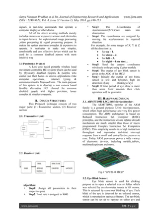
The tilt is sensed by a digital accelerometer
MMA8451Q. The MMA8451Q is a I2C based low
cost accelerometer that is connected with the ADC of
the LPC2148 microcontroller. it senses tilt and tilt
angle. Each axis (i.e. X Y Z) can sense 90 degrees of
tilt. This is more than adequate for the head tilt
mouse since it is unlikely someone would want or be
able to move their head that much. Also, the chip is
sensitive enough for real-time use and has been used
in applications like real-time Robot balancing [9].
Depending upon the user‘s comfortably
sensitivity of accelerometer is set which decides the
cursor movement.
Table 1.Sensitivity values of accelerometer for
cursor movement
Axis values Symbol to
PC
Operation
Y>5 Sends 1 Cursor moves
upward
Y<2 Sends 2 Cursor moves
downward
X<-5 Sends 3 Cursor moves
Left
X>5 Sends 4 moves Right
Mouse clicking is actuated by eye-blink,
which is one of the most natural phenomenon human
behaviour. It based on Infrared radiation from eye.
Fig.5".IR mechanism"
The object here is treated as the eye, upon
which IR ray falls reflection signal is collected by the
photodetector.The received signal is sent to the
signal processing circuit that comprises of an Op-
amp or comparator(LM358 most probably).The
comparator is used to amplify the low strength
received signal makes it strengthen enough to send to
the ADC Microcontroller(LPC2148) which operates
on 3.3v.When the user close his/her eyes the output
of the eye blink sensor is high and keeping this
condition up to some define time interval clicking
operation is generated.
V. SOFTWARE DESIGN:
ALGORITHM FOR MOUSE INTERFACING
IN VISUAL C#:
Step1: Create an object of serial port class
Step2: Connect to the provided com port with this
object by passing parameter values.
Step3: Received data through serial port
Step4: Get the current (x, y) co-ordinates of mouse
cursors
Step5: The mouse cursor moves to the direction by
received data from serial port by increases or
decreases the value of X or Y
Step6: For example
when it receives 1,then it will move upwards,
having co-ordinatesX,Y+1,
When it receives 2 then it will move down-
word having the coordinate x, y-1.
When it receives 3 then it will move left
having the coordinate x-1, y.
When it receives 4 then it will move right
having the coordinate x+1, y.
Step7: Now For Clicking purpose import
SYSTEM32.DLL into the program.
Step8: when it gets proper value of timer, it will do
required click operation
Step9: Now one can move cursor, click and open a
folder
Keil uvision: Keil simulator is used for the purpose
of coding ARM7 LPC2148 microcontroller unit.
Flash magic: This software is used to dump the hex
code generated from keil into LPC2148 MCU.
Flow chart:
5.1.Experiment Setup & Results:
Fig.6 "accelerometer values at different head
positions"](https://image.slidesharecdn.com/z4501149153-140716025200-phpapp02/85/Z4501149153-4-320.jpg)
![Surya Narayan Pradhan et al Int. Journal of Engineering Research and Applications www.ijera.com
ISSN : 2248-9622, Vol. 4, Issue 5( Version 1), May 2014, pp.149-153
www.ijera.com 153 | P a g e
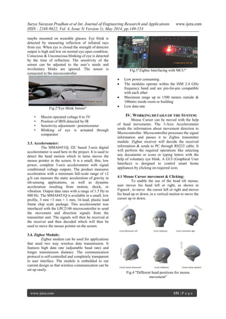
‗
Fig 7".Hardware setup of wearable HCI system "
VI. Conclusion
The HCI is an evolving area of research
interest nowadays. This project aims to be a
convenient process for helping out the disabled to
operate computers. These systems can also be used
in other application like robotics efforts, in process to
make the device cost effective and more complex
thereby reducing the size. Thus We have developed a
real hand free mouse. This paper will be very
effective and accurate using of both MEMS and eye
blink sensors as a wireless mouse for future
generation machines.
6.1 Future Scope:
Human Computer Interaction is gaining
mass popularity in the present days. This project
provides a greater scope for improvement in the near
future. Effective control of mouse cursor with speech
recognition & increasing of writing speed are still
some sectors to be improved in future. Better
methods of transmission and reception channel can
also be developed on further experiment.
REFERENCES
[1] O. K. Oyekoya and F. W. M. Stentiford,
―Eye tracking—A new interface for visual
exploration,‖ BT Technol. J., vol. 24, no. 3,
pp. 57–66, 2006.
[2] M. W. Johns, A. Tucker, J. R. Chapman, E.
K. Crowley, and N. Michael,―Monitoring
eye and eyelid movements by infrared
reflectance oculography to measure
drowsiness in drivers,‖. Somnologie
SchlafforschungSchlafmedizin, vol. 11, pp.
234–242, 2007
[3] Shang-Lin Wu†, Lun-De Liao, Shao-Wei
Lu, Wei-Ling Jiang, Shi-An Chen
―Controlling a Human–Computer Interface
System With a Novel Classification Method
that Uses Electrooculography
Signals‖.IEEE,2013
[4] L. Y. Deng, C. L. Hsu, T. C. Lin, J. S. Tuan,
and S. M. Chang, ―EOG-based human–
computer interface system development,‖
Expert Syst. Appl.,vol. 37, pp. 3337–3343,
Apr. 2010
[5] A. B. Barreto, S. D. Scargle, and M.
Adjouadi, ―A practical emg-basedhuman-
computer interface for users with motor
disabilities,‖ J. Rehabil. Res. Dev., vol. 37,
no. 1, pp. 53–64, Jan./Feb. 2000
[6] Ville Rantanen, Toni Vanhala, Outi Tuisku,
Pekka-Henrik Niemenlehto, Jarmo Verho,
Veikko Surakka,Martti Juhola, and Jukka
Lekala ―A Wearable, Wireless Gaze
Tracker with Integrated Selection
Command Source for Human-Computer
Interaction”.IEEE transactions on
INFORMATION TECHNOLOGY IN
BIOMEDICINE, VOL. 15, NOk. 5,
SEPTEMBER 2011
[7] E. Ianez, J. M. Azorın, A. U beda, J. M.
Ferrandez, and E. Fernandez,―Mental tasks-
based brain–robot interface,‖ Robot. Auton.
Syst., vol. 58, no. 12, pp. 1238–1245, 2010
[8] Natural Eye Movement & its application for
paralyzed patients, Yash Shaileshkumar
Desai.IJETT April 2013
[9] Memsic 2125 Accelerometer Demo Kit
(#28017), Parallax Inc., 2004.
[10] www.microbuilder.eu
[11] www.ocfreaks.com
[12] www.zembedded.com](https://image.slidesharecdn.com/z4501149153-140716025200-phpapp02/85/Z4501149153-5-320.jpg)

This paper presents the design and implementation of a low-cost wireless human-computer interface (HCI) system for disabled individuals, utilizing head movements and eye blinks for navigation and interaction. The system consists of a tilt sensor to detect head movements and an eye blink sensor to facilitate clicking, both transmitting data to a microcontroller via Zigbee technology. The proposed solution aims to provide a more intuitive and affordable means of computer interaction for people with upper limb motor paralysis.