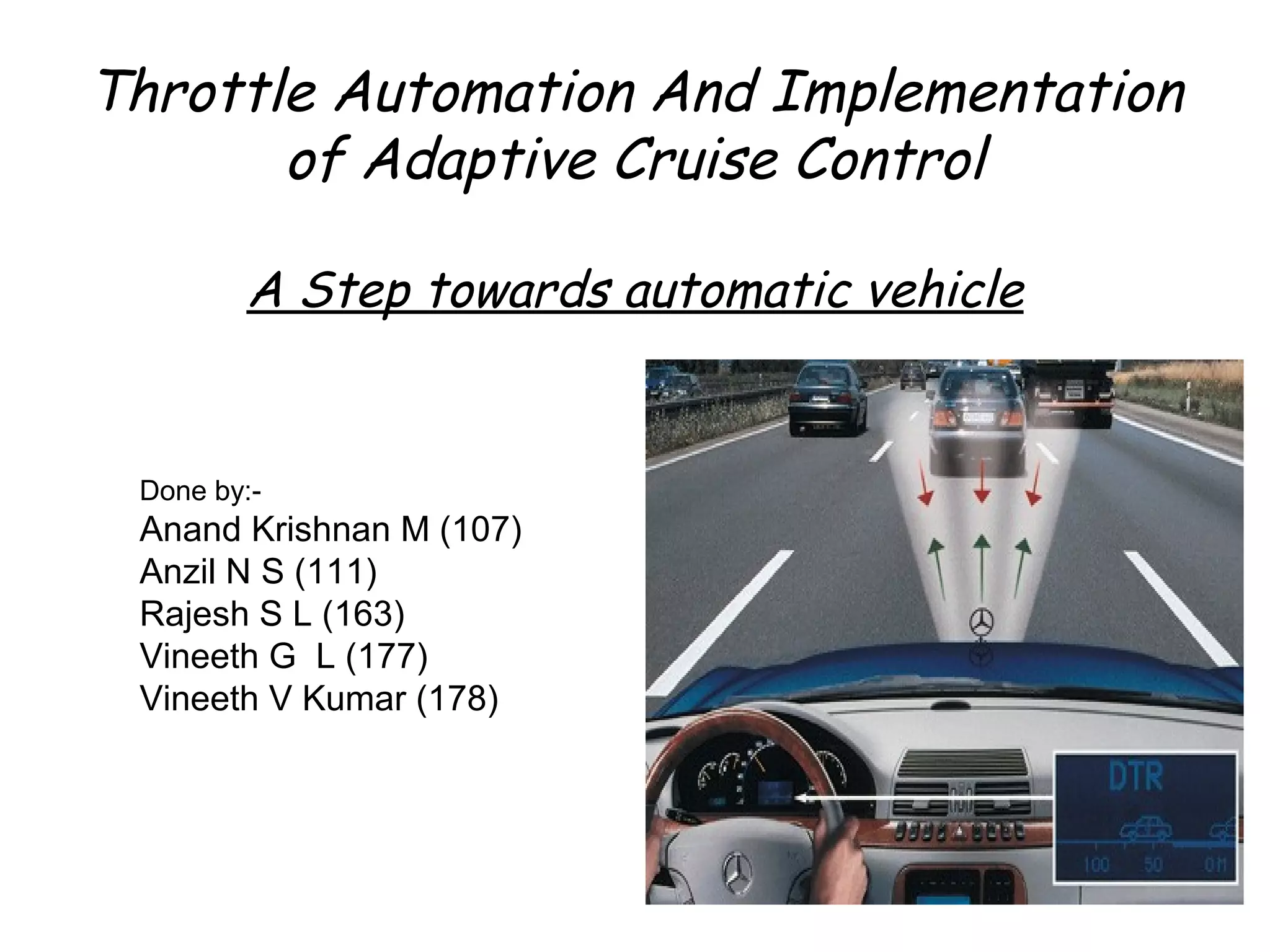
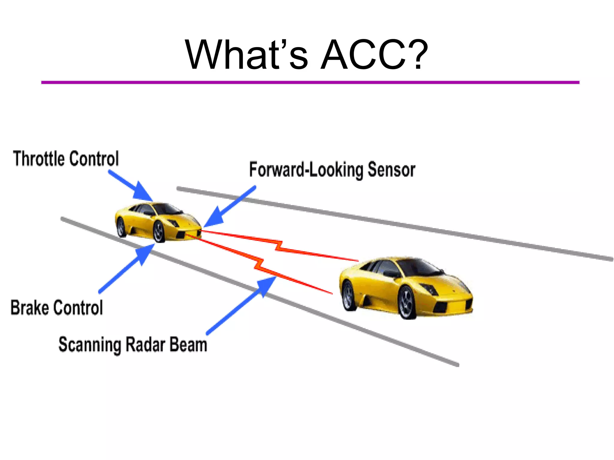
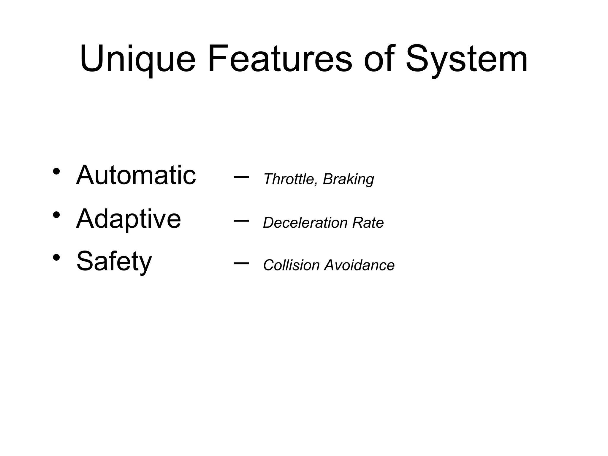
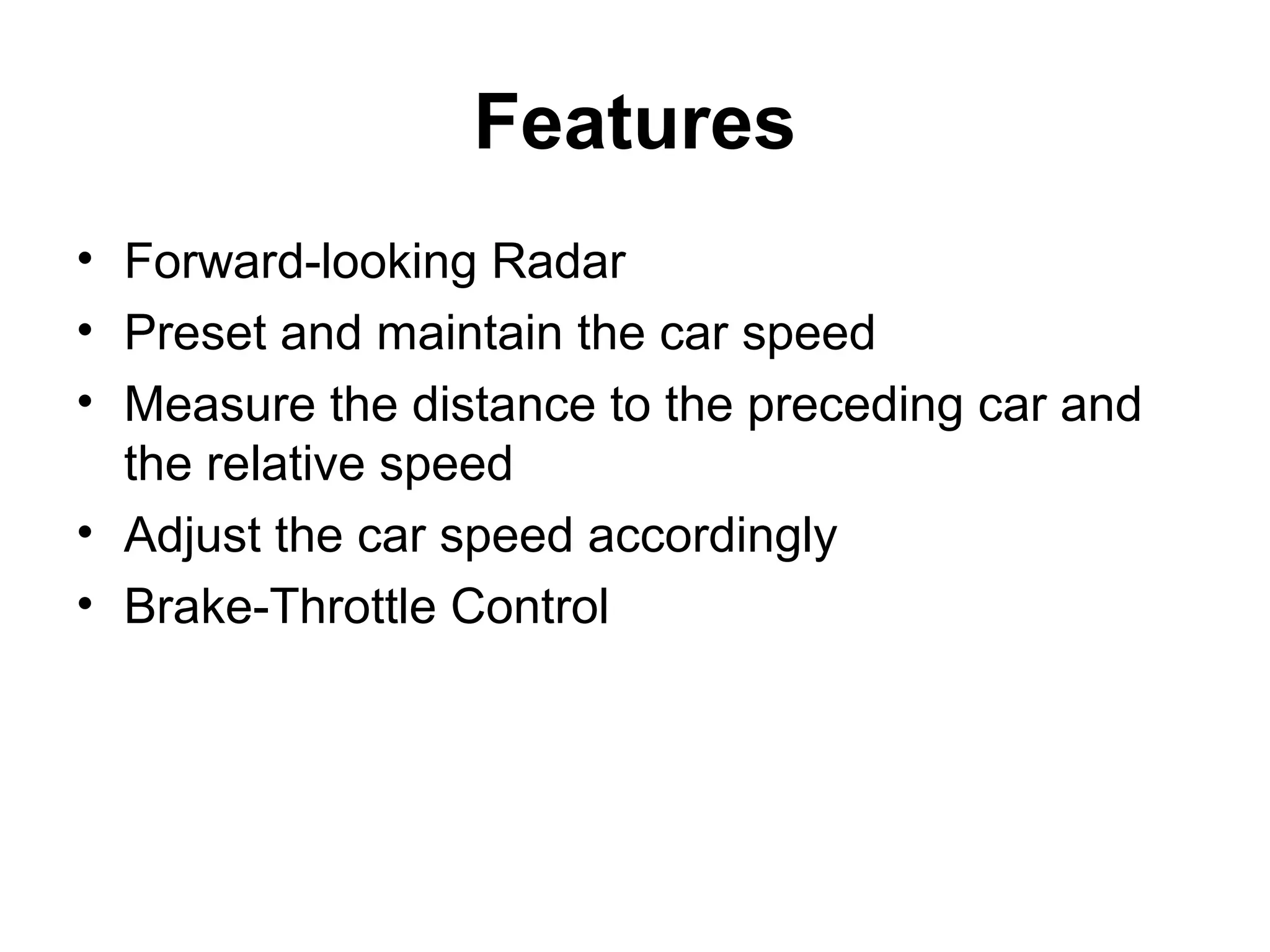
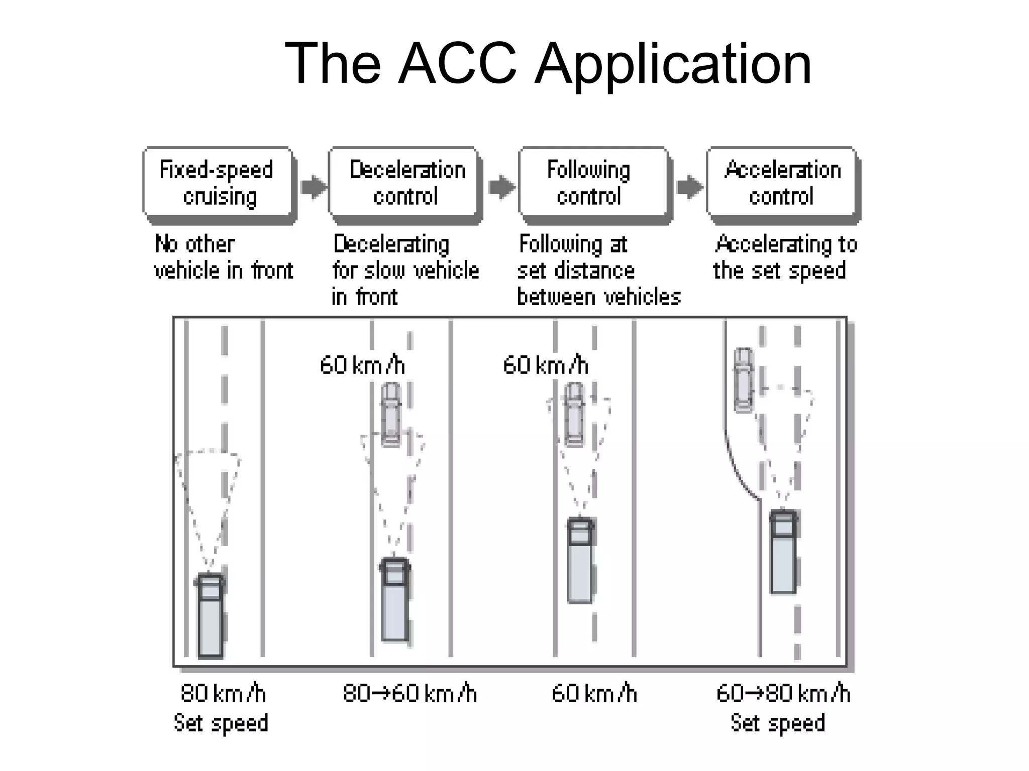
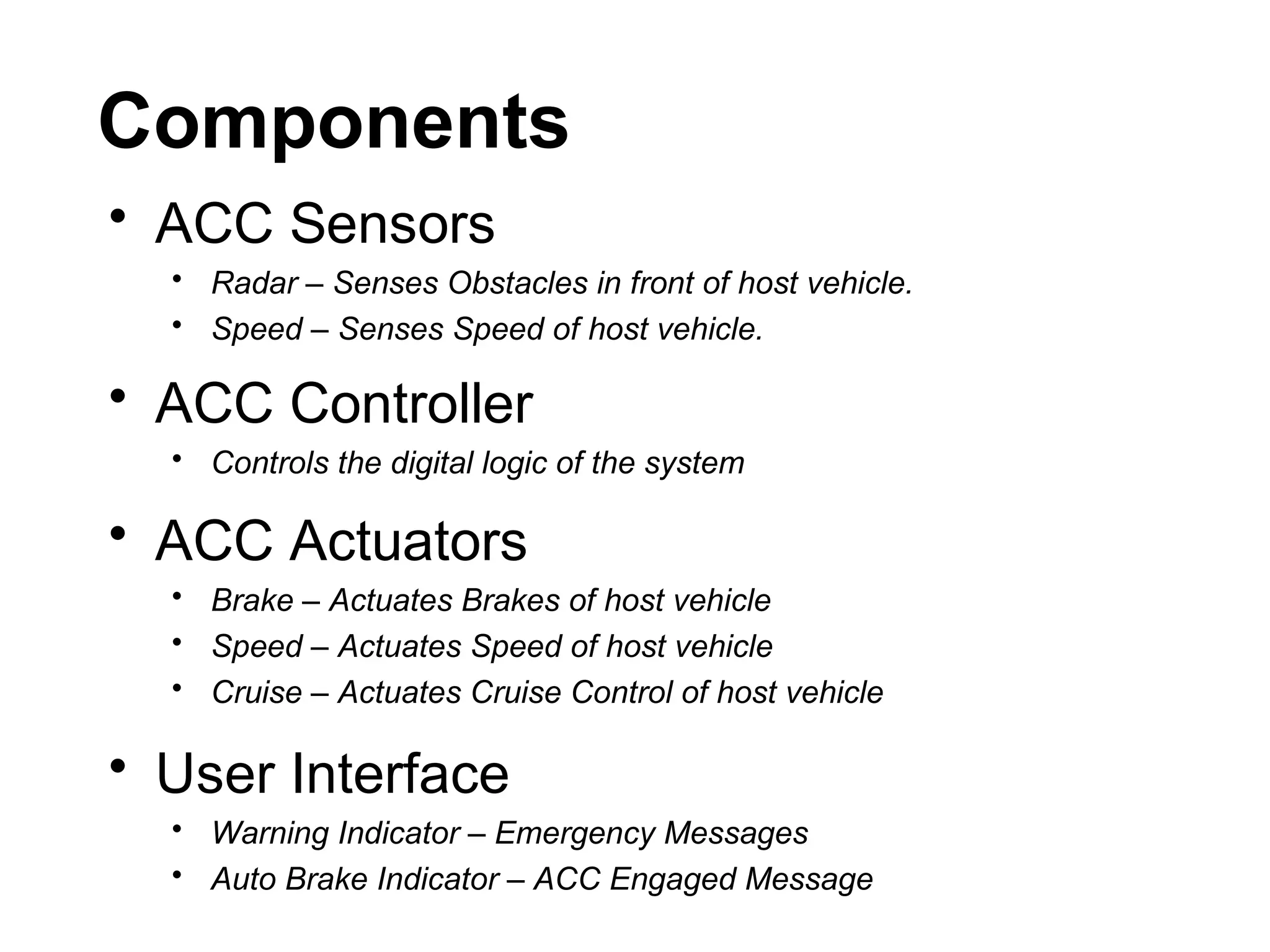
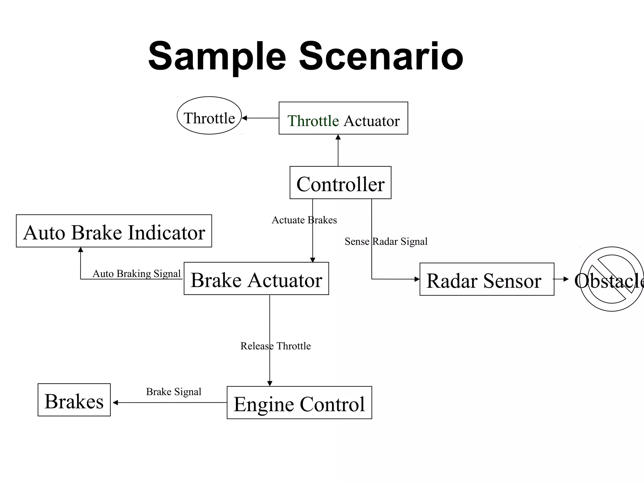
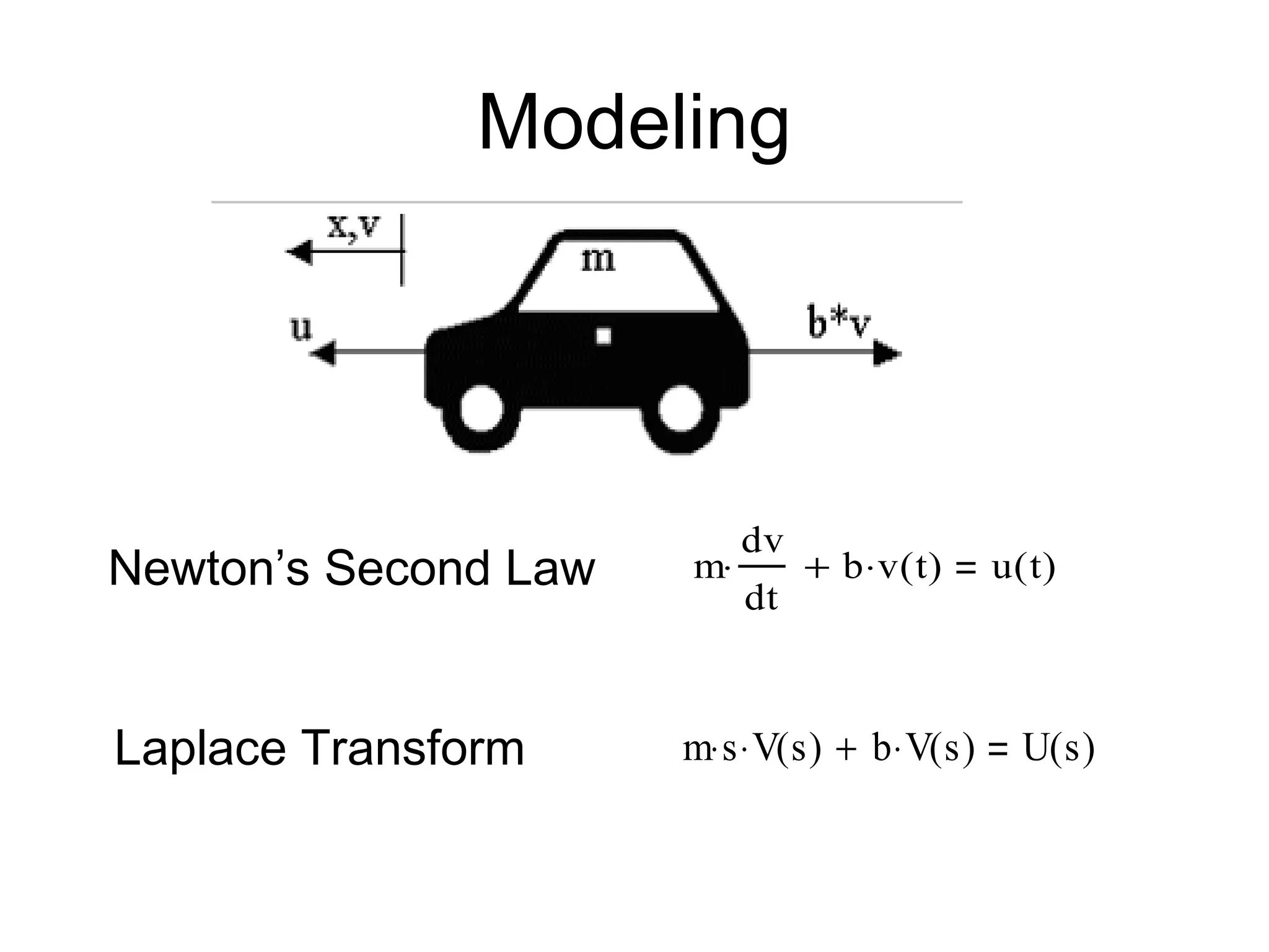
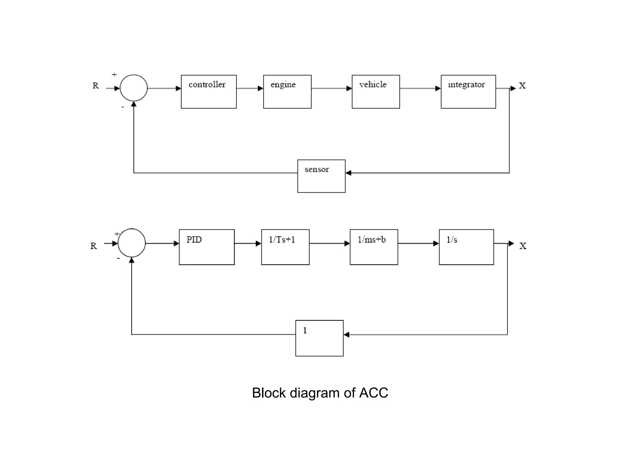
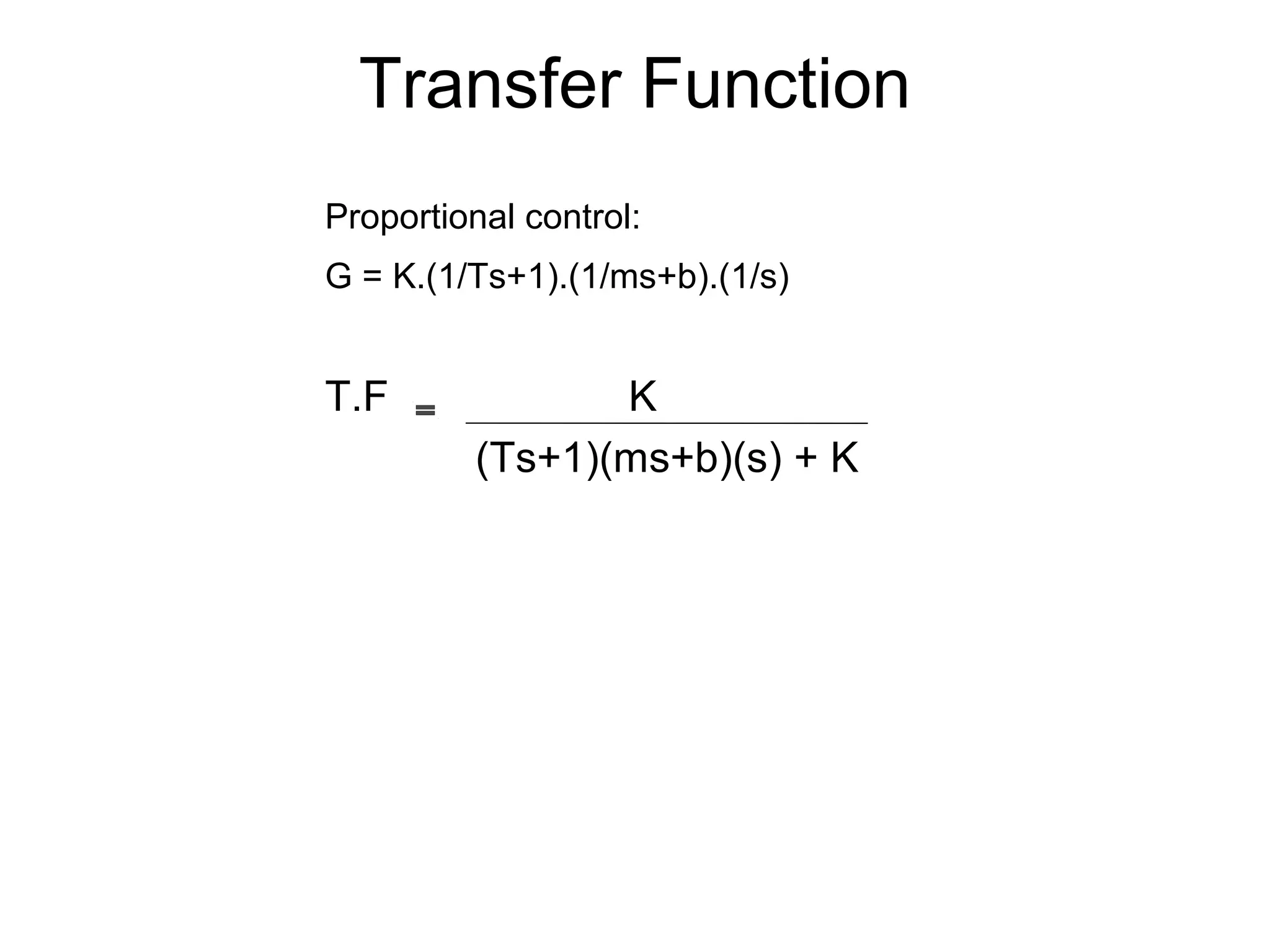
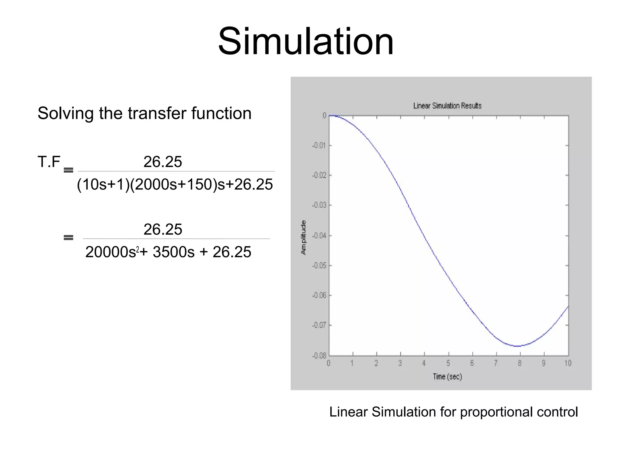
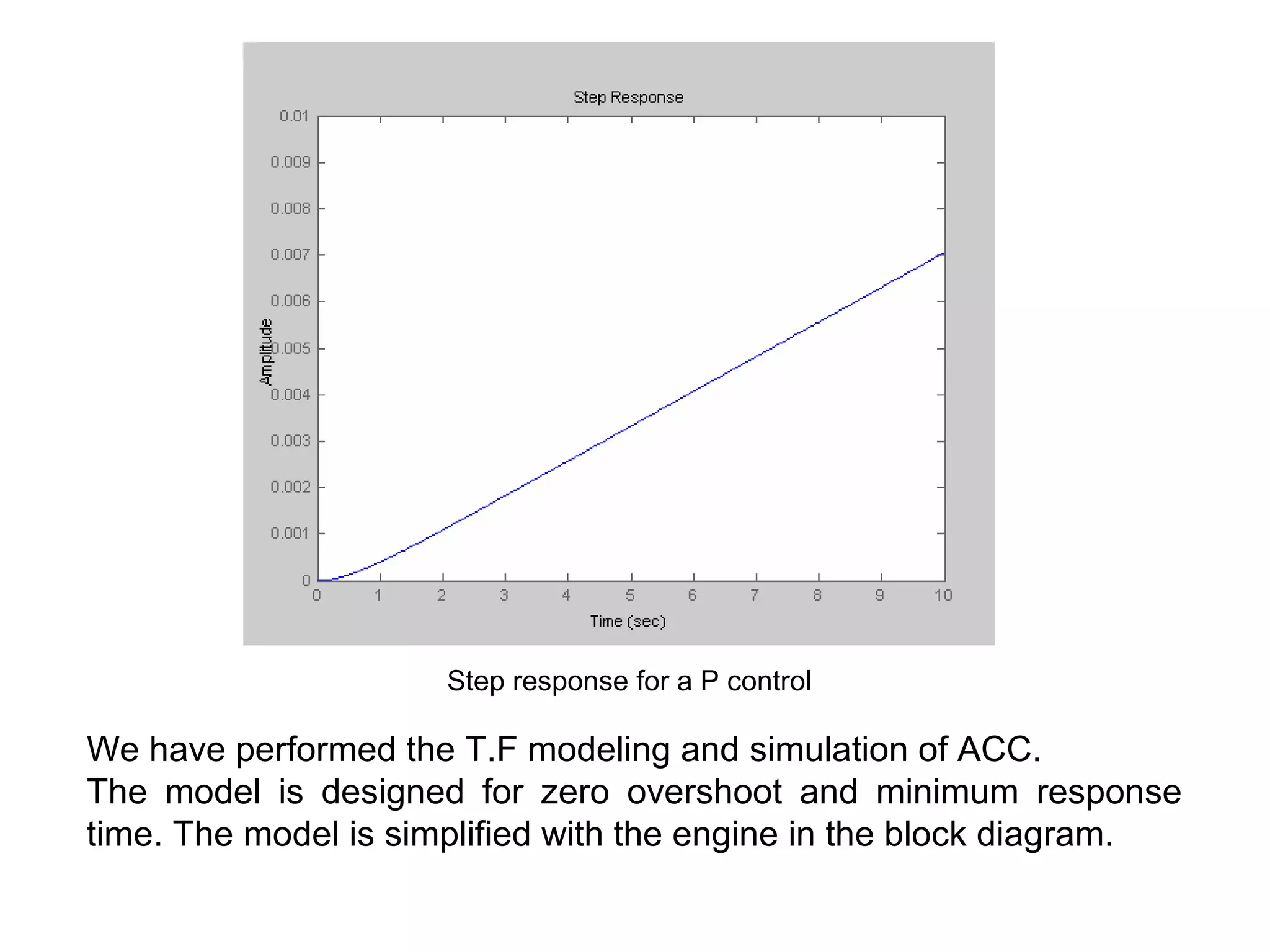
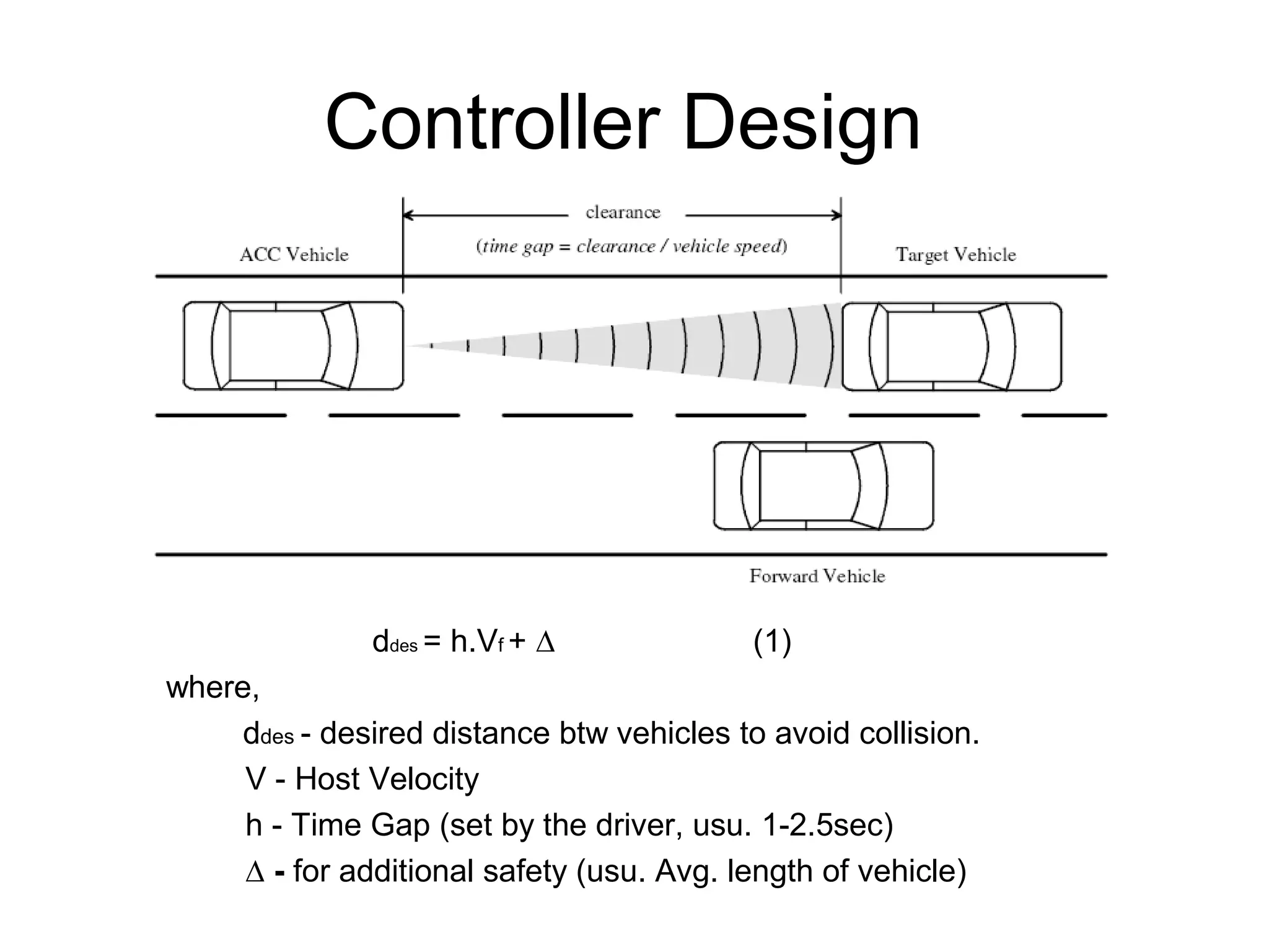
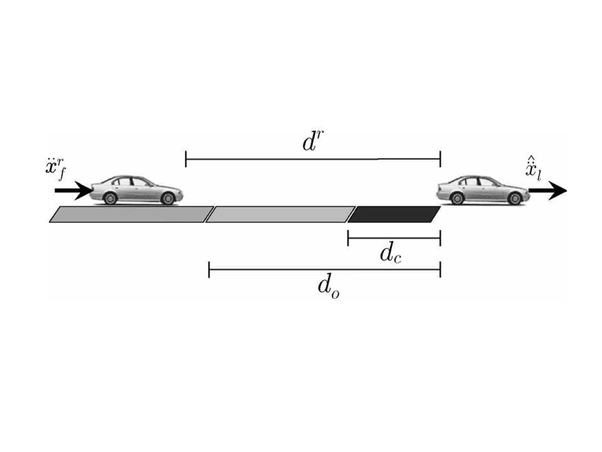
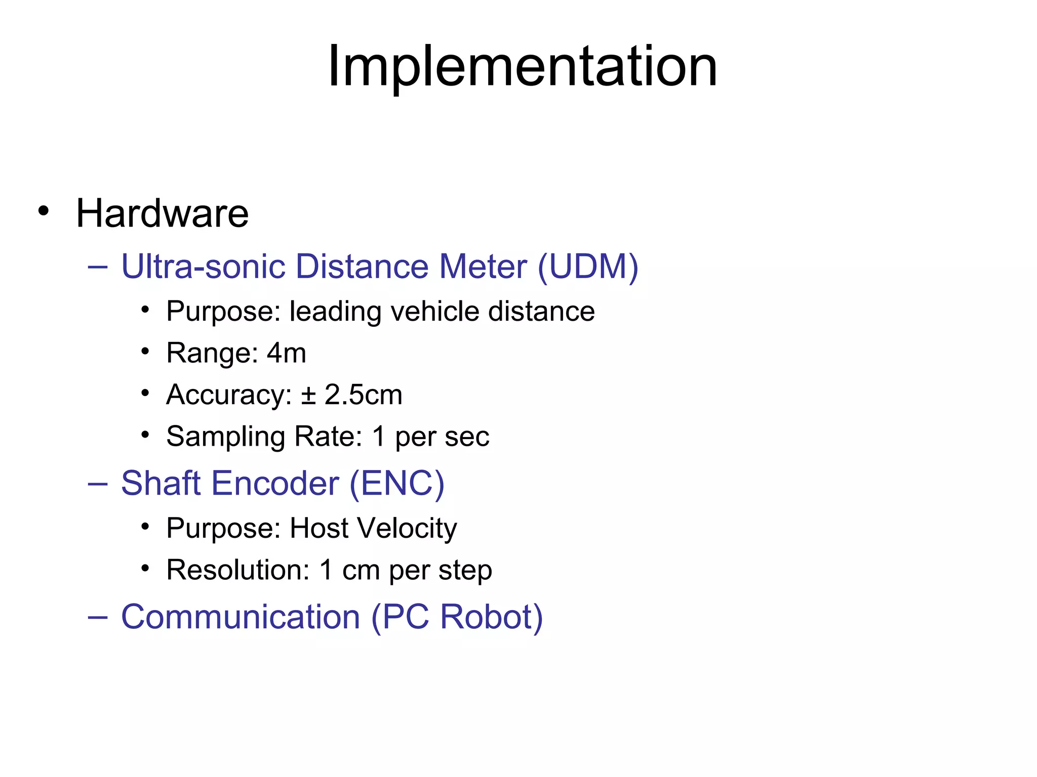
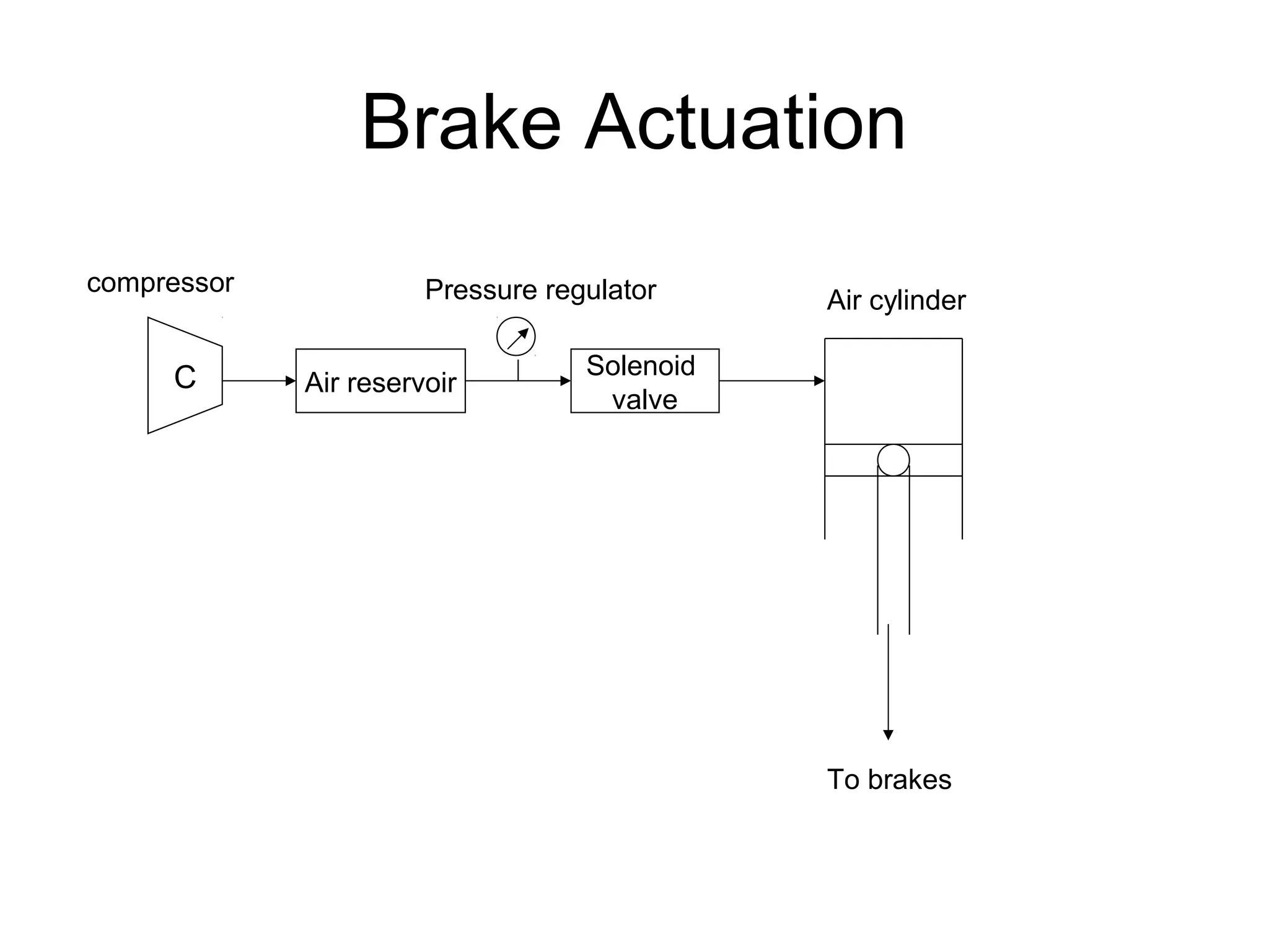
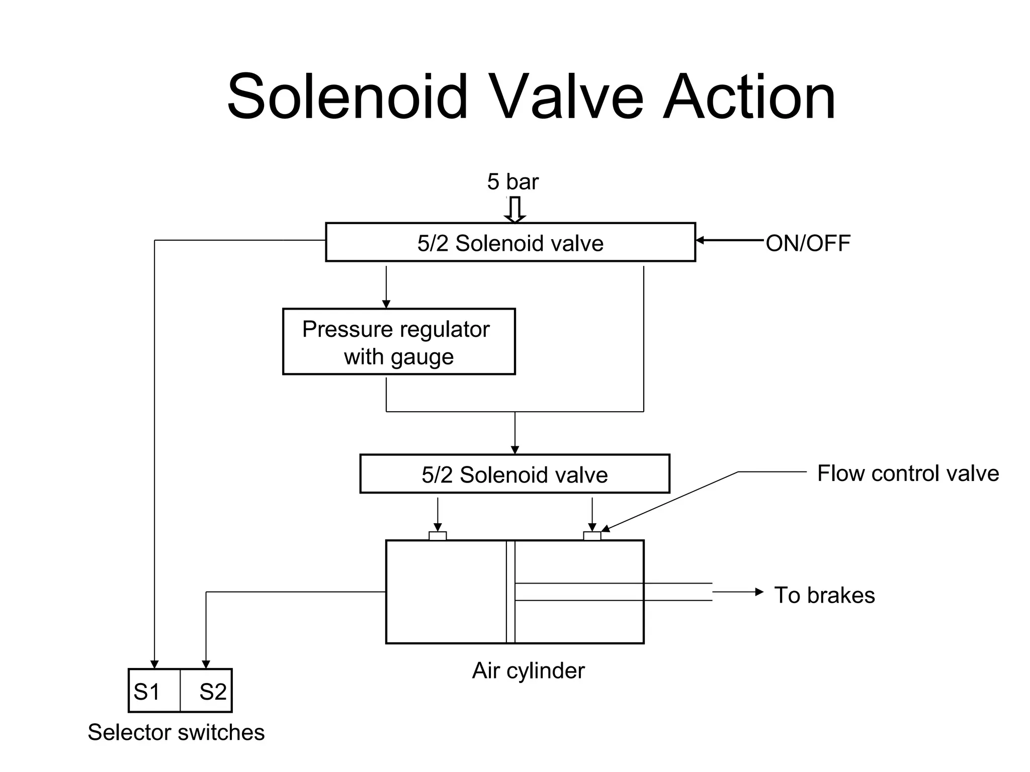
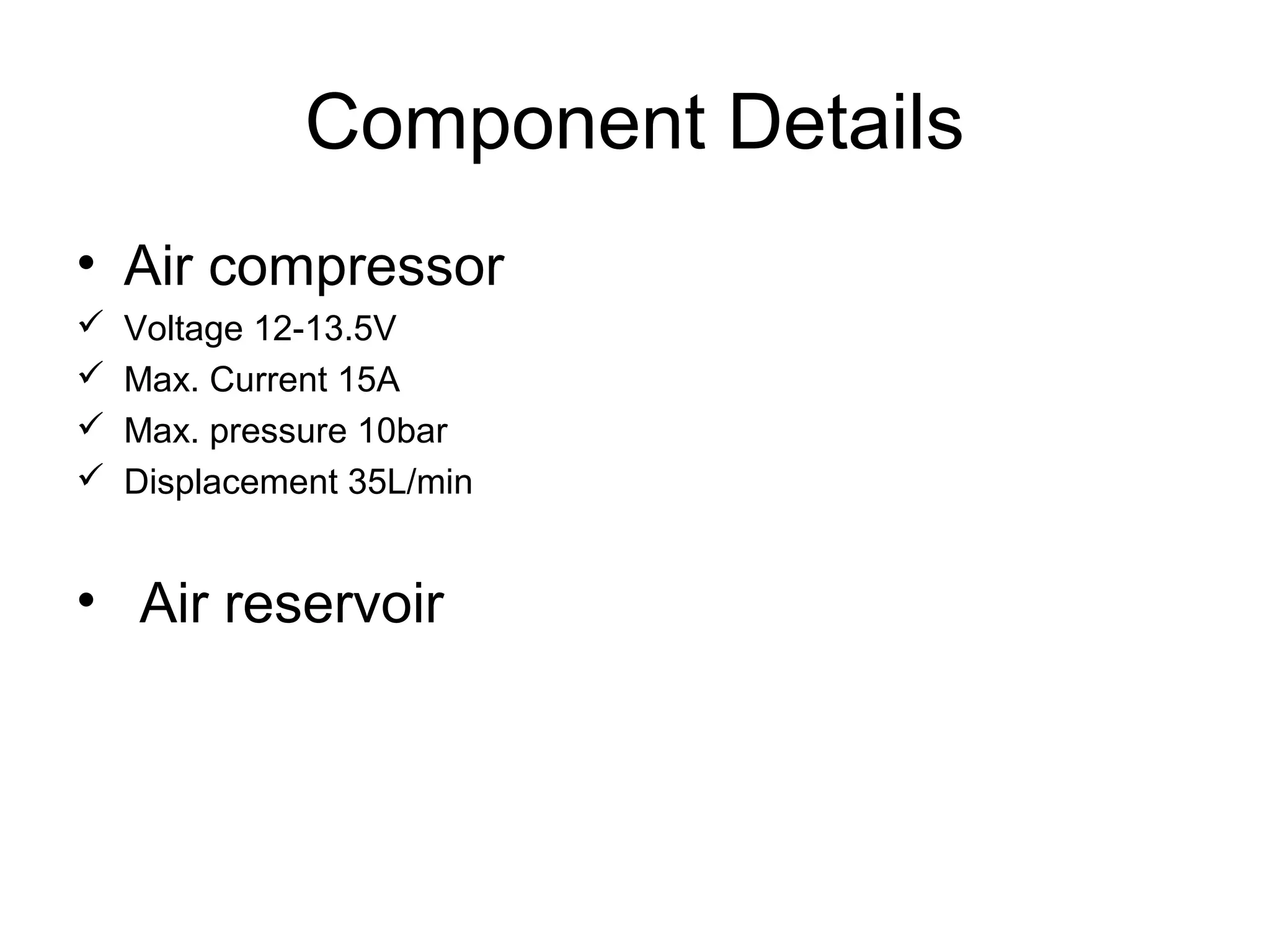
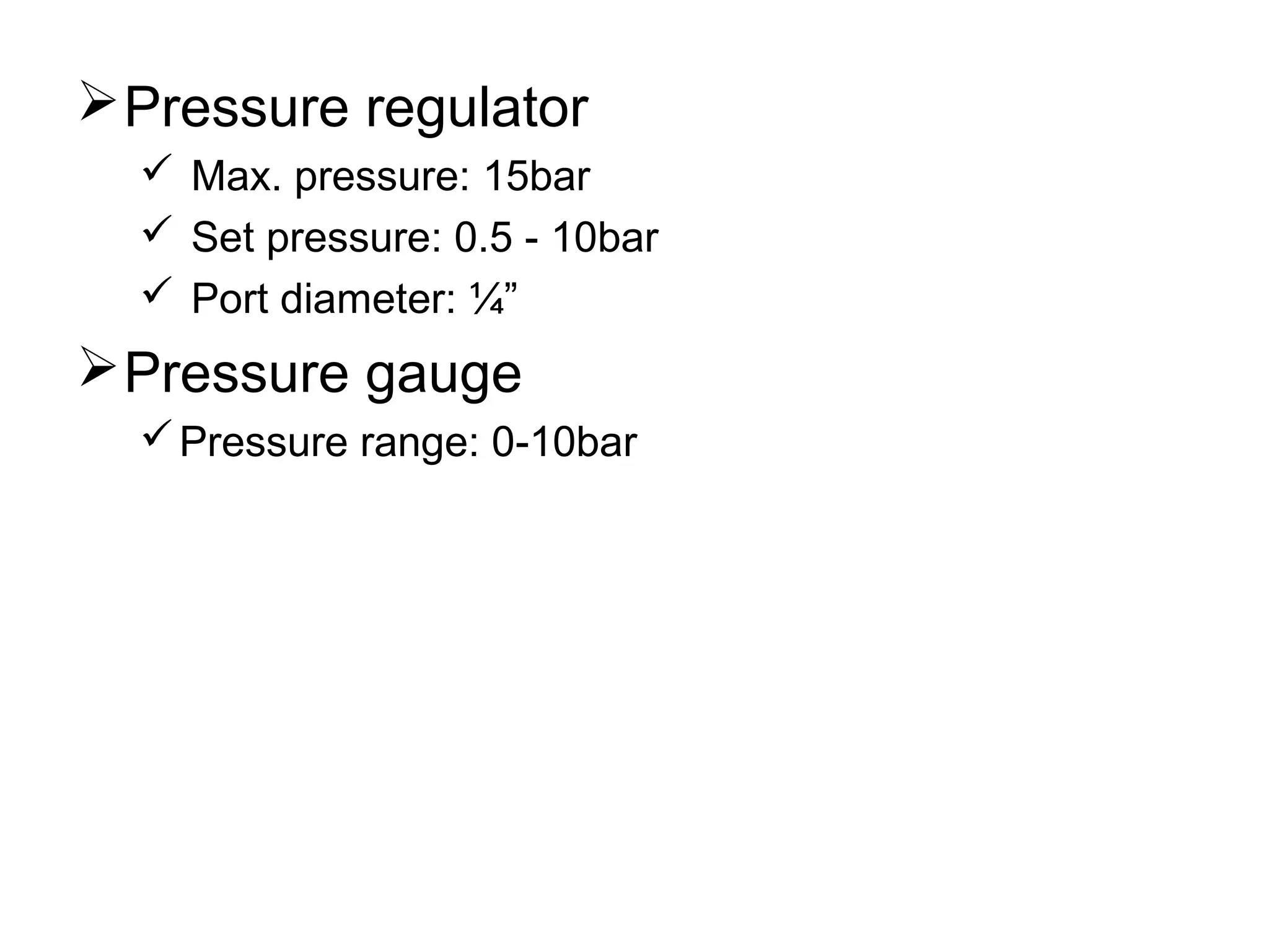
Throttle Automation And Implementation
of Adaptive Cruise Control
A Step towards automatic vehicle
Done by:-
Anand Krishnan M (107)
Anzil N S (111)
Rajesh S L (163)
Vineeth G L (177)
Vineeth V Kumar (178)
Overview
• Introduction
• Components
• Modelling
• Simulation
• Design
• Implementation
• Further Work
• References
What’s ACC?
Unique Features of System
• Adaptive – Deceleration Rate
• Safety – Collision Avoidance
• Automatic – Throttle, Braking
Features
• Forward-looking Radar
• Preset and maintain the car speed
• Measure the distance to the preceding car and
the relative speed
• Adjust the car speed accordingly
• Brake-Throttle Control
The ACC Application
Components
• ACC Sensors
• Radar – Senses Obstacles in front of host vehicle.
• Speed – Senses Speed of host vehicle.
• ACC Controller
• Controls the digital logic of the system
• ACC Actuators
• Brake – Actuates Brakes of host vehicle
• Speed – Actuates Speed of host vehicle
• Cruise – Actuates Cruise Control of host vehicle
• User Interface
• Warning Indicator – Emergency Messages
• Auto Brake Indicator – ACC Engaged Message
ObstacleRadar Sensor
Controller
Brake Actuator
Engine ControlBrakes
Sense Radar Signal
Actuate Brakes
Release Throttle
Brake Signal
Sample Scenario
Auto Brake Indicator
Auto Braking Signal
Throttle ActuatorThrottle
Modeling
m s⋅ V s( )⋅ b V s( )⋅+ U s( )
Newton’s Second Law m
dv
dt
⋅ b v t( )⋅+ u t( )
Laplace Transform
Block diagram of ACC
Proportional control:
G = K.(1/Ts+1).(1/ms+b).(1/s)
T.F K
(Ts+1)(ms+b)(s) + K
Transfer Function
Simulation
Solving the transfer function
T.F 26.25
(10s+1)(2000s+150)s+26.25
26.25
20000s2
+ 3500s + 26.25
Linear Simulation for proportional control
Step response for a P control
We have performed the T.F modeling and simulation of ACC.
The model is designed for zero overshoot and minimum response
time. The model is simplified with the engine in the block diagram.
Controller Design
ddes = h.Vf + ∆ (1)
where,
ddes - desired distance btw vehicles to avoid collision.
V - Host Velocity
h - Time Gap (set by the driver, usu. 1-2.5sec)
∆ - for additional safety (usu. Avg. length of vehicle)
Implementation
• Hardware
– Ultra-sonic Distance Meter (UDM)
• Purpose: leading vehicle distance
• Range: 4m
• Accuracy: ± 2.5cm
• Sampling Rate: 1 per sec
– Shaft Encoder (ENC)
• Purpose: Host Velocity
• Resolution: 1 cm per step
– Communication (PC Robot)
Brake Actuation
C Air reservoir
Solenoid
valve
Pressure regulator Air cylinder
To brakes
compressor
Solenoid Valve Action
5/2 Solenoid valve
5 bar
ON/OFF
Pressure regulator
with gauge
5/2 Solenoid valve Flow control valve
S1 S2
Selector switches
To brakes
Air cylinder
Component Details
• Air compressor
 Voltage 12-13.5V
 Max. Current 15A
 Max. pressure 10bar
 Displacement 35L/min
• Air reservoir
Pressure regulator
 Max. pressure: 15bar
 Set pressure: 0.5 - 10bar
 Port diameter: ¼”
Pressure gauge
Pressure range: 0-10bar
Solenoid valve
 5/2 single solenoid
 Voltage: 12 V
 Power:
 Max. pressure: 10 bar
 Diameter: ¼”
Air cylinder
 Double acting
 Bore: 40 mm
 Stroke: 15 mm
 Make: Janatics
 Port diameter: ¼”
 Max. pressure: 10 bar
 Flow control valves
 Silencer type
 With lock nut
 Fittings
 Male connector (Dia 6 x ¼”)
 Male elbow (6 x 1/8”)
 Pneumatic line (6 mm dia.)
Hardware Details
Advantages
• Function properly in poor weather condition
• Conventional Cruise Control operation may be canceled
automatically or by the operator under the following
conditions
 Brake pedal is pressed
 'Off' button is pressed
 Vehicle Speed < 25 mph
 An ACC system fault is detected
Further Work
• More experiments to evaluate the design.
• Implementation on a geared 2 wheeler.
• Implementation on a 4 wheeler.
• Modelling with PD & PID controllers.
References
• 5th Meeting of the U.S. Software System Safety Working
Group, April 12th-14th 2005 @ Anaheim, California USA
• Petros Ioannou; Cheng-Chih Chien. “Autonomous Intelligent
Cruise Control”. IEEE Trans. On Vehicular Technology,
42(4):657-672, 1993.
THANK YOU

Fair ppt

  • 1.
    Throttle Automation AndImplementation of Adaptive Cruise Control A Step towards automatic vehicle Done by:- Anand Krishnan M (107) Anzil N S (111) Rajesh S L (163) Vineeth G L (177) Vineeth V Kumar (178)
  • 2.
    Overview • Introduction • Components •Modelling • Simulation • Design • Implementation • Further Work • References
  • 3.
  • 4.
    Unique Features ofSystem • Adaptive – Deceleration Rate • Safety – Collision Avoidance • Automatic – Throttle, Braking
  • 5.
    Features • Forward-looking Radar •Preset and maintain the car speed • Measure the distance to the preceding car and the relative speed • Adjust the car speed accordingly • Brake-Throttle Control
  • 6.
  • 7.
    Components • ACC Sensors •Radar – Senses Obstacles in front of host vehicle. • Speed – Senses Speed of host vehicle. • ACC Controller • Controls the digital logic of the system • ACC Actuators • Brake – Actuates Brakes of host vehicle • Speed – Actuates Speed of host vehicle • Cruise – Actuates Cruise Control of host vehicle • User Interface • Warning Indicator – Emergency Messages • Auto Brake Indicator – ACC Engaged Message
  • 8.
    ObstacleRadar Sensor Controller Brake Actuator EngineControlBrakes Sense Radar Signal Actuate Brakes Release Throttle Brake Signal Sample Scenario Auto Brake Indicator Auto Braking Signal Throttle ActuatorThrottle
  • 9.
    Modeling m s⋅ Vs( )⋅ b V s( )⋅+ U s( ) Newton’s Second Law m dv dt ⋅ b v t( )⋅+ u t( ) Laplace Transform
  • 10.
  • 11.
    Proportional control: G =K.(1/Ts+1).(1/ms+b).(1/s) T.F K (Ts+1)(ms+b)(s) + K Transfer Function
  • 12.
    Simulation Solving the transferfunction T.F 26.25 (10s+1)(2000s+150)s+26.25 26.25 20000s2 + 3500s + 26.25 Linear Simulation for proportional control
  • 13.
    Step response fora P control We have performed the T.F modeling and simulation of ACC. The model is designed for zero overshoot and minimum response time. The model is simplified with the engine in the block diagram.
  • 14.
    Controller Design ddes =h.Vf + ∆ (1) where, ddes - desired distance btw vehicles to avoid collision. V - Host Velocity h - Time Gap (set by the driver, usu. 1-2.5sec) ∆ - for additional safety (usu. Avg. length of vehicle)
  • 16.
    Implementation • Hardware – Ultra-sonicDistance Meter (UDM) • Purpose: leading vehicle distance • Range: 4m • Accuracy: ± 2.5cm • Sampling Rate: 1 per sec – Shaft Encoder (ENC) • Purpose: Host Velocity • Resolution: 1 cm per step – Communication (PC Robot)
  • 17.
    Brake Actuation C Airreservoir Solenoid valve Pressure regulator Air cylinder To brakes compressor
  • 18.
    Solenoid Valve Action 5/2Solenoid valve 5 bar ON/OFF Pressure regulator with gauge 5/2 Solenoid valve Flow control valve S1 S2 Selector switches To brakes Air cylinder
  • 19.
    Component Details • Aircompressor  Voltage 12-13.5V  Max. Current 15A  Max. pressure 10bar  Displacement 35L/min • Air reservoir
  • 20.
    Pressure regulator  Max.pressure: 15bar  Set pressure: 0.5 - 10bar  Port diameter: ¼” Pressure gauge Pressure range: 0-10bar
  • 21.
    Solenoid valve  5/2single solenoid  Voltage: 12 V  Power:  Max. pressure: 10 bar  Diameter: ¼”
  • 22.
    Air cylinder  Doubleacting  Bore: 40 mm  Stroke: 15 mm  Make: Janatics  Port diameter: ¼”  Max. pressure: 10 bar
  • 23.
     Flow controlvalves  Silencer type  With lock nut  Fittings  Male connector (Dia 6 x ¼”)  Male elbow (6 x 1/8”)  Pneumatic line (6 mm dia.)
  • 24.
  • 25.
    Advantages • Function properlyin poor weather condition • Conventional Cruise Control operation may be canceled automatically or by the operator under the following conditions  Brake pedal is pressed  'Off' button is pressed  Vehicle Speed < 25 mph  An ACC system fault is detected
  • 26.
    Further Work • Moreexperiments to evaluate the design. • Implementation on a geared 2 wheeler. • Implementation on a 4 wheeler. • Modelling with PD & PID controllers.
  • 27.
    References • 5th Meetingof the U.S. Software System Safety Working Group, April 12th-14th 2005 @ Anaheim, California USA • Petros Ioannou; Cheng-Chih Chien. “Autonomous Intelligent Cruise Control”. IEEE Trans. On Vehicular Technology, 42(4):657-672, 1993.
  • 28.

Editor's Notes

  • #4 First, what is an ACC system? ACC system is the most widely used term for systems which are equipped with forward-looking radar and can automatically change engine speed and/or apply brakes to achieve preset speed or inter-vehicle headway. Second, why are people interested in ACC? Basically, conventional cruise control system can not be used in heavy traffic. So people hope ACC can solve this problem. While Automakers said ACC is used to reduce fatigue, provide alert and enhance comfort, traffic operators are more interested in the potential benefit of ACC in passenger safety and traffic capacity.