Downloaded 33 times


![53
www.belman.comB022016-1 – Subject to alterations and eventual misprints
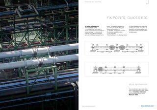
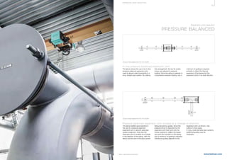
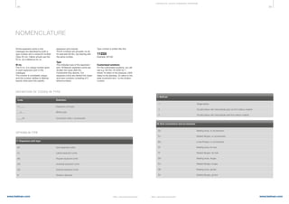
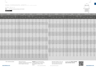
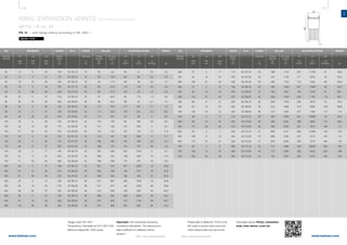
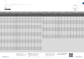
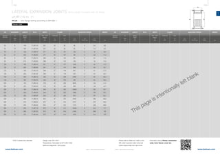
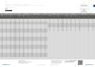
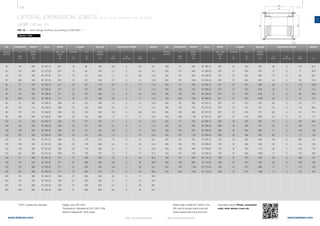
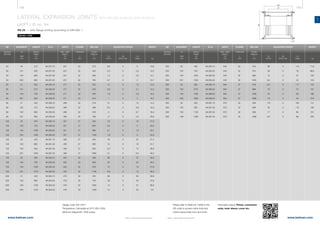
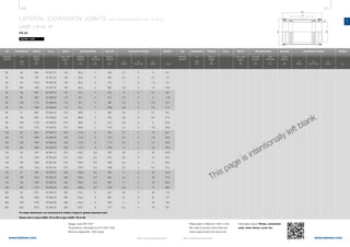
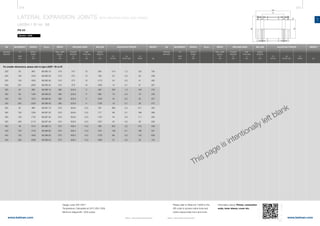
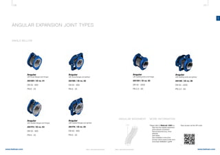
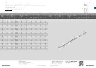
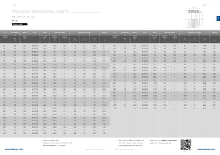
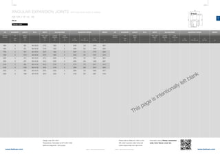
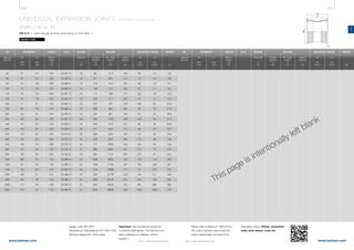
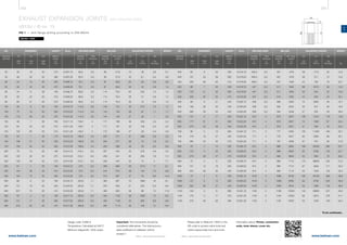
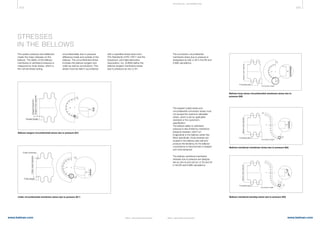
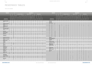
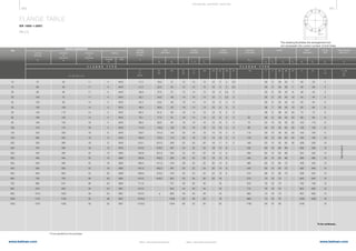
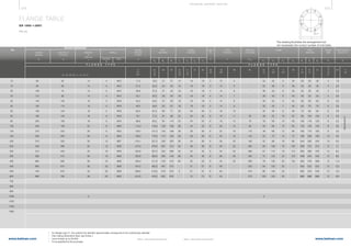
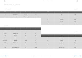
MATERIAL
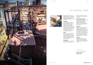
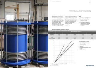
Source: EN 14917:2009
TYPE
Number Steel name
TEMPERATURE °C
MaximumMinimum
DOCUMENT
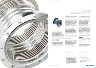
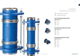
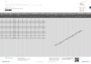
a = Minimum temperature according to EN 13445-2/Annex B or EN 13480-2/Annex B.
b = Minimum temperature according to CERN [7].
c = Minimum temperature for cold-rolled strip up to 6 mm and hot rolled sheet up to 12 mm thickness [2].
d = Special care should be exercised due to the risk of embrittlement when using the materials at elevated temperatures above 550°C.
e = Minimum temperature is possible when the specified minimum impact energy (normally 27 J) can be proved.
MATE R I A LS
TEMPERATURE LIMITS
FOR BELLOW MATERIALS
1.4301 X5CrNi18-10 -196a
550
1.4306 X2CrNi19-11 -270a
550
1.4401 X5CrNiMo17-12-2 -196a
550
1.4404 X2CrNiMo17-12-2 -270b
550
1.4435 X2CrNiMo18-14-3 -270a
550
1.4539 X1CrNiMoCuN25-20-5 -196a
550
1.4541 X6CrNiTi18-10 -270c
550
1.4550 X6CrNiNb18-10 -196a
550
1.4571 X6CrNiMoTi17-12-2 -270c
550
1.4828 X15CrNiSi20-12 -196 900d
Annex B, Position 1
X10NiCrAITi32-21 -196 600 Annex B, Position 2.1
X10NiCrAITi32-21 (H) 900d
Annex B, Position 2.2
2.4610 NiMo16Cr16Ti -196 400 EAM-0526-28
EAM-0526-43-1,
2.4819 NiMo16Cr15W -196 400 EAM-0526-18
-196 450 EAM-0526-40
(-270) (900)d
([11], [12])
2.4360 NiCu30Fe -196 425 Annex B, Position 3
2.4858 NiCr21Mo -270 540 Annex B, Position 4
1.0345 P235GH -20 400
1.0425 P265GH -20 400
1.5415 16Mo3 -20e
500
1.7335 13CrMo4-5 -20e
500
1.0565 P355NH -20 400
1.8935 P460NH -20 400
Stainless
austenitic
steels
Heat
resistant
austenitic
steels
EN 10028-7:2007
Ferritic
steels
EN 10028-2:2009
EN 10028-3:2009
Nickel
alloys
1.4876
2.4816
2.4856 NiCr22Mo9Nb
NiCr15Fe
-10 450
(-270) (900)d
([9]. [10])
EAM-0526-43-2](https://image.slidesharecdn.com/belman-expansionjointcatalogueukreducedsize-160623085016/85/Expansion-Joint-Catalogue-29-320.jpg)


![96 97
www.belman.comwww.belman.com
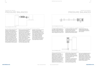
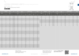
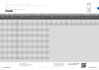
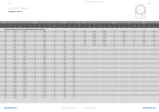
AX
B022016-1 – Subject to alterations and eventual misprintsB022016-1 – Subject to alterations and eventual misprints
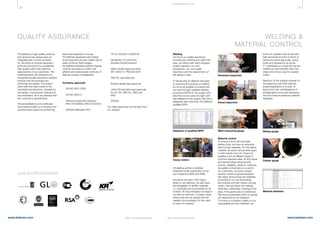
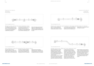
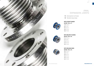
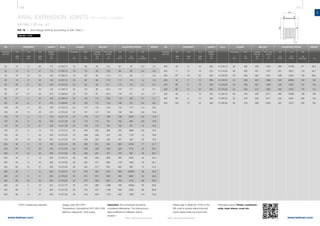
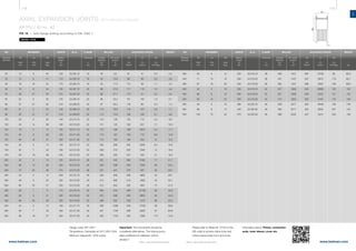
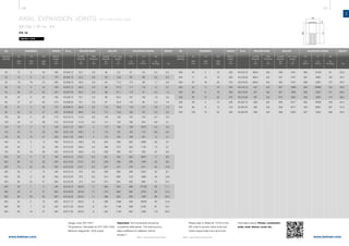
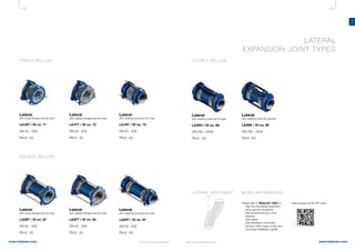
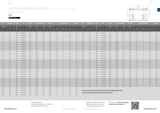
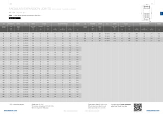
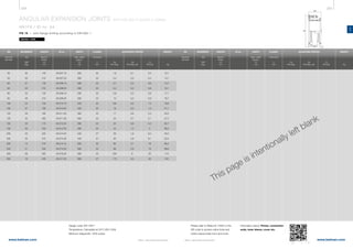
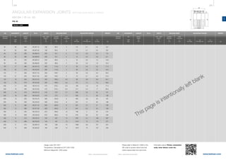
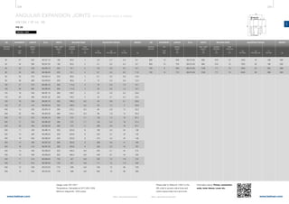
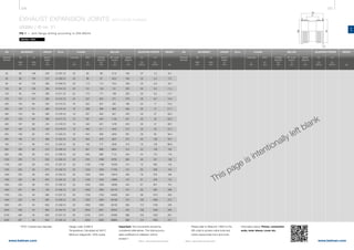
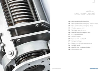
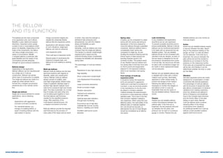
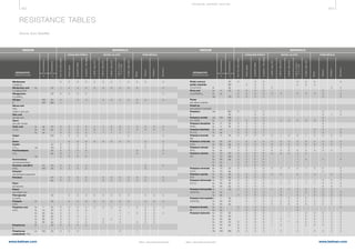
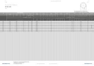
Design condition
l Design code: EN 14917
l Designed at 20°C for minimum
1000 thermal load cycles
l Arranged according nominal
pressure [PN]
l PN corresponds to the allowable
operating pressure at room
temperature [Rpt]
l Operating temperature from
-10°C to +400°C based on the
reduction factor (Kpa) from the
table on the next page
l All expansion joints are designed
to be tested at a pressure 1,43 x
the design pressure.
Where a higher test pressure is
required a unit with a higher
nominal pressure (PN) should be
selected to achieve this
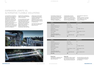
Movements
Movements are considered alternatives.
The total accumulated coefficient of
utilisation cannot exceed 1.
A 100% AX utilisation allows no lateral
movements.
Bellow
Multiply bellow in double certified
material.
Material: EN 1.4541/AISI 321 or
EN 1.4571/AISI 316 Ti
Tolerances: according to
EN ISO 13920 Class C.
Connection ends
Flanges
Loose flanges, welded flanges.
Drilling according to EN 1092.
Material: 1.0460 (C 22.8) or
1.0425 P265 GH (HII)
Surface treatment: primer coated.
Stainless steel flanges are
available on request.
Tolerances: according to norms and
standards that applies.
Welding ends
Material:
≤ DN 500: EN 1.0345/P235 GH (HI)
> DN 500: EN 1.0425/P265 GH (HII)
Surface treatment: primer coated.
Stainless steel welding ends are
available on request.
Tolerances: according to norms and
standards that applies.
STANDARD RANGE
DESIGN
We are specialised in designing and
manufacturing of customised
solutions. See selected examples
here: WebLink 13601
If the required/specified expansion
joint is not found in this product
catalogue, please do not hesitate to
forward your specifications to us.
CUSTOMISED
SOLUTIONS
Accessories
Inner sleeve, cover, counter flange,
gaskets, insulation etc. are available
on request.
Certificates
Material certificate 3.1 according to
EN 10204 and/or ASME.
PLEASE NOTE!
Vibrations
There are many ways to absorb
vibration. To know more about it,
please contact us.
Misalignment
We strongly advise against the use of
expansion joints and bellows for
misalignment.
Torsion
Torsion on bellow parts are not
desirable and should be set to zero (0).
If this cannot be avoided, please
contact us.
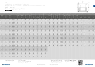
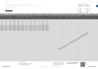
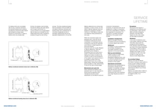
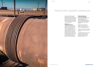
TEMPERATURE
°C
REDUCTION FACTOR
Kpa
20 1,00
100 0,83
150 0,78
200 0,74
250 0,71
300 0,67
350 0,64
400 0,62
Pressure reduction factor
The factor used for reduction of
pressure [Kpa], is based on the bellow
material yield strength at design
temperature [Rp], and the yield
strength at room temperature [Rpt].
Definiton: Kpa = Rp / Rpt
The reduction factor is applied to
modify the design pressure [PS] where
temperatures exceed 20°C, it com-
pensates for the decay in material
mechanical properties at elevated
temperatures. The modified pressure
must always be lower than the nominal
pressure of the standard item.
Calculation: PS / Kpa ≤ PN
Where the applied design pressure
is lower than the nominal pressure
for the standard unit an increase in
fatigue life expectancy and / or
increased movements can be
achieved.
Please refer to Belmaker Light®
to get an optimised solution.
On request
Please contact us, if you have any
special requirements for
eg. temperature down to -60°C,
a special combination of ends etc.](https://image.slidesharecdn.com/belman-expansionjointcatalogueukreducedsize-160623085016/85/Expansion-Joint-Catalogue-51-320.jpg)


![144 145
www.belman.comwww.belman.com
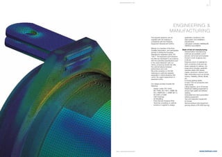
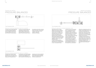
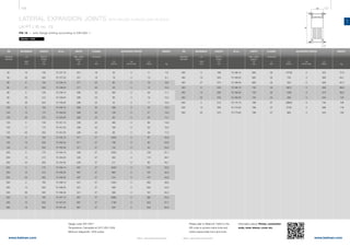
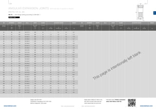
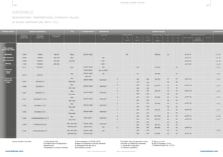
LA
B022016-1 – Subject to alterations and eventual misprintsB022016-1 – Subject to alterations and eventual misprints
On request
Please contact us, if you have any
special requirements for
eg. temperature down to -60°C,
a special combination of ends etc.
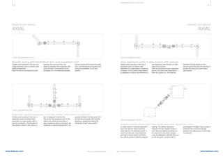
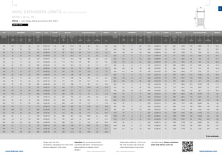
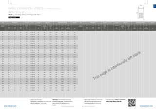
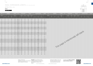
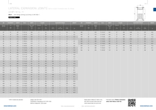
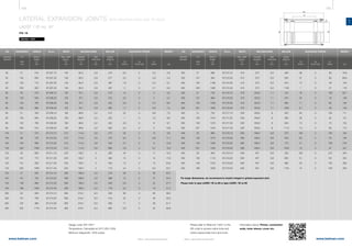
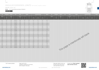
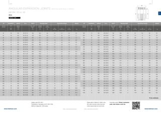
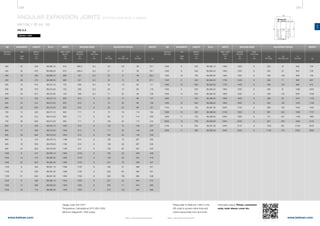
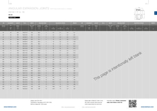
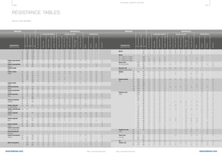
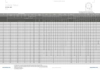
Design condition
l Design code: EN 14917
l Designed at 20°C for minimum
1000 thermal load cycles
l Arranged according nominal
pressure [PN]
l PN corresponds to the allowable
operating pressure at room
temperature [Rpt]
l Operating temperature from
-10°C to +400°C based on the
reduction factor (Kpa) from the
table on the next page
l All expansion joints are designed
to be tested at a pressure 1,43 x
the design pressure.
Where a higher test pressure is
required a unit with a higher
nominal pressure (PN) should be
selected to achieve this
Accessories
Inner sleeve, cover, counter flange,
gaskets, insulation etc. are available
on request.
Certificates
Material certificate 3.1 according to
EN 10204 and/or ASME.
Bellow
Multiply bellow in double certified
material.
Material: EN 1.4541/AISI 321 or
EN 1.4571/AISI 316 Ti
Tolerances: according to
EN ISO 13920 Class C.
Connection ends
Flanges
Loose flanges, welded flanges.
Drilling according to EN 1092.
Material: 1.0460 (C 22.8) or
1.0425 P265 GH (HII)
Surface treatment: primer coated.
Stainless steel flanges are
available on request.
Tolerances: according to norms and
standards that applies.
Welding ends
Material:
≤ DN 500: EN 1.0345/P235 GH (HI)
> DN 500: EN 1.0425/P265 GH (HII)
Surface treatment: primer coated.
Stainless steel welding ends are
available on request.
Tolerances: according to norms and
standards that applies.
Tie rods
Material: 1.7225 (42CrMo4)
The design of the tie rods and the
number of them are determined by
diameter and pressure.
Attachment plates and lugs
Material: EN 1.0425/P265 GH (HII)
STANDARD RANGE
DESIGN
We are specialised in designing and
manufacturing of customised
solutions. See selected examples
here: WebLink 13601
If the required/specified expansion
joint is not found in this product
catalogue, please do not hesitate to
forward your specifications to us.
CUSTOMISED
SOLUTIONS
PLEASE NOTE!
Vibrations
There are many ways to absorb
vibration. To know more about it,
please contact us.
Misalignment
We strongly advise against the use of
expansion joints and bellows for
misalignment.
Torsion
Torsion on bellow parts are not
desirable and should be set to zero (0).
If this cannot be avoided, please
contact us.
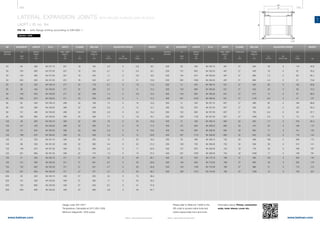
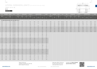
TEMPERATURE
°C
REDUCTION FACTOR
Kpa
20 1,00
100 0,83
150 0,78
200 0,74
250 0,71
300 0,67
350 0,64
400 0,62
Pressure reduction factor
The factor used for reduction of
pressure [Kpa], is based on the bellow
material yield strength at design
temperature [Rp], and the yield
strength at room temperature [Rpt].
Definiton: Kpa = Rp / Rpt
The reduction factor is applied to
modify the design pressure [PS] where
temperatures exceed 20°C, it com-
pensates for the decay in material
mechanical properties at elevated
temperatures.The modified pressure
must always be lower than the
nominal pressure of the standard item.
Calculation: PS / Kpa ≤ PN
Where the applied design pressure
is lower than the nominal pressure
for the standard unit an increase in
fatigue life expectancy and / or
increased movements can be
achieved.
Please refer to Belmaker Light®
to get an optimised solution.](https://image.slidesharecdn.com/belman-expansionjointcatalogueukreducedsize-160623085016/85/Expansion-Joint-Catalogue-75-320.jpg)


![238 239
www.belman.comwww.belman.com
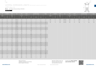
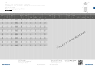
AN
B022016-1 – Subject to alterations and eventual misprintsB022016-1 – Subject to alterations and eventual misprints
On request
Please contact us, if you have any
special requirements for
eg. temperature down to -60°C,
a special combination of ends etc.
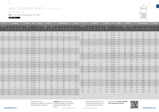
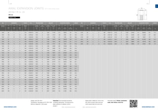
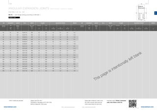
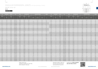
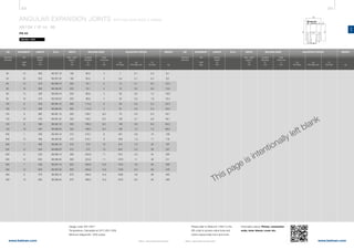
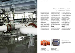
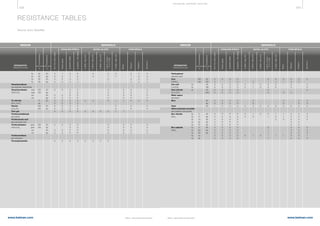
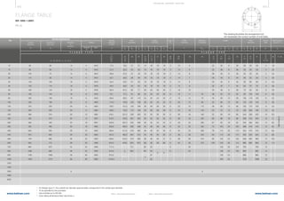
Design condition
l Design code: EN 14917
l Designed at 20°C for minimum
1000 thermal load cycles
l Arranged according nominal
pressure [PN]
l PN corresponds to the allowable
operating pressure at room
temperature [Rpt]
l Operating temperature from
-10°C to +400°C based on the
reduction factor (Kpa) from the
table on the next page
l All expansion joints are designed
to be tested at a pressure 1,43 x
the design pressure.
Where a higher test pressure is
required a unit with a higher
nominal pressure (PN) should be
selected to achieve this
Accessories
Inner sleeve, cover, counter flange,
gaskets, insulation etc. are available
on request.
Certificates
Material certificate 3.1 according to
EN 10204 and/or ASME.
Bellow
Multiply bellow in double certified
material.
Material: EN 1.4541/AISI 321 or
EN 1.4571/AISI 316 Ti
Tolerances: according to
EN ISO 13920 Class C.
Connection ends
Flanges
Loose flanges, welded flanges.
Drilling according to EN 1092.
Material: 1.0460 (C 22.8) or
1.0425 P265 GH (HII)
Surface treatment: primer coated.
Stainless steel flanges are
available on request.
Tolerances: according to norms and
standards that applies.
Welding ends
Material:
≤ DN 500: EN 1.0345/P235 GH (HI)
> DN 500: EN 1.0425/P265 GH (HII)
Surface treatment: primer coated.
Stainless steel welding ends are
available on request.
Tolerances: according to norms and
standards that applies.
Attachment plates/hinges/gimbals
Material: EN 1.0425/P265 GH (HII)
STANDARD RANGE
DESIGN
We are specialised in designing and
manufacturing of customised
solutions. See selected examples
here: WebLink 13601
If the required/specified expansion
joint is not found in this product
catalogue, please do not hesitate to
forward your specifications to us.
CUSTOMISED
SOLUTIONS
PLEASE NOTE!
Vibrations
There are many ways to absorb
vibration. To know more about it,
please contact us.
Misalignment
We strongly advise against the use of
expansion joints and bellows for
misalignment.
Torsion
Torsion on bellow parts are not
desirable and should be set to zero (0).
If this cannot be avoided, please
contact us.
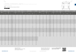
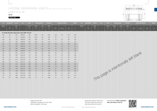
TEMPERATURE
°C
REDUCTION FACTOR
Kpa
20 1,00
100 0,83
150 0,78
200 0,74
250 0,71
300 0,67
350 0,64
400 0,62
Pressure reduction factor
The factor used for reduction of
pressure [Kpa], is based on the bellow
material yield strength at design
temperature [Rp], and the yield
strength at room temperature [Rpt].
Definiton: Kpa = Rp / Rpt
The reduction factor is applied to
modify the design pressure [PS] where
temperatures exceed 20°C, it com-
pensates for the decay in material
mechanical properties at elevated
temperatures. The modified pressure
must always be lower than the nominal
pressure of the standard item.
Calculation: PS / Kpa ≤ PN
Where the applied design pressure
is lower than the nominal pressure
for the standard unit an increase in
fatigue life expectancy and / or
increased movements can be
achieved.
Please refer to Belmaker Light®
to get an optimised solution.](https://image.slidesharecdn.com/belman-expansionjointcatalogueukreducedsize-160623085016/85/Expansion-Joint-Catalogue-122-320.jpg)


![310 311
www.belman.comwww.belman.com
UN
B022016-1 – Subject to alterations and eventual misprintsB022016-1 – Subject to alterations and eventual misprints
On request
Please contact us, if you have any
special requirements for
eg. temperature down to -60°C,
a special combination of ends etc.
Design condition
l Design code: EN 14917
l Designed at 20°C for minimum
1000 thermal load cycles
l Arranged according nominal
pressure [PN]
l PN corresponds to the allowable
operating pressure at room
temperature [Rpt]
l Operating temperature from
-10°C to +400°C based on the
reduction factor (Kpa) from the
table on the next page
l All expansion joints are designed
to be tested at a pressure 1,43 x
the design pressure.
Where a higher test pressure is
required a unit with a higher
nominal pressure (PN) should be
selected to achieve this
Movements
Movements are considered alternatives.
The total accumulated coefficient of
utilisation cannot exceed 1.
A 100% AX utilisation allows no lateral
movements.
Bellow
Multiply bellow in double certified
material.
Material: EN 1.4541/AISI 321 or
EN 1.4571/AISI 316 Ti
Tolerances: according to
EN ISO 13920 Class C.
Connection ends
Flanges
Loose flanges, welded flanges.
Drilling according to EN 1092.
Material: 1.0460 (C 22.8) or
1.0425 P265 GH (HII)
Surface treatment: primer coated.
Stainless steel flanges are
available on request.
Tolerances: according to norms and
standards that applies.
Welding ends
Material:
≤ DN 500: EN 1.0345/P235 GH (HI)
> DN 500: EN 1.0425/P265 GH (HII)
Surface treatment: primer coated.
Stainless steel welding ends are
available on request.
Tolerances: according to norms and
standards that applies.
STANDARD RANGE
DESIGN
We are specialised in designing and
manufacturing of customised
solutions. See selected examples
here: WebLink 13601
If the required/specified expansion
joint is not found in this product
catalogue, please do not hesitate to
forward your specifications to us.
CUSTOMISED
SOLUTIONS
Accessories
Inner sleeve, cover, counter flange,
gaskets, insulation etc. are available
on request.
Certificates
Material certificate 3.1 according to
EN 10204 and/or ASME.
PLEASE NOTE!
Vibrations
There are many ways to absorb
vibration. To know more about it,
please contact us.
Misalignment
We strongly advise against the use of
expansion joints and bellows for
misalignment.
Torsion
Torsion on bellow parts are not
desirable and should be set to zero (0).
If this cannot be avoided, please
contact us.
TEMPERATURE
°C
REDUCTION FACTOR
Kpa
20 1,00
100 0,83
150 0,78
200 0,74
250 0,71
300 0,67
350 0,64
400 0,62
Pressure reduction factor
The factor used for reduction of
pressure [Kpa], is based on the bellow
material yield strength at design
temperature [Rp], and the yield
strength at room temperature [Rpt].
Definiton: Kpa = Rp / Rpt
The reduction factor is applied to
modify the design pressure [PS] where
temperatures exceed 20°C, it com-
pensates for the decay in material
mechanical properties at elevated
temperatures. The modified pressure
must always be lower than the nominal
pressure of the standard item.
Calculation: PS / Kpa ≤ PN
Where the applied design pressure
is lower than the nominal pressure
for the standard unit an increase in
fatigue life expectancy and / or
increased movements can be
achieved.
Please refer to Belmaker Light®
to get an optimised solution.](https://image.slidesharecdn.com/belman-expansionjointcatalogueukreducedsize-160623085016/85/Expansion-Joint-Catalogue-158-320.jpg)


![350 351
www.belman.comwww.belman.com
VA
B022016-1 – Subject to alterations and eventual misprintsB022016-1 – Subject to alterations and eventual misprints
On request
Please contact us, if you have any
special requirements for
eg. temperature down to -60°C,
a special combination of ends etc.
Design condition
l Design code: EN 14917
l Designed at 20°C for minimum
1000 thermal load cycles (2λN) and
vibrations (+/- 0,5 mm in all
planes).
l Arranged according nominal
pressure [PN]
l PN corresponds to the allowable
operating pressure at room
temperature [Rpt]
l Operating temperature from
-10°C to +400°C based on the
reduction factor (Kpa) from the
table on the next page
l All expansion joints are designed
to be tested at a pressure 1,43 x
the design pressure.
Where a higher test pressure is
required a unit with a higher
nominal pressure (PN) should be
selected to achieve this
Bellow
Multiply bellow in double certified
material.
Material: EN 1.4541/AISI 321 or
EN 1.4571/AISI 316 Ti
Tolerances: according to
EN ISO 13920 Class C.
Connection ends
Flanges
Welded flanges.
Drilling according to EN 1092.
Material: 1.0460 (C 22.8) or
1.0425 P265 GH (HII)
Surface treatment: primer coated.
Stainless steel flanges are
available on request.
Tolerances: according to norms and
standards that applies.
Tie rods
Material: 1.7225 (42CrMo4)
The design of the tie rods and the
number of them are determined by
diameter and pressure.
Rubber bushes: NBR (to max. 120ºC,
at higher temperatures metallic
springs are used).
STANDARD RANGE
DESIGN
We are specialised in designing and
manufacturing of customised
solutions. See selected examples
here: WebLink 13601
If the required/specified expansion
joint is not found in this product
catalogue, please do not hesitate to
forward your specifications to us.
CUSTOMISED
SOLUTIONS
Accessories
Inner sleeve, cover, counter flange,
gaskets, insulation etc. are available
on request.
Certificates
Material certificate 3.1 according to
EN 10204 and/or ASME.
PLEASE NOTE!
Natural frequencies
To avoid resonant response, following
relation between the bellows natural
frequency (fn) and system frequency
(fs) must be fulfilled:
fn < 2/3 x fs
or
fn > 2 x fs
Misalignment
We strongly advise against the use of
expansion joints and bellows for
misalignment.
Torsion
Torsion on bellow parts are not
desirable and should be set to zero (0).
If this cannot be avoided, please
contact us.
TEMPERATURE
°C
REDUCTION FACTOR
Kpa
20 1,00
100 0,83
150 0,78
200 0,74
250 0,71
300 0,67
350 0,64
400 0,62
Pressure reduction factor
The factor used for reduction of
pressure [Kpa], is based on the bellow
material yield strength at design
temperature [Rp], and the yield
strength at room temperature [Rpt].
Definiton: Kpa = Rp / Rpt
The reduction factor is applied to
modify the design pressure [PS] where
temperatures exceed 20°C, it com-
pensates for the decay in material
mechanical properties at elevated
temperatures. The modified pressure
must always be lower than the nominal
pressure of the standard item.
Calculation: PS / Kpa ≤ PN
Where the applied design pressure
is lower than the nominal pressure
for the standard unit an increase in
fatigue life expectancy and / or
increased movements can be
achieved.
Please refer to Belmaker Light®
to get an optimised solution.](https://image.slidesharecdn.com/belman-expansionjointcatalogueukreducedsize-160623085016/85/Expansion-Joint-Catalogue-178-320.jpg)


![414 415
www.belman.comwww.belman.com B022016-1 – Subject to alterations and eventual misprintsB022016-1 – Subject to alterations and eventual misprints
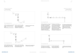
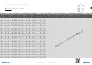
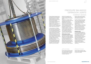
TE CHNI CA L I NFOR MATI ON
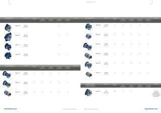
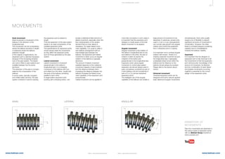
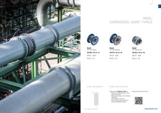
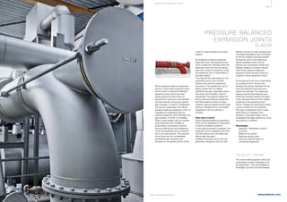
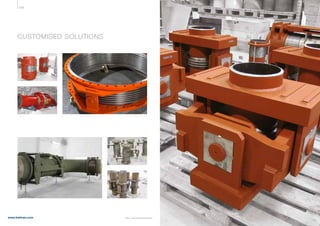
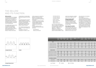
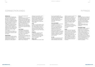
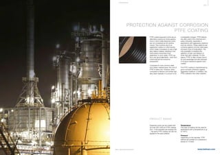
PRESSURE THRUST
Force in a perpendicular direction or
applied normally on an area is called
thrust. Pressure thrust force is the
most essential force encountered in
pressurised pipe systems and if
ignored or incorrectly calculated, it
can have a major impact on the pipe
system or the surrounding hardware.
Expansion joints are intended to
absorb pipe expansion and to
withstand pressure forces and
movements. However unrestrained
expansion joints also transfer forces,
where the most important factors are
the bellows spring rate and pressure
thrust. Pressure thrust force acts
Fp = P x A
Where:
Fp = Pressure thrust force [N]
P = Pressure [bar]
A = Bellows mean diameter
area [mm2
]
Unrestrained
With unrestrained expansion joints,
both spring rates and pressure thrust
forces occur, and the pressure thrust
is often greater than the spring rates.
This type of expansion joint always
requires fix points or a foundation,
which is rigid enough to carry the
differently depending on whether the
pipe system is anchored and guided
or floating. If unrestrained axial
expansion joints are used, pressure
thrust force must be obtained at both
ends of the pipe system by fix points.
Single bellows subjected to an axial
movement could be simplified as an
hydraulic cylinder with a spring inside.
The spring represents the axial spring
rate of the bellows, and the hydraulic
piston represents the effect of the
pressure thrust which the expansion
joint can exert on the piping fix points
or pressure thrust restraints.
The area of the hydraulic cylinder
loads. This often results in a high
financial cost.
Restrained
Alternatively, the reaction force from
the bellows can be eliminated by
using restrained expansion joints.
Restrained expansion joints are
restrained by using tie-rods, hinge- or
gimbal systems over the flexible part.
This hardware obtains all pressure
thrust forces and makes the
expansion joint behave like a straight
pipe, the only load to consider is the
spring rate.
Restrained expansion joints can be a
very cost effective solution in many
would be effective area of the bellows.
Expansion joints normally have a
cross-sectional area, which is slightly
larger than the pipe diameter due to the
height of the convolutions. This is a
critical detail to take into consideration
when designing pipe systems and fix
points. The effective cross section can
be illustrated by the sketch below.
Pressure thrust force is calculated by
the product of the bellows mean
diameter multiplied by the maximum
line pressure as follows:
(always base the calculation on the
maximum pressure that occurs, usually
the test pressure)
situations, where costly fix points and
foundation work is required.
Pressure balanced
Where large diameters, high pressure,
or fix points are impractical due to
economic or structural reasons, a
pressure balanced expansion joint
can be a powerful solution to a
challenging design problem.
This type of expansion joint is
basically the same as a restrained
unit, but in which the pressure thrust
is compensated by larger balancing
bellows or a balancing chamber.
Bellowsmeandiameter
P
Bellows effective area
P P
Fp Fp
Bellows spring rate
Hydraulic pistonCompensator pipe end
Compensator pipe end
Hydraulic cylinder
Bellows
Bellowsmeandiameter
Bellows pressure thrustBellows pressure thrust](https://image.slidesharecdn.com/belman-expansionjointcatalogueukreducedsize-160623085016/85/Expansion-Joint-Catalogue-210-320.jpg)
![416 417
www.belman.comwww.belman.com
Δx
X
F
K
B022016-1 – Subject to alterations and eventual misprintsB022016-1 – Subject to alterations and eventual misprints
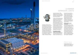
SPRING RATES
Flexible bellows can be compared to
a steel spring in its flexible motion.
The spring rate is an expression of the
force required to compress or extend
the bellows, or alternately its
resistance to deflect, which is another
factor to take into account when
calculating loads on fix points.
The bellows spring rate depends
particularly on the bellows geometry
and especially the bellows ply
thickness, the number of plies,
convolution geometry and materials.
Secondly, the actual working
temperature of the bellows also
influences the spring rate, as the steel
loses its rigidity at elevated tempera-
tures. Therefore, the specified design
temperature should be as close to the
maximum as possible, without being
overstated.
The magnitude of the spring force is
determined by the expansion joint
spring constant and the amount of
movement of the expansion joint,
which is calculated as follows:
F = K x X
Where:
F = Force [N]
K = Spring rate [N/mm]
X = Movement [mm]
The bellows will have a spring back
effect when the movement range is
within the elastic range of the
material. But an excessive movement
range will result in a permanent
deformation of the bellows, especially
when the movement range is entering
into the plastic range of the bellows
material.
Belman specifies spring rates
calculated in full in accordance with
the specified code. The majority of
tests have verified actual spring rates
to have been around 30% less than
calculated. When a particular
application requires a more precise
specification of the bellows working
spring rate, the customer should
specify this to Belman. In special
projects, Belman will determine if a
prototype testing is necessary to
specify the precise load vs. deflection
characteristics of a particular bellows
design.
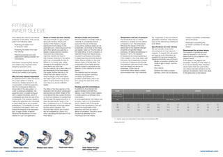
STABILITY
Expansion joints have to be flexible to
absorb movements but at the same
time they require the strength and
stability to transfer any specified fluid
at a given pressure and temperature.
In case an expansion joint is exposed
to an excessive internal pressure, the
bellows will show instability. Instability
can occur in two modes, column
instability or in-plane deformation
(squirm) of the convolution side wall.
Column instability applies only to
bellows with internal pressure.
Column instability (or squirm) is the
phenomena whereby the centerline of
a straight bellows develops a side-
ways or lateral bow. Column instability
affects the bellows as a whole, while
in-plane or squirm deformation affects
only one or more convolutions
individually. In-plane instability, called
also local instability or squirm, occurs
in bellows with relative small ratio of
length and diameter, and is defined as
slipping or twisting the plane of one or
several convolutions against each
parallel convolution.
The critical pressure at which this
instability occurs is a direct function of
the diameter and spring rate, and an
inverse function of the length.
A simple way to imagine this, is to
remember that the bellow is a cylinder
of given volume. Internal pressure
tries to increase a vessel’s volume.
Since a bellow is flexible in the axial
direction, it can increase its volume by
increasing the length of its centerline.
With the ends fixed, it tries so by
simulating the appearance of a
buckling column.
Column instability In-plane instability
TE CHNI CA L I NFOR MATI ON](https://image.slidesharecdn.com/belman-expansionjointcatalogueukreducedsize-160623085016/85/Expansion-Joint-Catalogue-211-320.jpg)


![480 481
www.belman.comwww.belman.com B022016-1 – Subject to alterations and eventual misprintsB022016-1 – Subject to alterations and eventual misprints
10 mm
thickness,
transverse min.
KV in J
min. KV
J
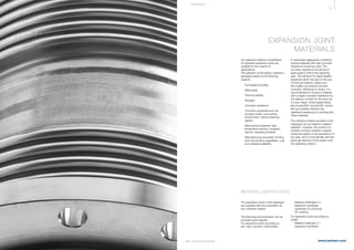
NON-ALLOYED
COMMON
STRUCTURAL STEEL
HEAT RESISTANT
NON-ALLOYED
HEAT RESISTANT
STEEL
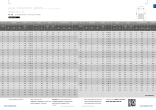
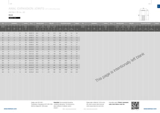
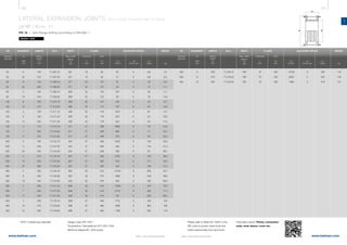
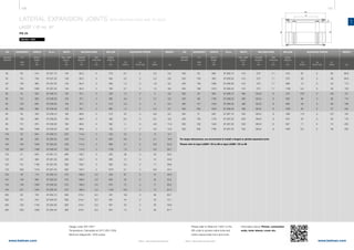
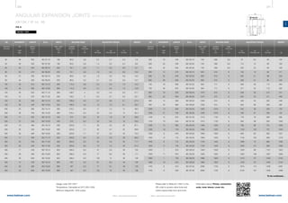
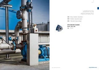
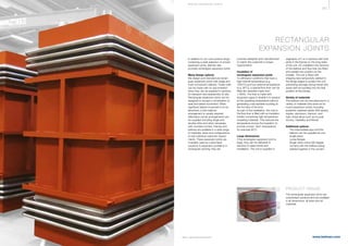
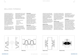
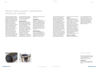
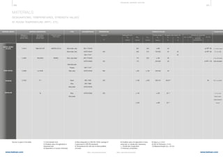
MATERIALS
DESIGNATIONS, TEMPERATURES, STRENGTH VALUES
AT ROOM TEMPERATURE (R PT) , ETC.
Source: Is given in the table.
MATERIAL GROUP MATERIAL DESIGNATION TYPE DOCUMENTATION
Material no.
according to
DIN EN 10027
Common known
short name
Short name
according to
DIN EN 10027
min. Av
, (KV4)
)
J
TEMPERATURE
Upper limit
o
C
Yield point min.
Tensile strength
Rm
N/mm2
STRENGTH VALUES
A5
%
A80
%
1.0254
1.0255
1.0427
1.0038
1.0050
1.0570
1.0460
1.0345
1.0425
1.0481
1.5415
1.7335
1.7380
1.0305
P235TR1
P235TR2
C22G1
S235JRG2
E295
S355J2G3
C22G2
P235GH
P265GH
P295GH
16Mo3
13CrMo4-5
10CrMo9-10
P235G1TH
St. 37.0
St. 37.4
C 22.3
RSt 37-2
St 50-2
St 52-3
C 22.8
HI
HII
17 Mn 4
15 Mo 3
13 CrMo 4 4
10 CrMo 9 10
St. 35.8
DIN EN 10217-1
DIN EN 10216-1
DIN EN 10217-1
DIN EN 10216-1
VdTÜV-W 364
DIN EN 10025
ADW1
VdTÜVW 350
DIN EN 10028
DIN EN 10216
DIN EN 10028
DIN EN 10028
DIN 17175
DIN EN 10028
DIN 17175
DIN EN 10028
DIN 17175
DIN EN 10028
DIN 17175
DIN 17175
300
350
300
450
480
450
480
500
530
570
600
480
235
235
240
235
295
355
240
235
235
265
295
270
275
270
300
290
310
280
235
360-500
360-500
410-540
340-470
470-610
490-630
410-540
360-480
360-500
410-530
460-580
440-590
440-600
480-630
360-480
23
23
20 (transverse)
21-26 1)
16-20 1)
18-22 1)
20
25
23
23
22
24
20
18
23
17-21 3)
12-16 3)
14-18 )
at 0°C: 27
at RPT: 31
at RPT: 27
at -20°C: 27
at RPT:31
at 0°C: 27
at 0°C: 27
at 0°C: 27
at 0°C: 27
at RPT:31
at RPT:31
at RPT:31
at RPT:34
Welded pipe
Seamless pipe
Welded pipe
Seamless pipe
Flanges
Steel bar, flat products,
wire rod
profiles
Flanges
Sheet
Seamless pipe
Sheet
Sheet
Seamless pipe
Sheet
Seamless pipe
Sheet
Seamless pipe
Sheet
Seamless pipe
Seamless pipe
Elongation after fraction min.
ReH
N/mm2
Rp0,2
N/mm2
Rp1,0
N/mm2
Notched bar impact strength
1) Cold resistant limit
2) Smallest value of longitudinal or
transverse test
3) Dependent on product thickness
4) New designation to DIN EN 10045;
average of 3 specimens in DIN EN standards
5) Temperature limit with risk of
intercrystalline corrosion
6) Smallest value of longitudinal or trans-
verse test, q= tensile test, transverse,
I = Tensile test, longitudinal
7) Chemical composition
s ≤ 16
s ≤ 16
s ≤ 70
3 ≤ s ≤100 (Rm
)
10 ≤ s ≤150 (KV)
s ≤ 16 (ReH
)
s ≤ 670
s ≤ 16
s ≤ 16
s ≤ 16
s ≤ 16
s ≤ 16
s ≤ 16
s ≤ 16
s ≤ 16
PLEASE NOTE
8) Value ak
in J/cm2
9) A50 for thickness ≤ 5 mm
10) Measured length (Lo) = 25 mm
STEEL
STEEL
TE CHNI CA L S U P P ORT S E CTI ON [R pt ]](https://image.slidesharecdn.com/belman-expansionjointcatalogueukreducedsize-160623085016/85/Expansion-Joint-Catalogue-243-320.jpg)


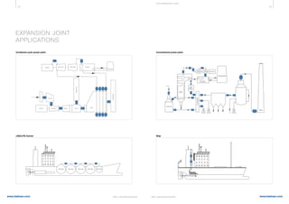
The Belman expansion joints catalogue provides comprehensive information on various types of metallic expansion joints, including their applications across industries, technical specifications, and design guidelines. The catalogue emphasizes the advantages of using expansion joints over alternatives such as pipe loops, highlighting cost-effectiveness, space savings, and reduced maintenance needs. Additionally, it offers access to customized solutions and technical support through the company's website.


![[Point] pipe stress analysis by computer-caesar ii](https://cdn.slidesharecdn.com/ss_thumbnails/point-pipestressanalysisbycomputer-caesarii-150407122607-conversion-gate01-thumbnail.jpg?width=640&height=640&fit=bounds)


