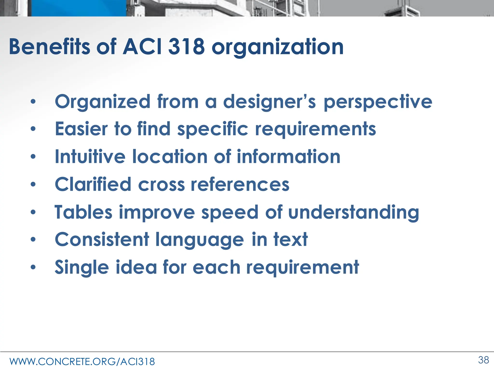
This document provides information about a seminar on changes to the ACI 318 concrete design standard from ACI 318-14 to ACI 318-19. The seminar will cover major changes grouped by topic, including changes to requirements for high-strength reinforcement, development lengths, shear design, durability, shotcrete, and appendix A. Attendees will learn about the new organization of ACI 318-19 and how it is designed to make information easier to find. The seminar will also discuss provisions for evaluating existing concrete structures and changes to load and analysis requirements.


-(3”)(7.5”)
= 805 in.2
32 in.
32 in.
3 in.
22.9 in.
ca1 =
15.25 in.
V](https://image.slidesharecdn.com/aci318-19presentation-240229104905-92f0123c/75/ACI-318-19-Presentation-changes-to-the-concrete-design-standard-167-2048.jpg)


![WWW.CONCRETE.ORG/ACI318 183
18.4.3.3—Columns in intermediate moment
frames
• Hoops or spirals required
• First hoop at so/2 from the joint
face
o
ℓu /6 clear span
[c1, c2]max
18 in.
so
ℓo
ℓo
8db (Gr 60) and 8 in.
6db (Gr 80) and 6 in.
1/2[c1, c2]min
so ≤
ℓo ≥](https://image.slidesharecdn.com/aci318-19presentation-240229104905-92f0123c/75/ACI-318-19-Presentation-changes-to-the-concrete-design-standard-183-2048.jpg)


![WWW.CONCRETE.ORG/ACI318 186
18.7.5.3 and 18.7.5.5—Columns in special
moment frames
• First hoop at so/2 from the
joint face
so
ℓo
ℓu/6 clear span
[c1, c2]max
18 in.
s
6db,min (Gr 60), 5db,min (Gr 80)
6 in.
ℓo
so
6db,min (Gr 60), 5db,min (Gr 80)
¼[c1, c2]min
4 +
14−ℎ𝑥
3
, ≤ 6 in.; ≥ 4 in.
ℓo ≥
s ≤
so ≤](https://image.slidesharecdn.com/aci318-19presentation-240229104905-92f0123c/75/ACI-318-19-Presentation-changes-to-the-concrete-design-standard-186-2048.jpg)


![WWW.CONCRETE.ORG/ACI318 200
18.10.3—Shear amplification
18.10.3.1.2 – Calculation of Ωv
Table 18.10.3.1.2—Overstrengthfactor Ωv at critical section
[1] For the load combination producing the largest value of Ωv.
[2] Unless a more detailed analysis demonstrated a smaller value,
but not less than 1.0.
Condition Ωv
hwcs/ℓw > 1.5 Greater of
Mpr/Mu
[1]
1.5[2]
hwcs/ℓw ≤ 1.5 1.0](https://image.slidesharecdn.com/aci318-19presentation-240229104905-92f0123c/75/ACI-318-19-Presentation-changes-to-the-concrete-design-standard-200-2048.jpg)


![WWW.CONCRETE.ORG/ACI318 205
18.10.6.2—Displacement based approach
(a) Compression zone with
special boundary elements
required if:
• c = [Pu, fMn]max in direction of
design displacement du and
• du/hwcs ≥ 0.005
1.5
600
u w
wcs
h c
d
Single critical section
hwcs
du
Extreme
compression fiber](https://image.slidesharecdn.com/aci318-19presentation-240229104905-92f0123c/75/ACI-318-19-Presentation-changes-to-the-concrete-design-standard-205-2048.jpg)
![WWW.CONCRETE.ORG/ACI318 206
18.10.6.2—Displacement based approach
(b) Boundary elements req’d, then (i) and
either (ii) or (iii)
i. Transv. reinf. extends above and below
critical section [ℓw, Mu/4Vu]max
ii.
iii. dc/hwcs ≥ 1.5 du / hwcs , where
'
1 1
4 0.015
100 50 8
c w e
wcs c cv
c V
h b b f A
d
= − −
0.025 w
b c
Errata](https://image.slidesharecdn.com/aci318-19presentation-240229104905-92f0123c/75/ACI-318-19-Presentation-changes-to-the-concrete-design-standard-206-2048.jpg)


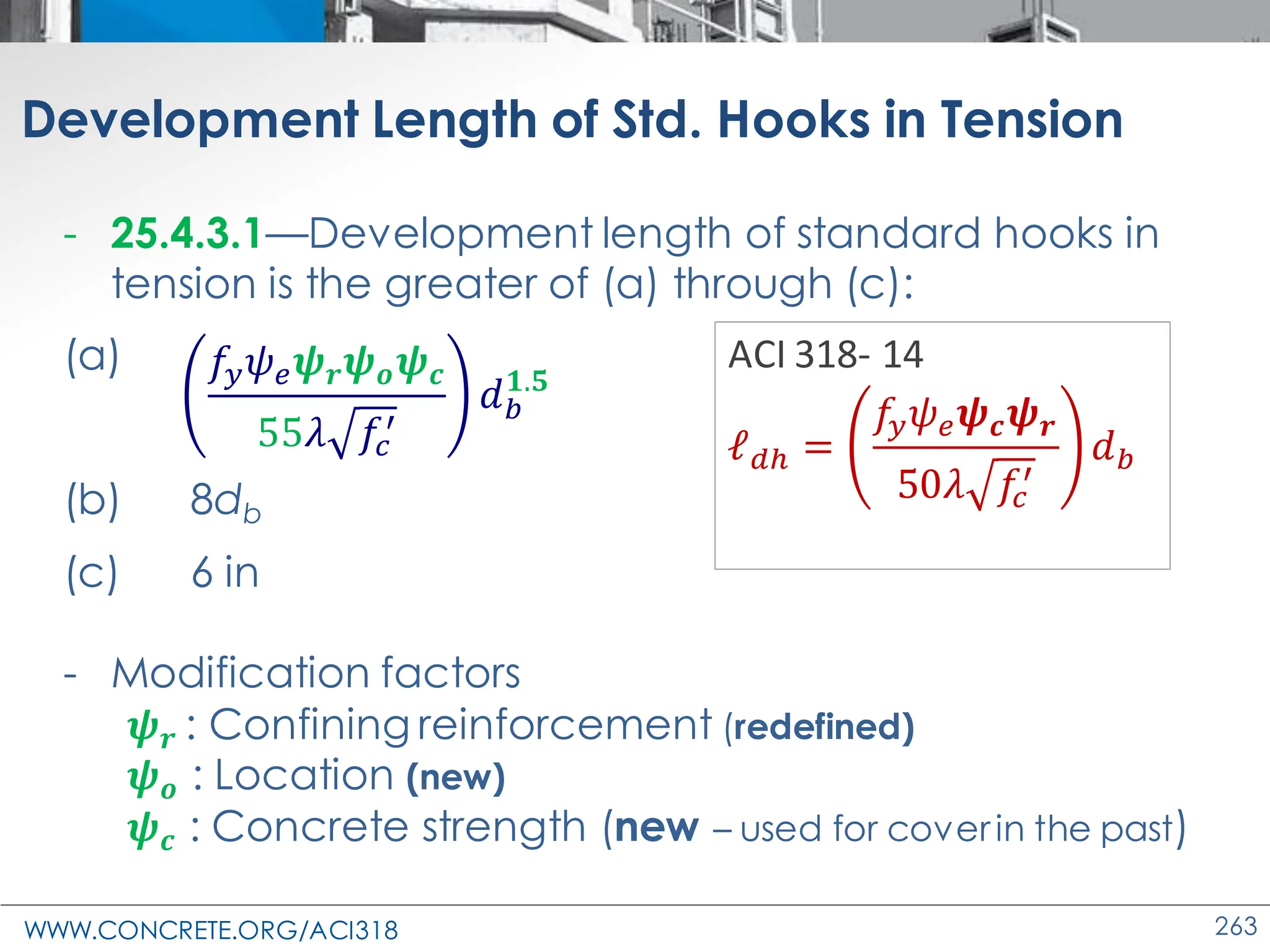
![WWW.CONCRETE.ORG/ACI318 256
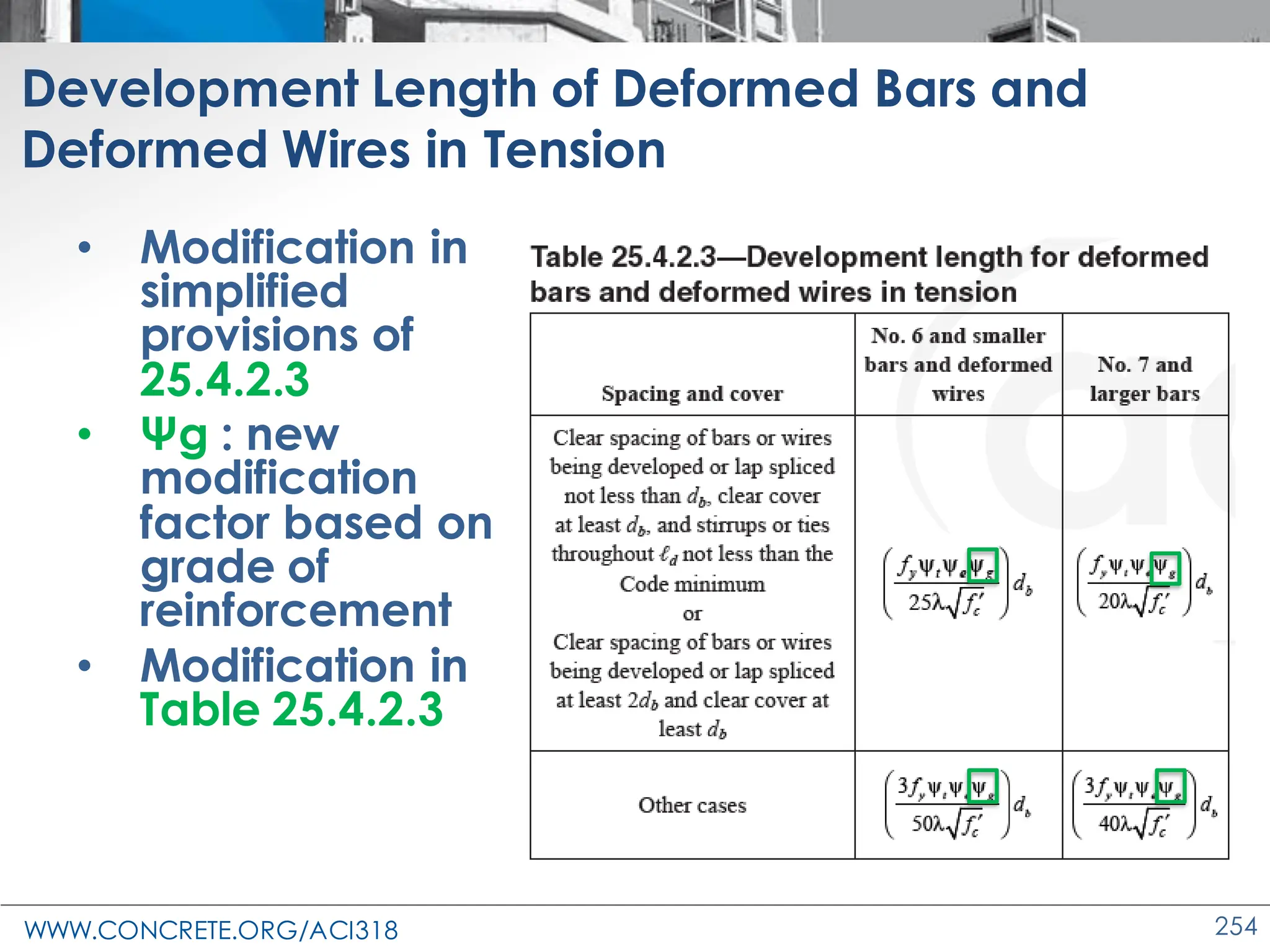
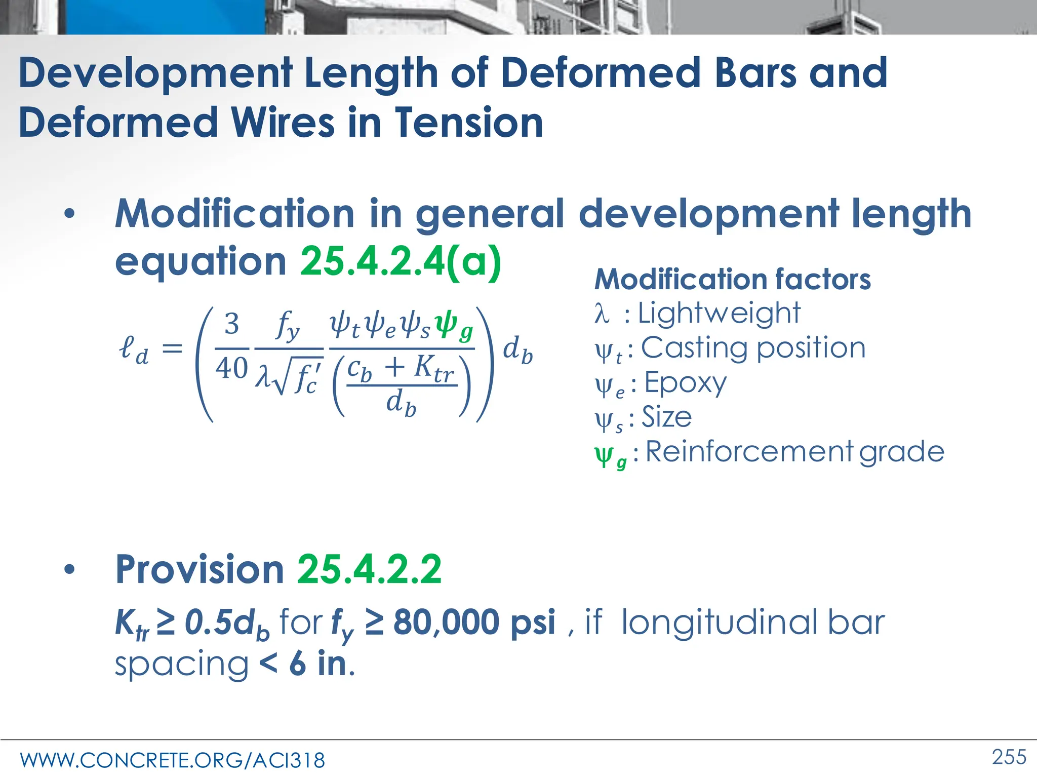
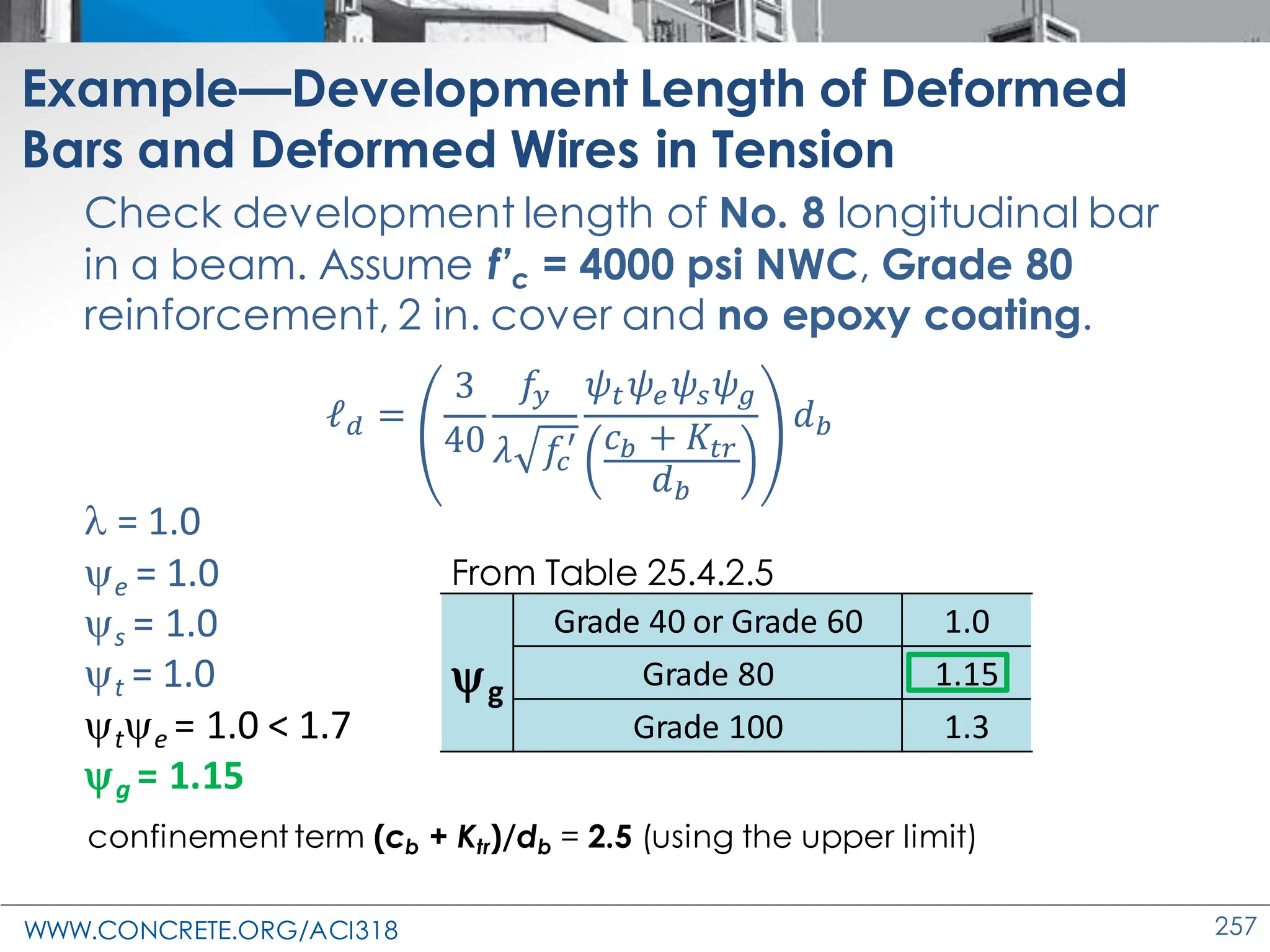
Development Length of Deformed Bars and
Deformed Wires in Tension
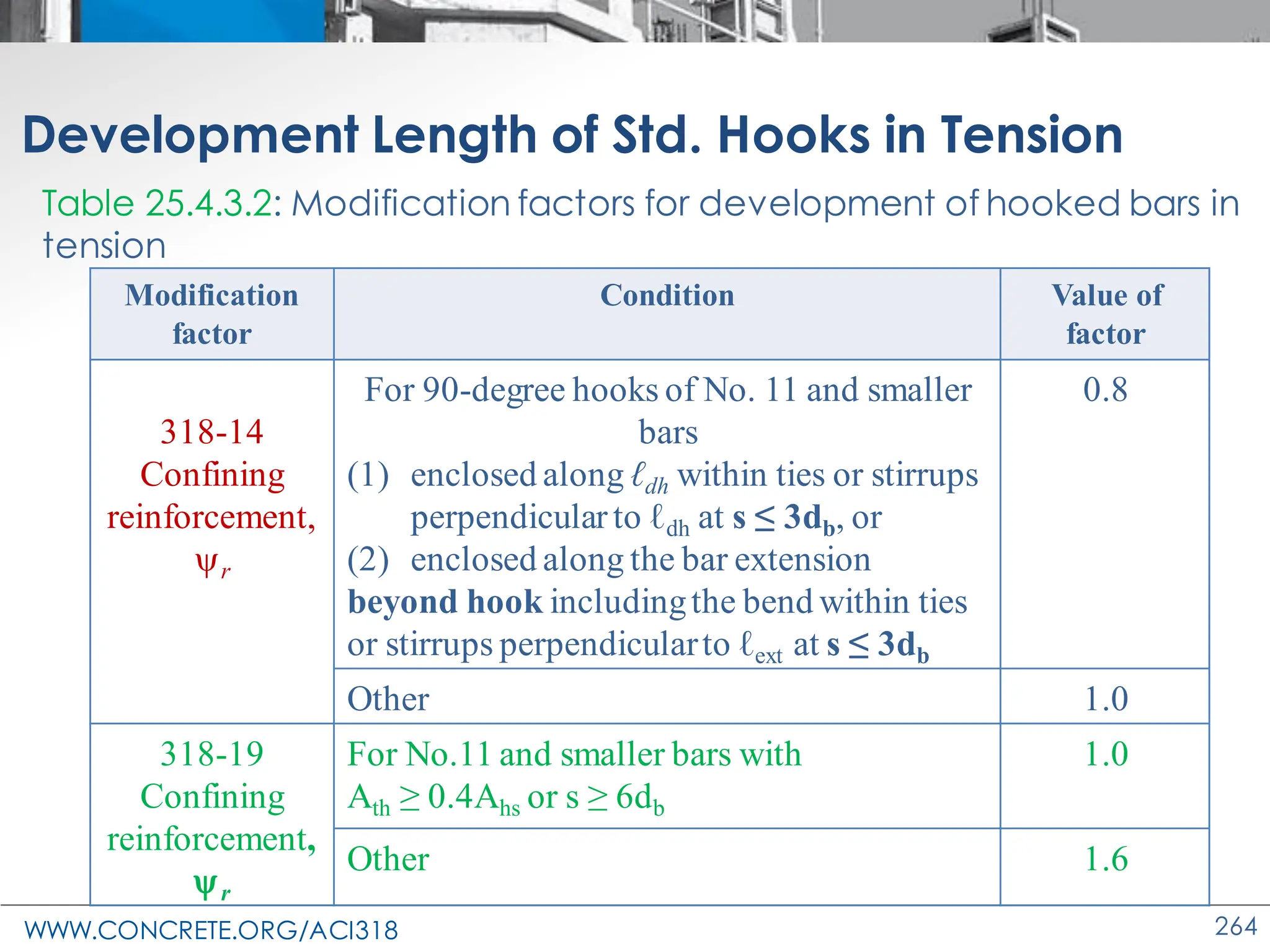
Modificationfactor Condition
Value of
factor
Lightweightλ
Lightweight concrete 0.75
Normalweightconcrete 1.0
Reinforcement
gradeg
Grade40 or Grade60 1.0
Grade80 1.15
Grade100 1.3
Epoxy[1]
e
Epoxy-coated or zinc and epoxy dual-coated reinforcement
with clear cover less than 3db or clear spacing less than 6db
1.5
Epoxy-coated or zinc and epoxy dual-coated reinforcementfor
all other conditions
1.2
Uncoated or zinc-coated (galvanized) reinforcement 1.0
Sizes
No. 7 and larger bars 1.0
No. 6 and smaller bars and deformed wires 0.8
Casting position[1]
t
More than 12 in. of fresh concreteplaced below horizontal
reinforcement
1.3
Other 1.0
Table 25.4.2.5—Modification factors for development of deformed
bars and deformed wires in tension](https://image.slidesharecdn.com/aci318-19presentation-240229104905-92f0123c/75/ACI-318-19-Presentation-changes-to-the-concrete-design-standard-256-2048.jpg)


![WWW.CONCRETE.ORG/ACI318 392
23.5 Minimum distributed reinforcement
Member Distributed reinforcement, min Spacing, s
Deep beams
(9.9.3.1 & 9.9.4.3)
≥ 0.0025 in each direction
Min. [d/5 and
12 in.]
Wall
Vu ≤ fVc/2
(11.6.1)
Longitudinal Transverse
Min. [3h, 18 in.]
(11.7.2 & 11.7.3)
CIP 0.0012 to 0.0015 0.002 to 0.0025
Precast 0.001 0.001
Vu > fVc/2
(11.6.2)
0.0025 ≥ 0.0025
ACI 318-19 – minimum distributed reinforcement
requirements in deep beams and walls](https://image.slidesharecdn.com/aci318-19presentation-240229104905-92f0123c/75/ACI-318-19-Presentation-changes-to-the-concrete-design-standard-392-2048.jpg)