Download to read offline

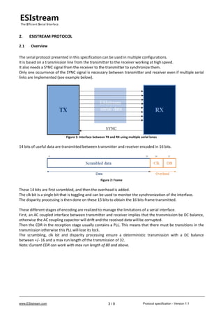
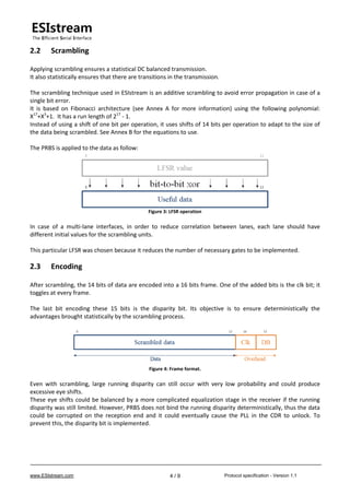
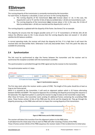
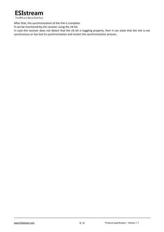
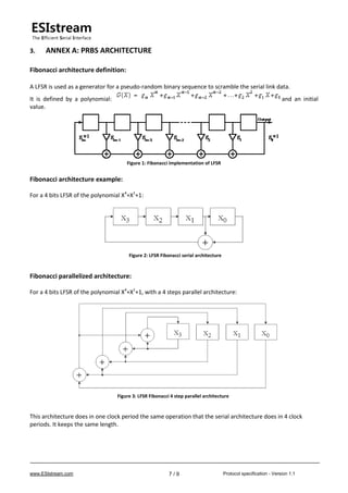
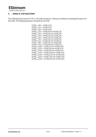
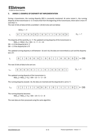

The document outlines the specification for the esistream protocol, an efficient open serial interface that utilizes 14b/16b encoding, primarily designed for high-speed data conversion systems. It details the functionalities of scrambling, encoding, synchronization, and the implementation of a disparity bit to maintain DC-balanced transmission and monitor synchronization between the transmitter and receiver. The document includes various annexes that elaborate on the protocol's architecture, equations, and examples of its implementation.


![Getting Started with Apache Spark: Big Data Made Simple [Free Meetup]](https://cdn.slidesharecdn.com/ss_thumbnails/apachesparkgettingstarted-260203175547-8361bcc3-thumbnail.jpg?width=640&height=640&fit=bounds)

