
Download as PDF, PPTX
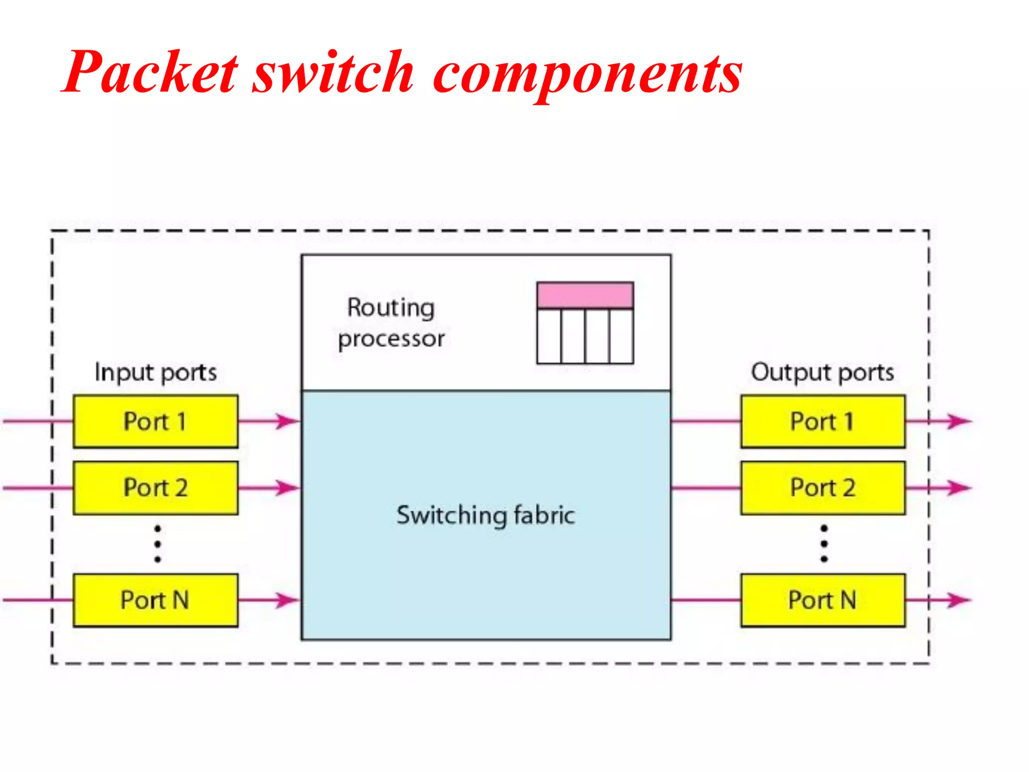

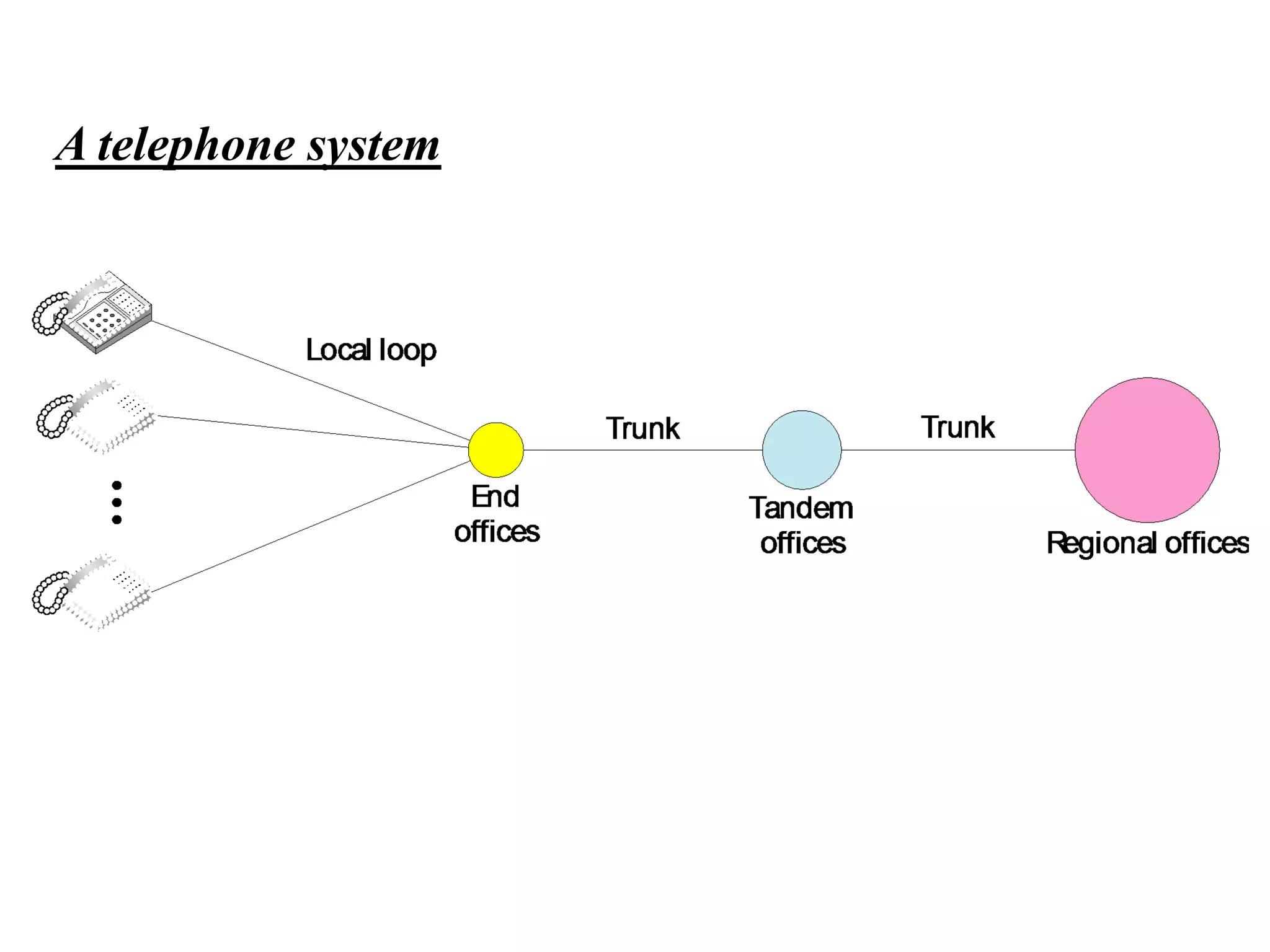
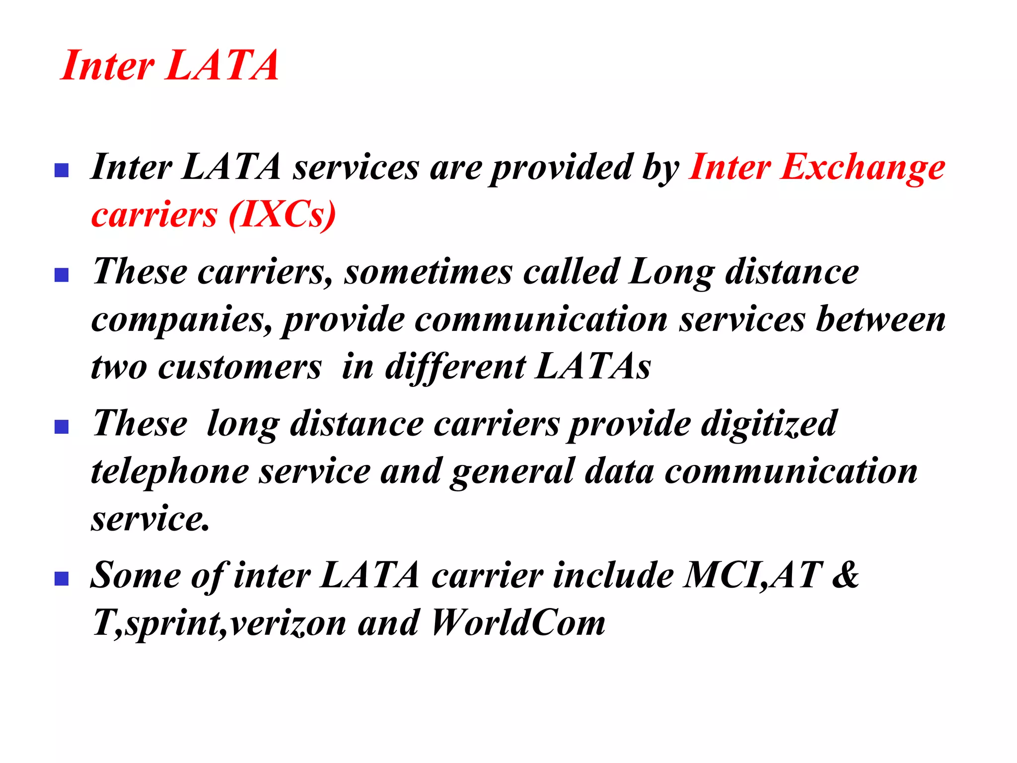

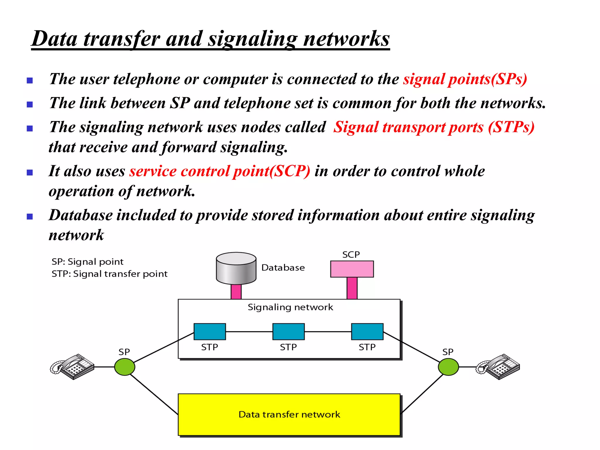

The document discusses the structure and functioning of switches in both circuit-switched and packet-switched networks. It highlights the limitations of crossbar switches and introduces multistage switches as a solution, while also detailing the components of packet switches. Additionally, it covers the historical context of telephone networks, including local loops, trunks, and switching offices, as well as the services provided within Local Access Transport Areas (LATA) and signaling methods.


![Vibe Coding vs. Spec-Driven Development [Free Meetup]](https://cdn.slidesharecdn.com/ss_thumbnails/vibecodingvsspecdrivendevelopment-251209105622-43f455e7-thumbnail.jpg?width=640&height=640&fit=bounds)


