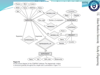
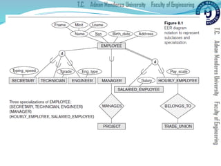
Prepared & Presented by Asst. Prof. Dr. Samsun M. BAŞARICI
CSE202 Database Management Systems
Lecture #4
2
 Apply high-level conceptual data modeling
 Creating a sample database
 Understand and apply DB terms
 Differentiate between ER and UML notations
Learning Objectives
3
 Using high-level conceptual data models for database design
 A sample database application
 Entity types, entity sets, attributes, and keys
 Relationship types, relationship sets, roles, and structural
constraints
 Weak entity types
 Refining the ER design for the COMPANY database
 ER diagrams, naming conventions, and design issues
 Example of other Notation: UML class diagrams
 Relationship types of degree higher than two
Outline
Data Modeling Using the Entity-Relationship (ER) Model
 Entity-Relationship (ER) model
 Popular high-level conceptual data model
 ER diagrams
 Diagrammatic notation associated with the ER model
 Unified Modeling Language (UML)
Using High-Level Conceptual Data Models for
Database Design
 Requirements collection and analysis
 Database designers interview prospective database users to
understand and document data requirements
 Result: data requirements
 Functional requirements of the application
Using High-Level Conceptual Data Models (cont’d.)
 Conceptual schema
 Conceptual design
 Description of data requirements
 Includes detailed descriptions of the entity types,
relationships, and constraints
 Transformed from high-level data model into
implementation data model
Using High-Level Conceptual Data Models (cont.)
 Logical design or data model mapping
 Result is a database schema in implementation data model
of DBMS
 Physical design phase
 Internal storage structures, file organizations, indexes,
access paths, and physical design parameters for the
database files specified
A Sample Database Application
 COMPANY
 Employees, departments, and projects
 Company is organized into departments
 Department controls a number of projects
 Employee: store each employee’s name, Social Security
number, address, salary, sex (gender), and birth date
 Keep track of the dependents of each employee
Entity Types, Entity Sets, Attributes, and Keys
 ER model describes data as:
 Entities
 Relationships
 Attributes
Entities and Attributes
 Entity
 Thing in real world with independent existence
 Attributes
 Particular properties that describe entity
 Types of attributes:
 Composite versus simple (atomic) attributes
 Single-valued versus multivalued attributes
 Stored versus derived attributes
 NULL values
 Complex attributes
Entities and Attributes (cont.)
Entity Types, Entity Sets, Keys, and Value Sets
 Entity type
 Collection (or set) of entities that have the same attributes
Entity Types, Entity Sets, Keys, and Value Sets (cont.)
 Key or uniqueness constraint
 Attributes whose values are distinct for each individual
entity in entity set
 Key attribute
 Uniqueness property must hold for every entity set of the entity
type
 Value sets (or domain of values)
 Specifies set of values that may be assigned to that attribute
for each individual entity
Initial Conceptual Design of the COMPANY Database
Relationship Types, Relationship Sets, Roles, and
Structural Constraints
 Relationship
 When an attribute of one entity type refers to another entity
type
 Represent references as relationships not attributes
Relationship Types, Sets, and Instances
 Relationship type R among n entity types E1, E2, ..., En
 Defines a set of associations among entities from these
entity types
 Relationship instances ri
 Each ri associates n individual entities (e1, e2, ..., en)
 Each entity ej in ri is a member of entity set Ej
Relationship Degree
 Degree of a relationship type
 Number of participating entity types
 Binary, ternary
 Relationships as attributes
 Think of a binary relationship type in terms of attributes
Role Names and Recursive Relationships
 Role names and recursive relationships
 Role name signifies role that a participating entity plays in
each relationship instance
 Recursive relationships
 Same entity type participates more than once in a
relationship type in different roles
 Must specify role name
Constraints on Binary Relationship Types
 Cardinality ratio for a binary relationship
 Specifies maximum number of relationship instances that
entity can participate in
 Participation constraint
 Specifies whether existence of entity depends on its being
related to another entity
 Types: total and partial
Attributes of Relationship Types
 Attributes of 1:1 or 1:N relationship types can be migrated
to one entity type
 For a 1:N relationship type
 Relationship attribute can be migrated only to entity type on
N-side of relationship
 For M:N relationship types
 Some attributes may be determined by combination of
participating entities
 Must be specified as relationship attributes
Weak Entity Types
 Do not have key attributes of their own
 Identified by being related to specific entities from another
entity type
 Identifying relationship
 Relates a weak entity type to its owner
 Always has a total participation constraint
Refining the ER Design for the COMPANY Database
 Change attributes that represent relationships into
relationship types
 Determine cardinality ratio and participation constraint of
each relationship type
ER Diagrams, Naming Conventions, and Design Issues
Proper Naming of Schema Constructs
 Choose names that convey meanings attached to different
constructs in schema
 Nouns give rise to entity type names
 Verbs indicate names of relationship types
 Choose binary relationship names to make ER diagram
readable from left to right and from top to bottom
Design Choices for ER Conceptual Design
 Model concept first as an attribute
 Refined into a relationship if attribute is a reference to
another entity type
 Attribute that exists in several entity types may be
elevated to an independent entity type
 Can also be applied in the inverse
Alternative Notations for ER Diagrams
 Specify structural constraints on relationships
 Replaces cardinality ratio (1:1, 1:N, M:N) and single/double
line notation for participation constraints
 Associate a pair of integer numbers (min, max) with each
participation of an entity type E in a relationship type R,
where 0 ≤ min ≤ max and max ≥ 1
Example of Other Notation:
UML Class Diagrams
 UML methodology
 Used extensively in software design
 Many types of diagrams for various software design
purposes
 UML class diagrams
 Entity in ER corresponds to an object in UML
 Class includes three sections:
 Top section gives the class name
 Middle section includes the attributes;
 Last section includes operations that can be applied to
individual objects
Example of Other Notation:
UML Class Diagrams (cont.)
 Associations: relationship types
 Relationship instances: links
 Binary association
 Represented as a line connecting participating classes
 May optionally have a name
 Link attribute
 Placed in a box connected to the association’s line by a
dashed line
Example of Other Notation:
UML Class Diagrams (cont.)
 Multiplicities: min..max, asterisk (*) indicates no
maximum limit on participation
 Types of relationships: association and aggregation
 Distinguish between unidirectional and bidirectional
associations
 Model weak entities using qualified association
Example of Other Notation:
UML Class Diagrams (cont.)
Relationship Types of Degree Higher than Two
 Degree of a relationship type
 Number of participating entity types
 Binary
 Relationship type of degree two
 Ternary
 Relationship type of degree three
Choosing between Binary and Ternary (or Higher-
Degree) Relationships
 Some database design tools permit only binary
relationships
 Ternary relationship must be represented as a weak entity
type
 No partial key and three identifying relationships
 Represent ternary relationship as a regular entity type
 By introducing an artificial or surrogate key
Constraints on Ternary (or Higher-Degree) Relationships
 Notations for specifying structural constraints on n-ary
relationships
 Should both be used if it is important to fully specify
structural constraints
40
Additional Material
Enhanced Entity-Relationship (EER)
Model
Chapter 8 (Elmasri) Outline
 Subclasses, Superclasses, and Inheritance
 Specialization and Generalization
 Constraints and Characteristics of Specialization and
Generalization Hierarchies
 Modeling of UNION Types Using Categories
 A Sample UNIVERSITY EER Schema, Design Choices, and
Formal Definitions
 Example of Other Notation: Representing Specialization and
Generalization in UML
Class Diagrams
 Data Abstraction, Knowledge Representation, and Ontology
Concepts
The Enhanced Entity-Relationship (EER) Model
 Enhanced ER (EER) model
 Created to design more accurate database schemas
 Reflect the data properties and constraints more precisely
 More complex requirements than traditional applications
Subclasses, Superclasses, and Inheritance
 EER model includes all modeling concepts of the ER
model
 In addition, EER includes:
 Subclasses and superclasses
 Specialization and generalization
 Category or union type
 Attribute and relationship inheritance
Subclasses, Superclasses, and Inheritance (cont.)
 Enhanced ER or EER diagrams
 Diagrammatic technique for displaying these concepts in an
EER schema
 Subtype or subclass of an entity type
 Subgroupings of entities that are meaningful
 Represented explicitly because of their significance to the
database application
Subclasses, Superclasses, and Inheritance (cont.)
 Terms for relationship between a superclass and any one
of its subclasses
 Superclass/subclass
 Supertype/subtype
 Class/subclass relationship
 Type inheritance
 Subclass entity inherits all attributes and relationships of
superclass
Specialization and Generalization
 Specialization
 Process of defining a set of subclasses of an entity type
 Defined on the basis of some distinguishing characteristic of
the entities in the superclass
 Subclass can define:
 Specific attributes
 Specific relationship types
Specialization and Generalization (cont.)
 Certain attributes may apply to some but not all entities of
the superclass
 Some relationship types may be participated in only by
members of the subclass
Generalization
 Reverse process of abstraction
 Generalize into a single superclass
 Original entity types are special subclasses
 Generalization
 Process of defining a generalized entity type from the given
entity types
Constraints and Characteristics of Specialization
and Generalization Hierarchies
 Constraints that apply to a single specialization or a single
generalization
 Differences between specialization/
generalization lattices and hierarchies
Constraints on Specialization and Generalization
 May be several or one subclass
 Determine entity subtype:
 Predicate-defined (or condition-defined) subclasses
 Attribute-defined specialization
 User-defined
Constraints on Specialization and Generalization (cont.)
 Disjointness constraint
 Specifies that the subclasses of the specialization must be
disjoint
 Completeness (or totalness) constraint
 May be total or partial
 Disjointness and completeness constraints are independent
Specialization and Generalization Hierarchies
and Lattices
 Specialization hierarchy
 Every subclass participates as a subclass in only one
class/subclass relationship
 Results in a tree structure or strict hierarchy
 Specialization lattice
 Subclass can be a subclass in more than one class/subclass
relationship
Specialization and Generalization Hierarchies
and Lattices (cont.)
 Multiple inheritance
 Subclass with more than one superclass
 If attribute (or relationship) originating in the same
superclass inherited more than once via different paths in
lattice
 Included only once in shared subclass
 Single inheritance
 Some models and languages limited to single inheritance
Utilizing Specialization and Generalization in
Refining Conceptual Schemas
 Specialization process
 Start with entity type then define subclasses by successive
specialization
 Top-down conceptual refinement process
 Bottom-up conceptual synthesis
 Involves generalization rather than specialization
Modeling of UNION Types Using Categories
 Union type or a category
 Represents a single superclass/subclass relationship with
more than one superclass
 Subclass represents a collection of objects that is a subset of
the UNION of distinct entity types
 Attribute inheritance works more selectively
 Category can be total or partial
 Some modeling methodologies do not have union types
A Sample UNIVERSITY EER Schema, Design
Choices, and Formal Definitions
 The UNIVERSITY Database Example
 UNIVERSITY database
 Students and their majors
 Transcripts, and registration
 University’s course offerings
Design Choices for Specialization/Generalization
 Many specializations and subclasses can be defined to
make the conceptual model accurate
 If subclass has few specific attributes and no specific
relationships
 Can be merged into the superclass
Design Choices for Specialization/Generalization
(cont.)
 If all the subclasses of a specialization/generalization have
few specific attributes and no specific relationships
 Can be merged into the superclass
 Replace with one or more type attributes that specify the
subclass or subclasses that each entity belongs to
Design Choices for Specialization/Generalization
(cont.)
 Union types and categories should generally be avoided
 Choice of disjoint/overlapping and total/partial constraints
on specialization/generalization
 Driven by rules in miniworld being modeled
Formal Definitions for the EER Model Concepts
 Class
 Set or collection of entities
 Includes any of the EER schema constructs of group entities
 Subclass
 Class whose entities must always be a subset of the entities
in another class
 Specialization
 Set of subclasses that have same superclass
Formal Definitions for the EER Model Concepts (cont.)
 Generalization
 Generalized entity type or superclass
 Predicate-defined
 Predicate on the attributes of is used to specify which
entities in C are members of S
 User-defined
 Subclass that is not defined by a predicate
 Category
 Class that is a subset of the union of n defining superclasses
 Relationship type
 Any class can participate in a relationship
Formal Definitions for the EER Model Concepts (cont.)
Example of Other Notation
 Representing specialization and generalization in UML
class diagrams
 Basic notation
 See Figure 8.10
 Base class
 Root superclass
 Leaf classes
 Subclasses (leaf nodes)
Data Abstraction, Knowledge
Representation, and Ontology Concepts
 Goal of knowledge representation (KR) techniques
 Accurately model some domain of knowledge
 Create an ontology that describes the concepts of the
domain and how these concepts are interrelated
 Goals of KR are similar to those of semantic data models
 Important similarities and differences
Classification and Instantiation
 Classification
 Systematically assigning similar objects/entities to object
classes/entity types
 Instantiation
 Inverse of classification
 Generation and specific examination of distinct objects of a
class
Classification and Instantiation (cont.)
 Exception objects
 Differ in some respects from other objects of class
 KR schemes allow such class properties
 One class can be an instance of another class (called a
meta-class)
 Cannot be represented directly in EER model
Identification
 Abstraction process
 Classes and objects are made uniquely identifiable by
means of some identifier
 Needed at two levels
 To distinguish among database objects and classes
 To identify database objects and to relate them to their real-
world counterparts
Specialization and Generalization
 Specialization
 Classify a class of objects into more specialized subclasses
 Generalization
 Generalize several classes into a higher-level abstract class
 Includes the objects in all these classes
Aggregation and Association
 Aggregation
 Abstraction concept for building composite objects from
their component objects
 Association
 Associate objects from several independent classes
 Main structural distinction
 When an association instance is deleted
 Participating objects may continue to exist
Ontologies and the Semantic Web
 Documents contain less structure than database
information does
 Semantic Web
 Allow meaningful information exchange and search among
machines
 Ontology
 Specification of a conceptualization
 Specification
 Language and vocabulary terms used to specify
conceptualization
78
Next Lecture
Database design methodology & UML
79
References
 Ramez Elmasri, Shamkant Navathe; “Fundamentals of
Database Systems”, 6th
Ed., Pearson, 2014.

lecture-4-Data Base Mangement System and its types

  • 1.
    Prepared & Presentedby Asst. Prof. Dr. Samsun M. BAŞARICI CSE202 Database Management Systems Lecture #4
  • 2.
    2  Apply high-levelconceptual data modeling  Creating a sample database  Understand and apply DB terms  Differentiate between ER and UML notations Learning Objectives
  • 3.
    3  Using high-levelconceptual data models for database design  A sample database application  Entity types, entity sets, attributes, and keys  Relationship types, relationship sets, roles, and structural constraints  Weak entity types  Refining the ER design for the COMPANY database  ER diagrams, naming conventions, and design issues  Example of other Notation: UML class diagrams  Relationship types of degree higher than two Outline
  • 4.
    Data Modeling Usingthe Entity-Relationship (ER) Model  Entity-Relationship (ER) model  Popular high-level conceptual data model  ER diagrams  Diagrammatic notation associated with the ER model  Unified Modeling Language (UML)
  • 5.
    Using High-Level ConceptualData Models for Database Design  Requirements collection and analysis  Database designers interview prospective database users to understand and document data requirements  Result: data requirements  Functional requirements of the application
  • 6.
    Using High-Level ConceptualData Models (cont’d.)  Conceptual schema  Conceptual design  Description of data requirements  Includes detailed descriptions of the entity types, relationships, and constraints  Transformed from high-level data model into implementation data model
  • 7.
    Using High-Level ConceptualData Models (cont.)  Logical design or data model mapping  Result is a database schema in implementation data model of DBMS  Physical design phase  Internal storage structures, file organizations, indexes, access paths, and physical design parameters for the database files specified
  • 8.
    A Sample DatabaseApplication  COMPANY  Employees, departments, and projects  Company is organized into departments  Department controls a number of projects  Employee: store each employee’s name, Social Security number, address, salary, sex (gender), and birth date  Keep track of the dependents of each employee
  • 10.
    Entity Types, EntitySets, Attributes, and Keys  ER model describes data as:  Entities  Relationships  Attributes
  • 11.
    Entities and Attributes Entity  Thing in real world with independent existence  Attributes  Particular properties that describe entity  Types of attributes:  Composite versus simple (atomic) attributes  Single-valued versus multivalued attributes  Stored versus derived attributes  NULL values  Complex attributes
  • 12.
  • 13.
    Entity Types, EntitySets, Keys, and Value Sets  Entity type  Collection (or set) of entities that have the same attributes
  • 14.
    Entity Types, EntitySets, Keys, and Value Sets (cont.)  Key or uniqueness constraint  Attributes whose values are distinct for each individual entity in entity set  Key attribute  Uniqueness property must hold for every entity set of the entity type  Value sets (or domain of values)  Specifies set of values that may be assigned to that attribute for each individual entity
  • 15.
    Initial Conceptual Designof the COMPANY Database
  • 16.
    Relationship Types, RelationshipSets, Roles, and Structural Constraints  Relationship  When an attribute of one entity type refers to another entity type  Represent references as relationships not attributes
  • 17.
    Relationship Types, Sets,and Instances  Relationship type R among n entity types E1, E2, ..., En  Defines a set of associations among entities from these entity types  Relationship instances ri  Each ri associates n individual entities (e1, e2, ..., en)  Each entity ej in ri is a member of entity set Ej
  • 18.
    Relationship Degree  Degreeof a relationship type  Number of participating entity types  Binary, ternary  Relationships as attributes  Think of a binary relationship type in terms of attributes
  • 20.
    Role Names andRecursive Relationships  Role names and recursive relationships  Role name signifies role that a participating entity plays in each relationship instance  Recursive relationships  Same entity type participates more than once in a relationship type in different roles  Must specify role name
  • 22.
    Constraints on BinaryRelationship Types  Cardinality ratio for a binary relationship  Specifies maximum number of relationship instances that entity can participate in  Participation constraint  Specifies whether existence of entity depends on its being related to another entity  Types: total and partial
  • 23.
    Attributes of RelationshipTypes  Attributes of 1:1 or 1:N relationship types can be migrated to one entity type  For a 1:N relationship type  Relationship attribute can be migrated only to entity type on N-side of relationship  For M:N relationship types  Some attributes may be determined by combination of participating entities  Must be specified as relationship attributes
  • 24.
    Weak Entity Types Do not have key attributes of their own  Identified by being related to specific entities from another entity type  Identifying relationship  Relates a weak entity type to its owner  Always has a total participation constraint
  • 25.
    Refining the ERDesign for the COMPANY Database  Change attributes that represent relationships into relationship types  Determine cardinality ratio and participation constraint of each relationship type
  • 26.
    ER Diagrams, NamingConventions, and Design Issues
  • 27.
    Proper Naming ofSchema Constructs  Choose names that convey meanings attached to different constructs in schema  Nouns give rise to entity type names  Verbs indicate names of relationship types  Choose binary relationship names to make ER diagram readable from left to right and from top to bottom
  • 28.
    Design Choices forER Conceptual Design  Model concept first as an attribute  Refined into a relationship if attribute is a reference to another entity type  Attribute that exists in several entity types may be elevated to an independent entity type  Can also be applied in the inverse
  • 29.
    Alternative Notations forER Diagrams  Specify structural constraints on relationships  Replaces cardinality ratio (1:1, 1:N, M:N) and single/double line notation for participation constraints  Associate a pair of integer numbers (min, max) with each participation of an entity type E in a relationship type R, where 0 ≤ min ≤ max and max ≥ 1
  • 31.
    Example of OtherNotation: UML Class Diagrams  UML methodology  Used extensively in software design  Many types of diagrams for various software design purposes  UML class diagrams  Entity in ER corresponds to an object in UML
  • 33.
     Class includesthree sections:  Top section gives the class name  Middle section includes the attributes;  Last section includes operations that can be applied to individual objects Example of Other Notation: UML Class Diagrams (cont.)
  • 34.
     Associations: relationshiptypes  Relationship instances: links  Binary association  Represented as a line connecting participating classes  May optionally have a name  Link attribute  Placed in a box connected to the association’s line by a dashed line Example of Other Notation: UML Class Diagrams (cont.)
  • 35.
     Multiplicities: min..max,asterisk (*) indicates no maximum limit on participation  Types of relationships: association and aggregation  Distinguish between unidirectional and bidirectional associations  Model weak entities using qualified association Example of Other Notation: UML Class Diagrams (cont.)
  • 36.
    Relationship Types ofDegree Higher than Two  Degree of a relationship type  Number of participating entity types  Binary  Relationship type of degree two  Ternary  Relationship type of degree three
  • 37.
    Choosing between Binaryand Ternary (or Higher- Degree) Relationships  Some database design tools permit only binary relationships  Ternary relationship must be represented as a weak entity type  No partial key and three identifying relationships  Represent ternary relationship as a regular entity type  By introducing an artificial or surrogate key
  • 39.
    Constraints on Ternary(or Higher-Degree) Relationships  Notations for specifying structural constraints on n-ary relationships  Should both be used if it is important to fully specify structural constraints
  • 40.
  • 41.
    Chapter 8 (Elmasri)Outline  Subclasses, Superclasses, and Inheritance  Specialization and Generalization  Constraints and Characteristics of Specialization and Generalization Hierarchies  Modeling of UNION Types Using Categories  A Sample UNIVERSITY EER Schema, Design Choices, and Formal Definitions  Example of Other Notation: Representing Specialization and Generalization in UML Class Diagrams  Data Abstraction, Knowledge Representation, and Ontology Concepts
  • 42.
    The Enhanced Entity-Relationship(EER) Model  Enhanced ER (EER) model  Created to design more accurate database schemas  Reflect the data properties and constraints more precisely  More complex requirements than traditional applications
  • 43.
    Subclasses, Superclasses, andInheritance  EER model includes all modeling concepts of the ER model  In addition, EER includes:  Subclasses and superclasses  Specialization and generalization  Category or union type  Attribute and relationship inheritance
  • 44.
    Subclasses, Superclasses, andInheritance (cont.)  Enhanced ER or EER diagrams  Diagrammatic technique for displaying these concepts in an EER schema  Subtype or subclass of an entity type  Subgroupings of entities that are meaningful  Represented explicitly because of their significance to the database application
  • 45.
    Subclasses, Superclasses, andInheritance (cont.)  Terms for relationship between a superclass and any one of its subclasses  Superclass/subclass  Supertype/subtype  Class/subclass relationship  Type inheritance  Subclass entity inherits all attributes and relationships of superclass
  • 47.
    Specialization and Generalization Specialization  Process of defining a set of subclasses of an entity type  Defined on the basis of some distinguishing characteristic of the entities in the superclass  Subclass can define:  Specific attributes  Specific relationship types
  • 49.
    Specialization and Generalization(cont.)  Certain attributes may apply to some but not all entities of the superclass  Some relationship types may be participated in only by members of the subclass
  • 50.
    Generalization  Reverse processof abstraction  Generalize into a single superclass  Original entity types are special subclasses  Generalization  Process of defining a generalized entity type from the given entity types
  • 51.
    Constraints and Characteristicsof Specialization and Generalization Hierarchies  Constraints that apply to a single specialization or a single generalization  Differences between specialization/ generalization lattices and hierarchies
  • 52.
    Constraints on Specializationand Generalization  May be several or one subclass  Determine entity subtype:  Predicate-defined (or condition-defined) subclasses  Attribute-defined specialization  User-defined
  • 53.
    Constraints on Specializationand Generalization (cont.)  Disjointness constraint  Specifies that the subclasses of the specialization must be disjoint  Completeness (or totalness) constraint  May be total or partial  Disjointness and completeness constraints are independent
  • 54.
    Specialization and GeneralizationHierarchies and Lattices  Specialization hierarchy  Every subclass participates as a subclass in only one class/subclass relationship  Results in a tree structure or strict hierarchy  Specialization lattice  Subclass can be a subclass in more than one class/subclass relationship
  • 56.
    Specialization and GeneralizationHierarchies and Lattices (cont.)  Multiple inheritance  Subclass with more than one superclass  If attribute (or relationship) originating in the same superclass inherited more than once via different paths in lattice  Included only once in shared subclass  Single inheritance  Some models and languages limited to single inheritance
  • 57.
    Utilizing Specialization andGeneralization in Refining Conceptual Schemas  Specialization process  Start with entity type then define subclasses by successive specialization  Top-down conceptual refinement process  Bottom-up conceptual synthesis  Involves generalization rather than specialization
  • 58.
    Modeling of UNIONTypes Using Categories  Union type or a category  Represents a single superclass/subclass relationship with more than one superclass  Subclass represents a collection of objects that is a subset of the UNION of distinct entity types  Attribute inheritance works more selectively  Category can be total or partial  Some modeling methodologies do not have union types
  • 59.
    A Sample UNIVERSITYEER Schema, Design Choices, and Formal Definitions  The UNIVERSITY Database Example  UNIVERSITY database  Students and their majors  Transcripts, and registration  University’s course offerings
  • 61.
    Design Choices forSpecialization/Generalization  Many specializations and subclasses can be defined to make the conceptual model accurate  If subclass has few specific attributes and no specific relationships  Can be merged into the superclass
  • 62.
    Design Choices forSpecialization/Generalization (cont.)  If all the subclasses of a specialization/generalization have few specific attributes and no specific relationships  Can be merged into the superclass  Replace with one or more type attributes that specify the subclass or subclasses that each entity belongs to
  • 63.
    Design Choices forSpecialization/Generalization (cont.)  Union types and categories should generally be avoided  Choice of disjoint/overlapping and total/partial constraints on specialization/generalization  Driven by rules in miniworld being modeled
  • 64.
    Formal Definitions forthe EER Model Concepts  Class  Set or collection of entities  Includes any of the EER schema constructs of group entities  Subclass  Class whose entities must always be a subset of the entities in another class  Specialization  Set of subclasses that have same superclass
  • 65.
    Formal Definitions forthe EER Model Concepts (cont.)  Generalization  Generalized entity type or superclass  Predicate-defined  Predicate on the attributes of is used to specify which entities in C are members of S  User-defined  Subclass that is not defined by a predicate
  • 66.
     Category  Classthat is a subset of the union of n defining superclasses  Relationship type  Any class can participate in a relationship Formal Definitions for the EER Model Concepts (cont.)
  • 67.
    Example of OtherNotation  Representing specialization and generalization in UML class diagrams  Basic notation  See Figure 8.10  Base class  Root superclass  Leaf classes  Subclasses (leaf nodes)
  • 69.
    Data Abstraction, Knowledge Representation,and Ontology Concepts  Goal of knowledge representation (KR) techniques  Accurately model some domain of knowledge  Create an ontology that describes the concepts of the domain and how these concepts are interrelated  Goals of KR are similar to those of semantic data models  Important similarities and differences
  • 70.
    Classification and Instantiation Classification  Systematically assigning similar objects/entities to object classes/entity types  Instantiation  Inverse of classification  Generation and specific examination of distinct objects of a class
  • 71.
    Classification and Instantiation(cont.)  Exception objects  Differ in some respects from other objects of class  KR schemes allow such class properties  One class can be an instance of another class (called a meta-class)  Cannot be represented directly in EER model
  • 72.
    Identification  Abstraction process Classes and objects are made uniquely identifiable by means of some identifier  Needed at two levels  To distinguish among database objects and classes  To identify database objects and to relate them to their real- world counterparts
  • 73.
    Specialization and Generalization Specialization  Classify a class of objects into more specialized subclasses  Generalization  Generalize several classes into a higher-level abstract class  Includes the objects in all these classes
  • 74.
    Aggregation and Association Aggregation  Abstraction concept for building composite objects from their component objects  Association  Associate objects from several independent classes  Main structural distinction  When an association instance is deleted  Participating objects may continue to exist
  • 77.
    Ontologies and theSemantic Web  Documents contain less structure than database information does  Semantic Web  Allow meaningful information exchange and search among machines  Ontology  Specification of a conceptualization  Specification  Language and vocabulary terms used to specify conceptualization
  • 78.
  • 79.
    79 References  Ramez Elmasri,Shamkant Navathe; “Fundamentals of Database Systems”, 6th Ed., Pearson, 2014.