Topics
Entity – Types,Entity set, Attributes
Keys
ER model concepts – Notation for ER
diagrams
Key constraints
3.
UNIT -2 3
Entity-RelationshipModel
An ER (Entity-Relationship) diagram in DBMS (Database
Management System) is a visual representation of the logical
structure of a database, used to model real-world entities and
their relationships. It serves as a blueprint for database design,
illustrating how different pieces of information are connected and
organized.
UNIT -2 5
KeyComponents of an ER Diagram
•Entities (Rectangles): Real-world objects (e.g., Student, Course).
•Attributes (Ellipses): Properties of entities (e.g., Name, DOB).
Primary keys are underlined.
•Relationships (Diamonds): Connections between entities:
6.
UNIT -2 6
Entity
Anentity is a real-world thing which can be distinctly
identified like a person, place or a concept. It is an object
which is distinguishable from others. If we cannot
distinguish it from others then it is an object but not an
entity.
An entity can be of two types:
Tangible Entity: Tangible Entities are those entities which exist in
the real world physically. Example: Person, car, etc.
Intangible Entity: Intangible Entities are those entities which exist
only logically and have no physical existence. Example: Bank
Account, etc.
7.
UNIT -2 7
Entity
Example:If we have a table of a Student (Roll_no, Student_name, Age,
Mobile_no) then each student in that table is an entity and can be
uniquely identified by their Roll Number i.e Roll_no.
8.
UNIT -2 8
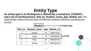
EntityType
An entity type in an ER diagram is defined by a name(here, STUDENT)
and a set of attributes(here, Roll_no, Student_name, Age, Mobile_no). The
table below shows how the data of different entities( different students) are
stored.
9.
UNIT -2 9
Typesof Entity type
1. What is a Strong Entity?
A strong entity is not dependent on any other entity in the schema
. A strong entity will always have a primary key. Strong entities are
represented by a single rectangle. The relationship of two strong
entities is represented by a single diamond. Various strong
entities, when combined together, create a strong entity set.
10.
UNIT -2 10
Whatis a Weak Entity?
A weak entity is dependent on a strong entity to ensure its
existence. Unlike a strong entity, a weak entity does not have any
primary key. It instead has a partial discriminator key. A
weak entity is represented by a double rectangle. The relation
between one strong and one weak entity is represented by a
double diamond. This relationship is also known as an identifying
relationship.
UNIT -2 13
EntitySet
Entity Set is a collection of entities of the same entity type. In
the above example of STUDENT entity type, a collection of
entities from the Student entity type would form an entity
set. We can say that entity type is a superset of the entity
set as all the entities are included in the entity type.
UNIT -2 15
Purposeand Benefits of ER Diagrams:
•Database Design:
They provide a clear and concise way to design the structure of a database
before implementation.
•Communication:
They facilitate communication between database designers, developers, and
stakeholders by visually representing the data model.
•Understanding Data Relationships:
They help in understanding how different data elements are related and how
information flows within a system.
•Reduced Complexity:
By providing a high-level view, they help manage the complexity of large and
intricate database systems.
16.
UNIT -2 16
Whatis a Relationship in a Database?
In a database, entities (like Students, Courses, Employees,
Projects, etc.) are real-world objects.
A relationship shows how two or more entities are connected.
Example of Relationships
•A Student enrolls in a Course.
“enrolls” is the relationship between Student and
→
Course.
•An Employee works on a Project.
“works_on” is the relationship between Employee and
→
Project.
17.
UNIT -2 17
Whatis a Relationship Attribute?
A relationship attribute is extra information that belongs to the
connection between two entities — not to the entities themselves.
Imagine This:
We have two entities:
1. Employee 2. Project
And a relationship:
Works_On meaning
→ an employee works on a project.
18.
UNIT -2 18
Now,ask:
Just saying “An employee works on a project” is not enough.
We may want to know more — like how many hours they work on
it.
That "extra" info — hours worked — does not belong to just
Employee or just Project.
It belongs to the relationship between them.
So, What is the Attribute?
Entity: Employee (name, ID, etc.)
Entity: Project (name, code, etc.)
Relationship: Works_On
Attribute: hours_per_week
NOTE: Important: It doesn’t belong to just one side.
19.
UNIT -2 19
RelationshipAttributes in 1:1 and 1:n Relationships
In some cases, the attributes of a relationship can be moved into
one of the related entities. This helps simplify the design.
What are 1:1 and 1:n?
1:1 (One-to-One)
One entity is related to only one other.
Example: One employee has one office.
1:n (One-to-Many)
One entity is related to many others.
Example: One department has many employees.
m:n (Many-to-Many) Relationships
20.
UNIT -2 20
Degreeof Relationship
This tells us how many entity types are involved in the
relationship.
Types:
Unary Relationship (Degree 1):
One entity related to itself.
Example: An employee manages another employee.
Binary Relationship (Degree 2):
Two entities involved.
Example: A student enrolls in a course.
Ternary Relationship (Degree 3):
Three entities involved.
Example: A doctor prescribes a medicine to a patient.
UNIT -2 23
5.Recursive relationship: A relationship between two entities of a similar entity
type is called a recursive relationship Here the same entity type participates
more than once in a relationship type with a different role for each instance
Student can be a class monitor and handle other students but a person who is
working as a class leader is itself a student of the class and hence a class
monitor has a recursive relationship of entity student
UNIT -2 37
Howto Draw ER Diagram?
1.The very first step is Identifying all the Entities, and place
them in a Rectangle, and labeling them accordingly.
2. The next step is to identify the relationship between
them and place them accordingly using the Diamond, and
make sure that, Relationships are not connected to each
other.
3. Attach attributes to the entities properly.
4. Remove redundant entities and relationships.
UNIT -2 40
ParticipationConstraints :
When each entity in an entity set participates in a relation, it is called Total Participation.
However, when all entities in the given entity set do not participate in a relation, it is
called Partial Participation.
UNIT -2 42
StructuralConstraints
The Structural constraints are represented by Min-Max notation. This is a pair of numbers(m,
n) that appear on the connecting line between the entities and their relationships.
UNIT -2 47
4.Key Constraints
StudentID Name Age
101 Alice 20
102 Bob 21
Primary Key (PK)
•Definition: A column or set of columns that uniquely identifies each row in a table.
•Characteristics:
•Unique for every row
•Cannot be NULL
•Example:
Here, StudentID is the Primary Key because it uniquely identifies each student.
48.
UNIT -2 48
4.Key Constraints
StudentID Name Age
101 Alice 20
102 Bob 21
2. Foreign Key (FK)
•Definition: A column (or set of columns) in one table that refers to the
Primary Key in another table.
•Purpose: To maintain relationships between tables.
•Example:
Student Table:
49.
UNIT -2 49
EnrollmentIDStudentID Course
1 101 Math
2 102 Science
Here, StudentID in Enrollment is a Foreign Key referring to StudentID in the Student table.
50.
UNIT -2 50
3.Alternate Key
•Definition: Any candidate key that is not chosen as the primary key.
•Example:
In a table:
StudentID (PK) Email (Alternate Key) Name
101 alice@example.com Alice
102 bob@example.com Bob
•StudentID is the primary key.
•Email is an alternate key (it can also uniquely identify a
•student but is not chosen as the primary key).
51.
UNIT -2 51
4.Candidate Key
•Definition: A set of one or more columns that can uniquely identify rows
in a table. Every candidate key could be chosen as a primary key.
•Example:
In the above student table:
•StudentID can uniquely identify each student.
•Email can also uniquely identify each student.
So, StudentID and Email are candidate keys.
52.
UNIT -2 52
•Candidatekeys are like all the options you have for picking a unique identifier in a table.
•When you choose one of those candidate keys to be the primary key, the rest of the
candidate keys become alternate keys.
So, alternate keys are a subset of candidate keys — just the ones you didn’t pick as the
primary key.
53.
UNIT -2 53
5.Super Key
•Definition: A set of columns that uniquely identifies rows in a table. It
may contain extra columns unnecessary for uniqueness.
•Example:
In the student table:
•StudentID alone is a super key.
•StudentID + Name together is also a super key (though Name is
unnecessary).
54.
UNIT -2 54
KeyType Meaning Example
Primary Key
Unique identifier for table
rows
StudentID
Foreign Key Refers to PK in another table StudentID in Enrollment
Candidate Key Potential PK (unique columns) StudentID, Email
Alternate Key
Candidate key not chosen as
PK
Email (if StudentID is PK)
Super Key
Any set that uniquely identifies
row
StudentID, StudentID+Name