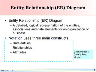
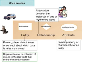
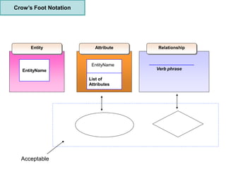
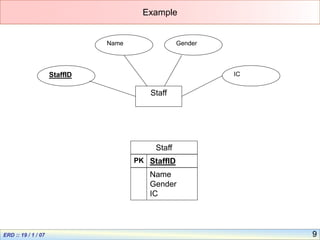
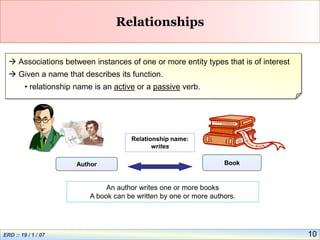
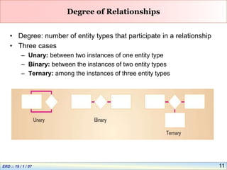
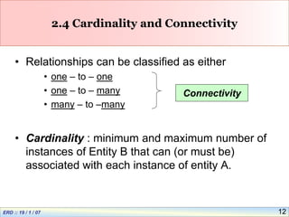
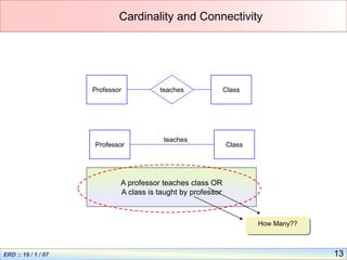
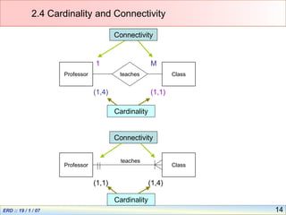
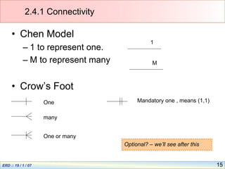
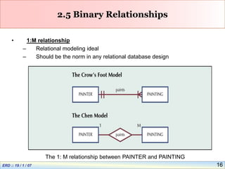
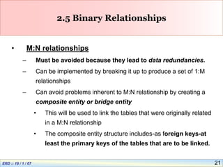
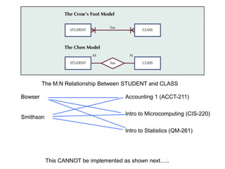
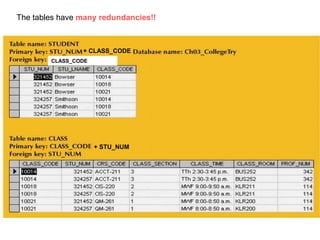
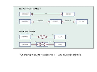
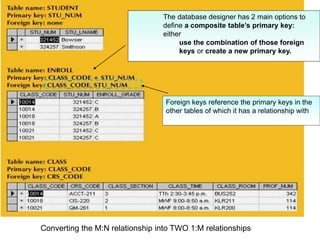
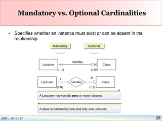
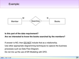
1
Entity Relationship Diagram
Objectives:
• (b) identify the entity set, attribute, relational set and
cardinality in data modelling;
• (c) use E-R diagrams to model data;
• (d) map the E-R diagram to a relational model: one-to-
one, one-to-many and many-to-many binary relationships;
2
Entity-Relationship (ER) Diagram
• Entity Relationship (ER) Diagram
– A detailed, logical representation of the entities,
associations and data elements for an organization or
business
• Notation uses three main constructs
– Data entities
– Relationships
– Attributes Chen Model &
Crow’s Foot
Model
Person, place, object, event
or concept about which data
is to be maintained
named property or
characteristic of an
entity
Association
between the
instances of one or
more entity types
Represents a set or collection of
objects in the real world that
share the same properties
Chen Notation
EntityName Verb Phrase AttributeName
Crow’s Foot Notation
EntityName
Entity Attribute
EntityName
List of
Attributes
Relationship
Verb phrase
Acceptable
5
Entities
• Examples of entities:
– Person: EMPLOYEE, STUDENT, PATIENT
– Place: STORE, WAREHOUSE
– Object: MACHINE, PRODUCT, CAR
– Event: SALE,REGISTRATION, RENEWAL
– Concept: ACCOUNT, COURSE
• Guidelines for naming and defining entity types:
– An entity type name is a singular noun
– An entity type should be descriptive and specific
– An entity name should be concise
– Event entity types should be named for the result of the event, not
the activity or process of the event.
6
Attributes
• Example of entity types and associated attributes:
STUDENT: Student_ID, Student_Name, Home_Address,
Phone_Number, Major
• Guidelines for naming attributes:
– An attribute name is a noun.
– An attribute name should be unique
– To make an attribute name unique and clear, each attribute name
should follow a standard format
– Similar attributes of different entity types should use similar but
distinguishing names.
7
2.2.1 Identifier Attributes
• Candidate key
– Attribute (or combination of attributes) that uniquely
identifies each instance of an entity type
– Some entities may have more than one candidate key
• Ex: A candidate key for EMPLOYEE is Employee_ID, a second is
the combination of Employee_Name and Address.
• If there is more than one candidate key, need to make a choice.
• Identifier
– A candidate key that has been selected as the unique
identifying characteristic for an entity type
8
2.2.2 Referential Attributes
Name IdNum DeptID Email
Ali 105 LG ali@a.com
Mary 106 IT mary@a.com
John 107 ENG john@a.com
Lim 108 IT lim@a.com
Instance of Lecturer.
Referential attribute: Ties the lecturer entity to
another entity that is department.
• Make Reference to another instance in another table
9
Example
Staff
StaffID
Name Gender
IC
Staff
StaffID
Name
Gender
IC
PK
10
Relationships
 Associations between instances of one or more entity types that is of interest
 Given a name that describes its function.
• relationship name is an active or a passive verb.
Author Book
Relationship name:
writes
An author writes one or more books
A book can be written by one or more authors.
11
Degree of Relationships
• Degree: number of entity types that participate in a relationship
• Three cases
– Unary: between two instances of one entity type
– Binary: between the instances of two entity types
– Ternary: among the instances of three entity types
12
2.4 Cardinality and Connectivity
• Relationships can be classified as either
• one – to – one
• one – to – many
• many – to –many
• Cardinality : minimum and maximum number of
instances of Entity B that can (or must be)
associated with each instance of entity A.
Connectivity
13
Cardinality and Connectivity
Professor Class
teaches
A professor teaches class OR
A class is taught by professor
How Many??
Professor Class
teaches
14
2.4 Cardinality and Connectivity
Professor Class
teaches
Professor Class
teaches
1 M
Connectivity
Connectivity
(1,1)
(1,1)
(1,4)
(1,4)
Cardinality
Cardinality
15
2.4.1 Connectivity
• Chen Model
– 1 to represent one.
– M to represent many
• Crow’s Foot
many
One
One or many
1
M
Mandatory one , means (1,1)
Optional? – we’ll see after this
16
2.5 Binary Relationships
• 1:M relationship
– Relational modeling ideal
– Should be the norm in any relational database design
The 1: M relationship between PAINTER and PAINTING
The Implemented 1:M relationship between PAINTER and PAINTING
18
2.5 Binary Relationships
• 1:1 relationship
– Should be rare in any relational database design
– A single entity instance in one entity class is related to a single entity
instance in another entity class
– Could indicate that two entities actually belong in the same table
The 1:1 Relationship Between PROFESSOR and DEPARTMENT
The Implemented
1:1 Relationship
Between
PROFESSOR
and
DEPARTMENT
21
2.5 Binary Relationships
• M:N relationships
– Must be avoided because they lead to data redundancies.
– Can be implemented by breaking it up to produce a set of 1:M
relationships
– Can avoid problems inherent to M:N relationship by creating a
composite entity or bridge entity
• This will be used to link the tables that were originally related
in a M:N relationship
• The composite entity structure includes-as foreign keys-at
least the primary keys of the tables that are to be linked.
The M:N Relationship Between STUDENT and CLASS
This CANNOT be implemented as shown next…..
Bowser
Smithson
Accounting 1 (ACCT-211)
Intro to Microcomputing (CIS-220)
Intro to Statistics (QM-261)
The tables have many redundancies!!
+ CLASS_CODE
CLASS_CODE
+ STU_NUM
Changing the M:N relationship to TWO 1:M relationships
Converting the M:N relationship into TWO 1:M relationships
Foreign keys reference the primary keys in the
other tables of which it has a relationship with
The database designer has 2 main options to
define a composite table’s primary key:
either
use the combination of those foreign
keys or create a new primary key.
26
Mandatory vs. Optional Cardinalities
• Specifies whether an instance must exist or can be absent in the
relationship
Lecturer Class
handles
A Lecturer may handle zero or many classes.
A class is handled by one and only one Lecturer.
Optional
Mandatory
(0,N)
(1,1)
Lecturer Class
(0,N) (1,1)
handles
1
M
27
How to Evaluate a Data Model?
• A good data model has the following:
– Accuracy and completeness
– Non redundancy
– Enforcement of business rules
– Data Reusability
– Stability and Flexibility
– Communication Effectiveness
– Simplicity
28
A Common Mistake
Modeling the business processes or functions
instead of the data.
What data we want to keep??
We are interested in modeling the data,
NOT the processes or functions that use
or generate those data.
29
Example:
Member Books
Searches
M N
Is this part of the data requirement?
Are we interested to know the books searched by the members?
If answer is NO, then DO NOT include that as a relationship.
Use other appropriate diagramming techniques to capture the business
processes such as Data Flow Diagram.
Do not mix up the use of ER Modeling with DFD.
30
~The END~
Q & A

entity-relationship-diagram-chen-&-crow -model.ppt

  • 1.
    1 Entity Relationship Diagram Objectives: •(b) identify the entity set, attribute, relational set and cardinality in data modelling; • (c) use E-R diagrams to model data; • (d) map the E-R diagram to a relational model: one-to- one, one-to-many and many-to-many binary relationships;
  • 2.
    2 Entity-Relationship (ER) Diagram •Entity Relationship (ER) Diagram – A detailed, logical representation of the entities, associations and data elements for an organization or business • Notation uses three main constructs – Data entities – Relationships – Attributes Chen Model & Crow’s Foot Model
  • 3.
    Person, place, object,event or concept about which data is to be maintained named property or characteristic of an entity Association between the instances of one or more entity types Represents a set or collection of objects in the real world that share the same properties Chen Notation EntityName Verb Phrase AttributeName
  • 4.
    Crow’s Foot Notation EntityName EntityAttribute EntityName List of Attributes Relationship Verb phrase Acceptable
  • 5.
    5 Entities • Examples ofentities: – Person: EMPLOYEE, STUDENT, PATIENT – Place: STORE, WAREHOUSE – Object: MACHINE, PRODUCT, CAR – Event: SALE,REGISTRATION, RENEWAL – Concept: ACCOUNT, COURSE • Guidelines for naming and defining entity types: – An entity type name is a singular noun – An entity type should be descriptive and specific – An entity name should be concise – Event entity types should be named for the result of the event, not the activity or process of the event.
  • 6.
    6 Attributes • Example ofentity types and associated attributes: STUDENT: Student_ID, Student_Name, Home_Address, Phone_Number, Major • Guidelines for naming attributes: – An attribute name is a noun. – An attribute name should be unique – To make an attribute name unique and clear, each attribute name should follow a standard format – Similar attributes of different entity types should use similar but distinguishing names.
  • 7.
    7 2.2.1 Identifier Attributes •Candidate key – Attribute (or combination of attributes) that uniquely identifies each instance of an entity type – Some entities may have more than one candidate key • Ex: A candidate key for EMPLOYEE is Employee_ID, a second is the combination of Employee_Name and Address. • If there is more than one candidate key, need to make a choice. • Identifier – A candidate key that has been selected as the unique identifying characteristic for an entity type
  • 8.
    8 2.2.2 Referential Attributes NameIdNum DeptID Email Ali 105 LG ali@a.com Mary 106 IT mary@a.com John 107 ENG john@a.com Lim 108 IT lim@a.com Instance of Lecturer. Referential attribute: Ties the lecturer entity to another entity that is department. • Make Reference to another instance in another table
  • 9.
  • 10.
    10 Relationships  Associations betweeninstances of one or more entity types that is of interest  Given a name that describes its function. • relationship name is an active or a passive verb. Author Book Relationship name: writes An author writes one or more books A book can be written by one or more authors.
  • 11.
    11 Degree of Relationships •Degree: number of entity types that participate in a relationship • Three cases – Unary: between two instances of one entity type – Binary: between the instances of two entity types – Ternary: among the instances of three entity types
  • 12.
    12 2.4 Cardinality andConnectivity • Relationships can be classified as either • one – to – one • one – to – many • many – to –many • Cardinality : minimum and maximum number of instances of Entity B that can (or must be) associated with each instance of entity A. Connectivity
  • 13.
    13 Cardinality and Connectivity ProfessorClass teaches A professor teaches class OR A class is taught by professor How Many?? Professor Class teaches
  • 14.
    14 2.4 Cardinality andConnectivity Professor Class teaches Professor Class teaches 1 M Connectivity Connectivity (1,1) (1,1) (1,4) (1,4) Cardinality Cardinality
  • 15.
    15 2.4.1 Connectivity • ChenModel – 1 to represent one. – M to represent many • Crow’s Foot many One One or many 1 M Mandatory one , means (1,1) Optional? – we’ll see after this
  • 16.
    16 2.5 Binary Relationships •1:M relationship – Relational modeling ideal – Should be the norm in any relational database design The 1: M relationship between PAINTER and PAINTING
  • 17.
    The Implemented 1:Mrelationship between PAINTER and PAINTING
  • 18.
    18 2.5 Binary Relationships •1:1 relationship – Should be rare in any relational database design – A single entity instance in one entity class is related to a single entity instance in another entity class – Could indicate that two entities actually belong in the same table
  • 19.
    The 1:1 RelationshipBetween PROFESSOR and DEPARTMENT
  • 20.
  • 21.
    21 2.5 Binary Relationships •M:N relationships – Must be avoided because they lead to data redundancies. – Can be implemented by breaking it up to produce a set of 1:M relationships – Can avoid problems inherent to M:N relationship by creating a composite entity or bridge entity • This will be used to link the tables that were originally related in a M:N relationship • The composite entity structure includes-as foreign keys-at least the primary keys of the tables that are to be linked.
  • 22.
    The M:N RelationshipBetween STUDENT and CLASS This CANNOT be implemented as shown next….. Bowser Smithson Accounting 1 (ACCT-211) Intro to Microcomputing (CIS-220) Intro to Statistics (QM-261)
  • 23.
    The tables havemany redundancies!! + CLASS_CODE CLASS_CODE + STU_NUM
  • 24.
    Changing the M:Nrelationship to TWO 1:M relationships
  • 25.
    Converting the M:Nrelationship into TWO 1:M relationships Foreign keys reference the primary keys in the other tables of which it has a relationship with The database designer has 2 main options to define a composite table’s primary key: either use the combination of those foreign keys or create a new primary key.
  • 26.
    26 Mandatory vs. OptionalCardinalities • Specifies whether an instance must exist or can be absent in the relationship Lecturer Class handles A Lecturer may handle zero or many classes. A class is handled by one and only one Lecturer. Optional Mandatory (0,N) (1,1) Lecturer Class (0,N) (1,1) handles 1 M
  • 27.
    27 How to Evaluatea Data Model? • A good data model has the following: – Accuracy and completeness – Non redundancy – Enforcement of business rules – Data Reusability – Stability and Flexibility – Communication Effectiveness – Simplicity
  • 28.
    28 A Common Mistake Modelingthe business processes or functions instead of the data. What data we want to keep?? We are interested in modeling the data, NOT the processes or functions that use or generate those data.
  • 29.
    29 Example: Member Books Searches M N Isthis part of the data requirement? Are we interested to know the books searched by the members? If answer is NO, then DO NOT include that as a relationship. Use other appropriate diagramming techniques to capture the business processes such as Data Flow Diagram. Do not mix up the use of ER Modeling with DFD.
  • 30.