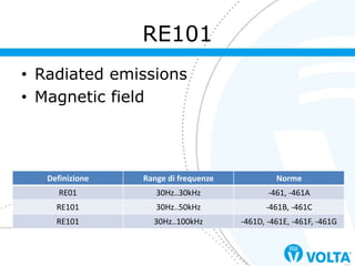
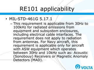
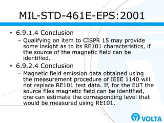
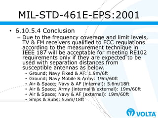
Analisi delle prove di misura di emissioni irradiate nell'ambito della norma MIL-STD-461G e paragone con le normative precedenti. Pubblicata in occasione del seminario MIL nel 2017.
Electromagnetic Interference and Electromagnetic Compatibility (EMI/EMCAishwary Singh
• Characterizing the threat
• Setting standards for emission and susceptibility levels
• Testing of Equipment on heavy Vibrations
• Testing for standards compliance
For queries,
Aishwarya
palsinghaishwarya@gmail.com
This document provides an overview of electromagnetic compatibility (EMC) testing, including conducted emission (CE), radiated emission (RE), conducted susceptibility (CS), and radiated susceptibility (RS) tests. It discusses the relevant standards for different types of equipment under test (EUT) and applications. Key aspects covered include test setup requirements, equipment used like EMI receivers, antennas, anechoic chambers, line impedance stabilization networks (LISNs), and turntables. The document also provides examples of EMC test equipment like antennas and absorber materials. Overall, it introduces the basic concepts and requirements for pre-compliance EMC testing.
Premier Filters offering an array of customize EMI Filters. MIL-STD-461 is one of them. In this slide, we have highlighted MIL-STD-461 testing, uses and more.
Analisi delle prove di suscettibilità condotta nell'ambito della norma MIL-STD-461G e paragone con le normative precedenti. Pubblicata in occasione del seminario MIL nel 2017.
This document provides an overview of electromagnetic interference (EMI) and electromagnetic compatibility (EMC). It defines EMI as an electromagnetic disturbance that can degrade equipment performance or cause malfunctions. EMC is described as a state where equipment functions satisfactorily in a common electromagnetic environment without intolerably disturbing other equipment. The document outlines common sources and effects of EMI and techniques to control EMI at its source, including proper grounding, shielding, filtering, and printed circuit board layout. It also discusses important EMI/EMC standards and standards bodies.
EMI refers to electromagnetic interference, or unwanted electromagnetic signals that can disrupt other electronic devices. EMC refers to electromagnetic compatibility, which is the ability of a device to function properly without disrupting or being disrupted by other electromagnetic signals. Electronic products must meet EMI and EMC standards before being released to ensure they do not interfere with other devices and are not interfered with themselves. Following design guidelines and using EMI-compliant components can help products pass EMI/EMC tests on the first try.
The document provides an overview of electromagnetic interference (EMI) and electromagnetic compatibility (EMC). It defines EMI and EMC, discusses sources of EMI including natural and man-made sources. Case studies of accidents caused by EMI are presented. Techniques for controlling EMI such as grounding, shielding and filtering are described. Military and civilian EMC standards are also discussed. The document concludes that EMC means that equipment operates correctly in the presence of EMI without itself causing intolerable interference.
Electro magnetic interference and compatibility(ECM,ECI)Palani murugan
Electromagnetic interference (EMI) can negatively impact electrical/electronic equipment by creating undesirable responses or failure. Electromagnetic compatibility (EMC) aims to allow equipment to function properly in the intended environment without degradation from EMI. EMI can be radiated through electromagnetic fields or conducted through physical contact. Common techniques to control EMI include grounding, shielding, and filtering. Proper layout design can also help prevent EMI and ensure EMC.
The document discusses electromagnetic compatibility (EMC) immunity testing standards. It focuses on electrostatic discharge (ESD), electrical fast transients (EFT), surge, radiated immunity, and conducted immunity tests. For each test, it describes the purpose, needed equipment, test setup, procedures, performance criteria, standards, and other test considerations. The performance criteria classify immunity test results into four categories based on the equipment's performance.
This document discusses radiated susceptibility testing standards and procedures. It provides an overview of various radiated susceptibility test methods (RS101, RS103, RS105) defined in MIL-STD-461G, including applicable frequency ranges and equipment. It also compares these test methods to relevant IEC commercial standards. The document outlines the specific test setup, equipment, and procedures required to perform radiated susceptibility integrity checks and testing according to MIL-STD-461G for equipment under test.
This document discusses EMI/EMC, including various sources of electromagnetic interference and transients that can affect electronic systems, such as crosstalk between transmission lines, switching transients, and lightning strikes. It also covers open area test sites and measurements for evaluating radiated emissions and susceptibility of equipment to electromagnetic fields. Key points include the importance of minimizing scattering at test sites, and using antennas and measurement precautions appropriately based on frequency ranges and standards.
This document provides an overview of electromagnetic interference (EMI) test methods and instrumentation. It defines electromagnetic compatibility (EMC) and describes the electromagnetic environment. Common EMI sources and victims are identified. Key EMI test methods are outlined, including radiated emission (RE) testing, conducted emission (CE) testing, radiated susceptibility (RS) testing, and conducted susceptibility (CS) testing. Critical EMI testing facilities and instrumentation are discussed, such as anechoic chambers, shield rooms, open area test sites (OATS), EMI test receivers, spectrum analyzers, and EMI test signal generators. EMC regulations and standards around the world are also briefly summarized.
Introduction
Aspects of EMC
Definitions
Electrical Dimensions and Waves
EMC Requirements for Electronic Systems
Effects of EME/EM Interference
EMC Testing Routine
List of EME and EMI Tests
Avoid EMC Failure
EMC EMI testing standard :CISPR 16
EMI EMC standard for testing: IEC 61000
Typical EMC Test Facilities
Semi-Anechoic Chamber (10m) configuration
Limits and Test for Radiated Emission(RE) and Conducted Emission(CE)
Test for Radiated Susceptibility(RS), Conducted Susceptibility(CS) and Electrostatic Discharge(ESD)
This document discusses the ongoing challenges of automotive electromagnetic compatibility (EMC) compliance as vehicles integrate more electronic technologies. It notes the increasing number of electronic components creates greater EMC demands, while simplified signaling protocols aim to help control the situation. Engineers are modifying tools to simulate electromagnetic fields at higher frequencies and voltages. Vehicle manufacturers must ensure new modules meet EMC standards and that standards reflect future installations, which is challenging as vehicles add hybrid and electric propulsion systems and independent manufacturers enter the market.
Introduction To Electromagnetic CompatibilityJim Jenkins
Here are a few key points about ground in the context of electromagnetic compatibility (EMC):
- Ground is a common reference point in an electrical system that all other voltages are measured against. It establishes a baseline voltage level.
- In EMC, ground plays an important role in providing a return path for electromagnetic interference (EMI) currents. These currents, known as common mode currents, flow on cables and are looking for a way to complete their circuit back to the source.
- An ideal ground would have zero impedance and instantly drain away any EMI currents. In reality, all grounds have some finite impedance that can allow currents to couple into other circuits.
- Different grounding schemes are used, such
This document provides an introduction to electromagnetic compatibility (EMC). It discusses key topics related to EMC including the EMI environment, EMC design approaches, immunity and susceptibility, EMI modeling and prediction, compliance testing, and EMC costs. The goal of the module is to explain the fundamentals of EMC and how it can be addressed through various design, testing and compliance strategies.
Any training class is a considerable investment in terms of cost and your time. You can’t afford to waste any of your precious time and you need to attend something that is useful and improves your productivity. After five years of presentation throughout the world, this workshop is well polished, practical and relevant.
The aim of this workshop is to help you identify, design, prevent and fix common EMI/EMC problems with a focus on earthing and shielding techniques. Learning how to fix earthing and shielding problems on the job can be very expensive and frustrating. Although it must be noted that most of the principles involved are simple, this workshop will give you the tools to approach earthing and shielding issues in a logical and systematic way.
This workshop focuses on the issues of interest to you if you are working in design, operation or maintenance of analog or digital systems involving sensors, data acquisition, process control, cables, signal processing, programmable logic controllers, power distribution, high speed logic etc.
The circuit board layout section concentrates on design and layout of circuits and components on a printed circuit board. The overall focus is on useful design and systems issues; not about regulations and standards. The idea is that you will take this material back with you to your work and apply the key principles immediately to your design and troubleshooting challenges.
WHO SHOULD ATTEND?
Building service designers
CAD managers
Consulting engineers
Data systems planners and managers
Design engineers
Electrical and instrumentation technicians
Electrical contractors
Electrical engineers
Electrical inspectors
Electricians
EMC specialists
Electronics and systems engineers and technicians
Instrumentation and control engineers
Logic designers
Maintenance engineers
Mechanical engineers
Power system protection and control engineers
Printed circuit board designers
Project engineers
Safety professionals
Signal integrity specialists
Technical managers
Test engineers
MORE INFORMATION: http://www.idc-online.com/content/practical-shielding-emcemi-noise-reduction-earthing-and-circuit-board-layout-66
This document outlines an RF fundamentals course taught in 3 modules. Module 1 covers basics of RF including frequency, amplitude, wavelength, phase, and polarization. It also discusses transmission line fundamentals. Module 2 discusses RF communication systems, modulation techniques, and RF design. Module 3 covers wireless technologies like Bluetooth, WiFi, and cellular standards. The course provides assignments on topics like wavelength calculation and transmission line speed calculation in different materials. It also explains dBm calculations and concepts like signal to noise ratio, gain and loss.
An optical fiber coupler is a device that splits light from one fiber into multiple fibers. There are different types of couplers classified by their shape, including Y, T, X, star, and tree couplers. Couplers work by transferring power between fibers through their cores or surfaces. Examples show how to calculate excess loss, insertion loss, crosstalk, and splitting ratios using the measured input and output powers. Optical couplers have applications in splitting and combining optical signals in fiber networks and communication systems.
This document provides information about electromagnetic interference (EMI) measurements and standards. It discusses EMI test facilities like shielded chambers, open area test sites, and EMI receivers and spectrum analyzers used for testing. It also covers various EMI standards from organizations like CISPR, FCC, IEC, EN, and MIL for both civilian and military applications. Measurement methods for radiated and conducted emissions are described.
Presentation on emc testing and measurementRajat Soni
discuss the options for EMC testing for compliance with the EMC Directive from the point of view of a manufacturer who wishes to achieve as much progress as possible, in-house, on a limited budget. It is not addressed to test houses nor to those manufacturers who have the resources to emulate most or all of the facilities of an accredited test house in their own premises. There are many small-to-medium sized enterprises who are able to dedicate a modest budget of several thousands or tens of thousands of pounds to an in-house EMC test set-up and who wish to gain the maximum benefit from so doing.
This document provides an overview of electromagnetic interference (EMI) and electromagnetic compatibility (EMC). It discusses sources of EMI such as atmospheric noise from lightning and clouds. It also describes four coupling mechanisms by which EMI can occur: conductive, capacitive, inductive, and radiative. Techniques for controlling EMI are then outlined, including grounding, shielding, and filtering. Finally, the document discusses methods for EMC testing, including evaluating emissions and susceptibility through radiated field, conducted, and transient immunity testing.
Basic blocks to understand RFFE Architecture. how Analog front end and Digital front is different. Basic components like Filter, Mixer, Power Amplifier, circulator, Duplexer, LNA and demodulator working is explained. It can held to design your own front end as RF link budget has been explained in well manner. what to do to avoid saturation of PA?
Optimized Local I/O ESD Protection for SerDes In Advanced SOI, BiCMOS and Fin...Sofics
Sofics presentation (B2.2) at the 1st International EOS/ESD Symposium on Design and System (IEDS). IEDS is dedicated to the fundamental understanding of issues related to electrostatic discharge on design and system and the application of this knowledge to the solution of problems.
Semiconductor companies are developing ever faster interfaces to satisfy the need for higher data throughputs. However, the parasitic capacitance of the traditional ESD solutions limits the signal frequency. This paper demonstrates low-cap Analog I/Os for high speed SerDes (28Gbps to 112Gbps) circuits created in advanced BiCMOS, SOI and FinFET nodes.
This document provides information about electromagnetic interference (EMI) and electromagnetic compatibility (EMC) testing. It describes typical EMC test facilities like semi-anechoic chambers and shield rooms. It also outlines various EMC tests including radiated emission testing, conducted emission testing, radiated susceptibility testing, conducted susceptibility testing, and electrostatic discharge testing. Standards and procedures for performing these tests are discussed. The goal of EMC testing is to ensure electronic systems do not interfere with other systems and continue operating correctly despite electromagnetic interference.
Analisi delle prove di misura di emissioni condotte nell'ambito della norma MIL-STD-461G e paragone con le normative precedenti. Pubblicata in occasione del seminario MIL nel 2017.
The document discusses simulation and testing of antennas for 4G LTE-MIMO systems. It describes simulating a PIFA antenna in CST Studio Suite to compare matched and unmatched cases. Results showed improved return loss and far-field patterns when the antenna was matched. Testing of a MIMO antenna system involved measuring isolation between antennas and comparing performance with the enclosure open versus closed.
This document describes the design of an ultra wide band antenna for tactical communication systems. It proposes designing a rectangular patch antenna with a corner slot and coplanar microstrip feeding to operate in the 3.1-10.6 GHz band. The design methodology involves using HFSS simulation software to optimize the patch dimensions, substrate thickness and material to achieve good return loss, impedance matching and omnidirectional radiation patterns over the band. Simulation results are presented and show the antenna meets requirements for tactical communication applications.
The document summarizes the C/A code and its properties in GPS. It describes that the C/A code is used to (1) enable accurate range measurements, (2) permit simultaneous measurements from multiple satellites, and (3) provide protection from jamming. It then discusses the P-code and Y-code, the L1 and L2 carriers, signal power levels, acquisition and tracking in GPS receivers, and extracting information from signals for navigation solutions.
A Multiband Printed Antenna Suitable for Wireless ApplicationsTELKOMNIKA JOURNAL
This study deals with a new research work on a low cost multiband printed antenna
which can be used for three operating frequency bands GSM900/PCS/WIFI/Bluetooth. The
achieved antenna is mounted on an FR-4 substrate. In this study, the solts technique is used to
obtain the multiband behavior. The different solts are inserted in the radiator face and the back
face that is the ground. The whole circuit is optimized taking into account the good matching of
the input impedance in the operating frequency bands with a stable radiation pattern. In order to
optimize the proposed antenna structure we have used CST-MW and to compare the obtained
simulation results we have conducted another electromagnetic simulation by using HFSS
solver. The final circuit validated into simulation has been fabricated and tested which permits to
validate the proposed multiband antenna.
TV Repack & ATSC 3.0: SFN & Future proofing antennaskmsavage
This document summarizes a presentation about planning for TV repack and futureproofing antennas for ATSC 3.0. It discusses the incentive auction timeline, how many stations will be directly impacted, the process for stations moving to new channels after the auction. It covers considerations for antennas on lower channels like needing larger/heavier antennas. It also discusses futureproofing antennas for ATSC 3.0 like adding more null fill or making antennas compatible with single frequency networks. Signal strength requirements for different types of services are presented. Network planning assumptions and an example for a station in Baltimore are provided.
This document discusses various topics related to microwave and satellite communication systems including:
1. Microwave systems are classified as long haul or short haul based on the distance served and frequency bands used. Common frequency bands include 2GHz, 4GHz, 6GHz, 7GHz, and 11GHz.
2. Satellites can provide communication services from various orbits including Low Earth Orbit (LEO), Medium Earth Orbit (MEO), and Geosynchronous Earth Orbit (GEO). A transponder on each satellite receives and retransmits signals to allow communication between Earth stations.
3. Factors like orbit altitude, orbital speed, and rotation period distinguish different categories of satellites like LEO, MEO,
The document summarizes a research paper on the design of a frequency reconfigurable monopole antenna with a switchable symmetric slot structure. The antenna is designed to operate across multiple frequency bands by using p-i-n diodes to switch the state of the symmetric slot structure on the ground plane. Five diode combinations are identified that allow the antenna to operate at different single and dual frequency bands between 1.72-9.57 GHz. The simple and compact antenna design makes it suitable for applications requiring reconfiguration across multiple frequency bands like cognitive radio and multi-radio wireless systems.
This document discusses the interference problems that can occur between 850 MHz and 900 MHz networks when deployed in the same area. It focuses specifically on out-of-band emissions from 850 MHz base transceiver stations entering the 900 MHz uplink band. Through a link budget analysis using typical deployment assumptions, it determines the required attenuation of filters needed at various site-to-site distances and antenna isolation levels to reduce interference below sensitivity degradation thresholds. The analysis finds that filtering is necessary, as interference levels without it exceed permissible levels and could degrade coverage up to 6%. The exact attenuation required depends on several network parameters.
Access the video from this presentation for free from
http://www.rohde-schwarz-usa.com/DebuggingEMISS_On-Demand.html
Overview:
Electromagnetic interference is increasingly becoming a problem in complex systems that must interoperate in both digital and RF domains. When failures due to EMI occur it is often difficult to track down the sources of such failures using standard test receivers and spectrum analyzers. The unique ability of real-time spectrum analysis and synchronous time domain signal acquisition to capture transient events can quickly reveals details about the sources of EMI.
What You Will Learn:
How to isolate and analyze sources of EMI using an oscilloscope
Measurement considerations for correlating time and frequency domains
Near field probing basics
Presented By:
Dave Rishavy, Product Manager Oscilloscopes, Rohde & Schwarz
Dave Rishavy has a BS in Electrical Engineering from Florida State University and an MBA from the University of Colorado. Prior to joining Rohde and Schwarz, Mr. Rishavy gained over 15 years of experience in the test and measurement field at Agilent Technologies. This included positions in a wide range of technical marketing areas such as application engineering, product marketing, marketing management and strategic product planning. While at Agilent, Dave led the marketing and industry segment teams for the Infiniium line of oscilloscopes as well as high end logic analysis.
An Earth Station Technology PPT 7- Lecture 7.pptxAhmedWasiu
This document provides an overview of satellite communication earth station design and testing. It discusses key considerations for earth station design including requirements specifications, cost-effective architecture, and key performance parameters. It also covers earth station standards, design optimization for reliability, environmental and site considerations, hardware components including RF, IF and baseband equipment, and terrestrial interfaces. Testing procedures for earth stations including mandatory tests, additional tests, and line-up tests are also outlined.
The document discusses operating status displays for a DC drive. It provides detailed explanations of status codes that may appear, ranging from "o1 Waiting for operating enable" to "o11 Fault". The statuses indicate conditions like waiting for voltage, field current, switch-on command, or acknowledgement of faults. Fault codes are also explained. Proper EMC installation guidelines are provided, such as routing signal and power cables separately and connecting cable shields to ground.
Technical specification for 3.ph 4 wire stw 12 02-11laxman prasad
The document provides a technical specification for a 3-phase, 4-wire solid state whole current lag only energy meter with an LCD display. Key details include:
- It is to be used for balanced/unbalanced loads in shallow tube well pump sets with an accuracy class of 1.0 and a current rating of 10-60 amps.
- The meter must comply with various Indian and international standards for electricity meters.
- It must be able to operate under tropical climatic conditions with high temperatures, humidity, and rainfall.
- Electrical specifications include a class 1.0 accuracy, 240V supply voltage, 50Hz frequency, and power factor range of zero lag to unity to zero lead.
IRJET- Design of Dual Frequency Probe Fed Microstrip Antenna using Shorting WallIRJET Journal
This document describes the design of a dual frequency microstrip antenna using a shorting wall. It presents the cavity model used to simulate the antenna and analyzes the effects of the shorting wall on input impedance. The antenna was designed using ANSOFT HFSS software and fabricated using a substrate with a copper-clad on both sides. Results showed that increasing the height of the shorting wall causes the antenna to resonate at higher frequencies, while decreasing the height causes resonance at lower frequencies, allowing multi-band operation. Both simulated and experimental results agreed and demonstrated dual-band operation of the antenna.
Analisi della filosofia si cui si è basato lo sviluppo della norma MIL-STD-461 dalla sua nascita fino alla versione attuale -461G. Pubblicata in occasione del seminario MIL nel 2017.
Millimeter wave circular microstrip Patch antenna for 5 g applicationsGana U Kumar
The document describes the design of a millimeter wave microstrip patch antenna for 5G applications operating at 28GHz. Key points:
1) A circular microstrip patch antenna was designed on Roger RT/duroid 5880 substrate with dielectric constant of 2.2 and thickness of 0.508mm.
2) The antenna was simulated using HFSS and achieved over 7dB gain, bandwidth over 1GHz, and return loss below -15dB at the target frequency of 28GHz.
3) To further increase gain, a 1x4 circular patch antenna array was designed and is expected to improve performance over a single element for 5G communication systems.
This document discusses E band (60-90GHz) and V band (40-75GHz) spectrum allocations and characteristics. Some key points:
- E band has a transmission distance of up to 3km while V band is shorter at around 300m, making them suitable for dense urban deployments.
- Both bands allow for heavy frequency reuse due to their pencil beam propagation and inability to penetrate walls. This means they can support many links without interference.
- Large channel bandwidths are available, up to 10GHz in E band and 7GHz in V band, allowing for high throughput backhaul and connectivity solutions.
- There is debate around licensing these bands, with some arguing they should be
This document discusses using spectrum analyzers for signal monitoring systems. Spectrum analyzers can form the foundation of many signal monitoring systems as they can measure frequency and amplitude of signals. Basic components of a signal monitoring system include a spectrum analyzer receiver, antenna, transmission lines, and optionally a preamplifier. The document focuses on using Agilent's PSA series spectrum analyzers, which are well-suited for signal monitoring due to their broad frequency coverage and measurement functions. Key factors for the antenna include gain, bandwidth, polarization, and impedance match. Signal monitoring can be used for frequency management, signal surveillance, and law enforcement applications.
The document discusses guidelines for monitoring and controlling signal leakage from cable television systems. Key points include:
1. Cable operators must regularly patrol their systems to detect and log any signal leaks and make repairs.
2. Leakage is measured in microvolts per meter (uV/m) and systems have limits for the Cumulative Leakage Index (CLI) and Equivalent Leakage Density (ELD) to prevent interference.
3. Procedures for measuring, categorizing, and calculating CLI and ELD are provided according to Canadian regulatory guidelines. Systems must maintain CLI below 64 and meet decreasing ELD limits over time.
Presentazione di base relativa ai concetti della Compatibilità Elettromagnetica (EMC). Nello scritto si trovano informazioni sulle normative iEC, sugli ambienti e sulla loro struttura, sulle prove irradiate e sulle prove condotte.
Analisi delle strutture per prove di suscettività irradiata nell'ambito della sezione RS105 della norma MIL-STD-461G. Pubblicata in occasione del seminario MIL nel 2017.
DI-EMCS - Contro procedures, test procedures e test reportAlessandro Corniani
Analisi delle normative militari concernenti la compatibilità elettromagnetica e, in particolare, i Data Item EMC relativi alle procedure di prova, alle procedure di controllo ed alla stesura dei report. Pubblicata in occasione del seminario MIL nel 2017.
An improved modulation technique suitable for a three level flying capacitor ...IJECEIAES
This research paper introduces an innovative modulation technique for controlling a 3-level flying capacitor multilevel inverter (FCMLI), aiming to streamline the modulation process in contrast to conventional methods. The proposed
simplified modulation technique paves the way for more straightforward and
efficient control of multilevel inverters, enabling their widespread adoption and
integration into modern power electronic systems. Through the amalgamation of
sinusoidal pulse width modulation (SPWM) with a high-frequency square wave
pulse, this controlling technique attains energy equilibrium across the coupling
capacitor. The modulation scheme incorporates a simplified switching pattern
and a decreased count of voltage references, thereby simplifying the control
algorithm.
Design and optimization of ion propulsion dronebjmsejournal
Electric propulsion technology is widely used in many kinds of vehicles in recent years, and aircrafts are no exception. Technically, UAVs are electrically propelled but tend to produce a significant amount of noise and vibrations. Ion propulsion technology for drones is a potential solution to this problem. Ion propulsion technology is proven to be feasible in the earth’s atmosphere. The study presented in this article shows the design of EHD thrusters and power supply for ion propulsion drones along with performance optimization of high-voltage power supply for endurance in earth’s atmosphere.
Software Engineering and Project Management - Introduction, Modeling Concepts...Prakhyath Rai
Introduction, Modeling Concepts and Class Modeling: What is Object orientation? What is OO development? OO Themes; Evidence for usefulness of OO development; OO modeling history. Modeling
as Design technique: Modeling, abstraction, The Three models. Class Modeling: Object and Class Concept, Link and associations concepts, Generalization and Inheritance, A sample class model, Navigation of class models, and UML diagrams
Building the Analysis Models: Requirement Analysis, Analysis Model Approaches, Data modeling Concepts, Object Oriented Analysis, Scenario-Based Modeling, Flow-Oriented Modeling, class Based Modeling, Creating a Behavioral Model.
Use PyCharm for remote debugging of WSL on a Windo cf5c162d672e4e58b4dde5d797...shadow0702a
This document serves as a comprehensive step-by-step guide on how to effectively use PyCharm for remote debugging of the Windows Subsystem for Linux (WSL) on a local Windows machine. It meticulously outlines several critical steps in the process, starting with the crucial task of enabling permissions, followed by the installation and configuration of WSL.
The guide then proceeds to explain how to set up the SSH service within the WSL environment, an integral part of the process. Alongside this, it also provides detailed instructions on how to modify the inbound rules of the Windows firewall to facilitate the process, ensuring that there are no connectivity issues that could potentially hinder the debugging process.
The document further emphasizes on the importance of checking the connection between the Windows and WSL environments, providing instructions on how to ensure that the connection is optimal and ready for remote debugging.
It also offers an in-depth guide on how to configure the WSL interpreter and files within the PyCharm environment. This is essential for ensuring that the debugging process is set up correctly and that the program can be run effectively within the WSL terminal.
Additionally, the document provides guidance on how to set up breakpoints for debugging, a fundamental aspect of the debugging process which allows the developer to stop the execution of their code at certain points and inspect their program at those stages.
Finally, the document concludes by providing a link to a reference blog. This blog offers additional information and guidance on configuring the remote Python interpreter in PyCharm, providing the reader with a well-rounded understanding of the process.
Redefining brain tumor segmentation: a cutting-edge convolutional neural netw...IJECEIAES
Medical image analysis has witnessed significant advancements with deep learning techniques. In the domain of brain tumor segmentation, the ability to
precisely delineate tumor boundaries from magnetic resonance imaging (MRI)
scans holds profound implications for diagnosis. This study presents an ensemble convolutional neural network (CNN) with transfer learning, integrating
the state-of-the-art Deeplabv3+ architecture with the ResNet18 backbone. The
model is rigorously trained and evaluated, exhibiting remarkable performance
metrics, including an impressive global accuracy of 99.286%, a high-class accuracy of 82.191%, a mean intersection over union (IoU) of 79.900%, a weighted
IoU of 98.620%, and a Boundary F1 (BF) score of 83.303%. Notably, a detailed comparative analysis with existing methods showcases the superiority of
our proposed model. These findings underscore the model’s competence in precise brain tumor localization, underscoring its potential to revolutionize medical
image analysis and enhance healthcare outcomes. This research paves the way
for future exploration and optimization of advanced CNN models in medical
imaging, emphasizing addressing false positives and resource efficiency.
Rainfall intensity duration frequency curve statistical analysis and modeling...bijceesjournal
Using data from 41 years in Patna’ India’ the study’s goal is to analyze the trends of how often it rains on a weekly, seasonal, and annual basis (1981−2020). First, utilizing the intensity-duration-frequency (IDF) curve and the relationship by statistically analyzing rainfall’ the historical rainfall data set for Patna’ India’ during a 41 year period (1981−2020), was evaluated for its quality. Changes in the hydrologic cycle as a result of increased greenhouse gas emissions are expected to induce variations in the intensity, length, and frequency of precipitation events. One strategy to lessen vulnerability is to quantify probable changes and adapt to them. Techniques such as log-normal, normal, and Gumbel are used (EV-I). Distributions were created with durations of 1, 2, 3, 6, and 24 h and return times of 2, 5, 10, 25, and 100 years. There were also mathematical correlations discovered between rainfall and recurrence interval.
Findings: Based on findings, the Gumbel approach produced the highest intensity values, whereas the other approaches produced values that were close to each other. The data indicates that 461.9 mm of rain fell during the monsoon season’s 301st week. However, it was found that the 29th week had the greatest average rainfall, 92.6 mm. With 952.6 mm on average, the monsoon season saw the highest rainfall. Calculations revealed that the yearly rainfall averaged 1171.1 mm. Using Weibull’s method, the study was subsequently expanded to examine rainfall distribution at different recurrence intervals of 2, 5, 10, and 25 years. Rainfall and recurrence interval mathematical correlations were also developed. Further regression analysis revealed that short wave irrigation, wind direction, wind speed, pressure, relative humidity, and temperature all had a substantial influence on rainfall.
Originality and value: The results of the rainfall IDF curves can provide useful information to policymakers in making appropriate decisions in managing and minimizing floods in the study area.
2. • Radiated emissions
• Magnetic field
RE101
Definizione Range di frequenze Norme
RE01 30Hz..30kHz -461, -461A
RE101 30Hz..50kHz -461B, -461C
RE101 30Hz..100kHz -461D, -461E, -461F, -461G
3. Applicazioni MIL-STD-461G RE101
Surface ships A
Submarines A
Aircraft, Army, Including Flight Line A
Aircraft, Navy L
Aircraft, Air Force
Space systems, Including Launch Vehicles
Ground, Army
Ground, Navy
Ground, Air Force
Le applicazioni
A: Applicable
L: Limited as specified in the individual sections of the standard
S: Procuring activity must specify in procurement documentation
4. • MIL-STD-461G 5.17.1
– This requirement is applicable from 30Hz to
100kHz for radiated emissions from
equipment and subsystem enclosures,
including electrical cable interfaces. The
requirement does not apply to radiation
from antennas. For Navy aircraft, this
requirement is applicable only for aircraft
with ASW equipment which operates
between 30Hz and 10kHz such as: Acoustic
(Sonobouy) Receivers or Magnetic Anomaly
Detectors (MAD).
RE101 applicability
5. • RE101 vs.
– CISPR 15: Limits and methods of
measurement of radio disturbance
characteristics of electrical lighting and
similar equipment
– IEEE 1140: IEEE Standard Procedures
for the Measurement of Electric and
Magnetic Fields from Video Display
Terminals (VDTs) from 5Hz to 400kHz
MIL-STD-461E-EPS
7. Test parameter RE101 CISPR 15 IEEE 1140
Frequency range 30Hz..100kHz 9kHz..30MHz 5Hz..400Hz
Equipment type Unrestricted
Non-incandescent
lighting devices,
fn≥100Hz, l3.6m
Video display terminals
Test set-up
Table-top, floor-mounted,
bonded as in typical use
EUT grounded as in
typical use
As in typical use, ground
plane not required
Test method
Surface or cable scan at
7cm
3-axis loop large loop
antenna (Ø1..4m) with
current probes to
measure current in loops
Small loop at 0.5m
distance
Limits
Different in submarine
and army
RE101 is much more
severe
No limits: refer to
regulatory requirements
MIL-STD-461E-EPS:2001
8. • 6.9.1.4 Conclusion
– Qualifying an item to CISPR 15 may provide
some insight as to its RE101 characteristics, if
the source of the magnetic field can be
identified.
• 6.9.2.4 Conclusion
– Magnetic field emission data obtained using
the measurement procedure of IEEE 1140 will
not replace RE101 test data. If, for the EUT the
source files magnetic field can be identified,
one can estimate the corresponding level that
would be measured using RE101.
MIL-STD-461E-EPS:2001
9. • 5.17.3.2: Test equipment
– Measurement receivers
– Data recording device
– Loop sensor
• Diameter: Ø13.3cm
• Turns: 36
• Wire: DC resistance 5..10Ohm
• Shielding: electrostatic
• Correction factor
– LISNs
– Ohmmeter
– Signal generator
MIL-STD-461G
10. • 5.17.3.4.b
– Applicare un segnale a 50Hz, almeno
6dB inferiore al limite e verificare che il
livello ricevuto dal ricevitore sia
nell’intorno di ±3dB
– Con l’ohmmetro, verificare che la
resistenza del loop sia circa 10Ohm
Integrity check
12. • 5.17.3.4.c
– Azionare l’EUT e lasciarlo stabilizzare
– Porre il loop a 7cm dal lato del provino o
dal connettore in prova e orientarlo
parallelo
– Scansire sul range di frequenza con la
bandwidth e il tempo minimo di misura
da Table II e definire le frequenze di
massimo irraggiamento
EUT testing
13. • 5.17.3.4.c
– Soffermandosi sulle frequenze definite
prima, muovere il loop nei dintorni del
provino, mantenendosi sempre a 7cm
– Al punto di massimo irraggiamento,
inclinare l’asse del loop per trovare il
valore massimo limite
– Ripetere per almeno due frequenze
sotto 200Hz e tre sopra 200Hz
– Ripetere per ogni lato dell’EUT
EUT testing
15. • Radiated emissions
• Electric field
RE102
Definizione Range di frequenze Norme
RE02 14kHz..10GHz -461, -461A, -461B, -461C
RE102 10kHz..18GHz -461D, -461E, -461F, -461G
16. Applicazioni MIL-STD-461G RE102
Surface ships A
Submarines A
Aircraft, Army, Including Flight Line A
Aircraft, Navy A
Aircraft, Air Force A
Space systems, Including Launch Vehicles A
Ground, Army A
Ground, Navy A
Ground, Air Force A
Le applicazioni
A: Applicable
L: Limited as specified in the individual sections of the standard
S: Procuring activity must specify in procurement documentation
17. • MIL-STD-461G 5.18.1
– This requirement is applicable for radiated
emissions from equipment and subsystem
enclosures, and all interconnecting cables. For
equipment with permanently mounted antennas
this requirement does not apply at the transmitter
fundamental frequency and the necessary occupied
bandwidth of the signal. The requirement is
applicable as follows:
• a. Ground: 2MHz to 18GHz
• b. Ships, surface: 10kHz to 18GHz
• c. Submarines: 10kHz to 18GHz
• d. Aircraft (Army and Navy): 10kHz to 18GHz
• e. Aircraft (Air Force): 2MHz to 18GHz
• f. Space: 10kHz to 18GHz
RE102 applicability
18. • MIL-STD-461F 5.17.1
– *Testing is required up to 1 GHz or 10
times the highest intentionally
generated frequency within the EUT,
whichever is greater. Measurements
beyond 18 GHz are not required.
• La limitazione viene tolta nella -461G
e i requirements richiedono tutti di
arrivare a 18GHz
RE102 applicability
19. • RE102 vs.
– CISPR 11: Industrial, scientific and
medical equipment - Radio-frequency
disturbance characteristics - Limits and
methods of measurement
– CISPR 22: Information technology
equipment - Radio disturbance
characteristics - Limits and methods of
measurement
MIL-STD-461E-EPS
21. • 6.10.1.4 Conclusion
– Although CISPR 11 presents a viable alternative
testing technique to RE102, due to its frequency
coverage and different limit shapes and levels, ISM
equipment qualified to CISPR 11 will be acceptable
for military use only for environments in which the
RE 102 requirements can be relaxed such as when
the equipment is used in a commercial
environment.
• 6.10.2.4 Conclusion
– Due to the frequency coverage and different limit
shapes and levels, ITE equipment qualified to
CISPR 22 will not be acceptable for military
purposes unless it is used in a commercial-like
environment.
MIL-STD-461E-EPS:2001
22. • 6.10.3.4 Conclusion
– Except for Class A or Z equipment with
narrowband emissions (curve 7), no other
airborne equipment qualified to DO-160D,
Section 21 is acceptable for military purposes
due to the frequency coverage and the
different limit shapes and levels. Curve (7)
may be acceptable for curves (1), (3), or (5)
with allowances at the high and low frequency
ends (equipment not expected to be near
susceptible receivers). The maximum
difference of approximately 7 dB between
curves (7) and (5) lies at 25 MHz, and between
curves (7) and (1,3) at 100 MHz.
MIL-STD-461E-EPS:2001
23. • 6.10.4.4 Conclusion
– Due to the frequency coverage of the
limits, equipment qualified to FCC
regulations according to the measurement
procedure in ANS C63.4 will be acceptable
for military purposes only if it is used in a
civilian environment. Equipment qualified
via measurements with the absorbing
clamp will only be acceptable for meeting
requirements if a satisfactory correlation
between conducted power and field
readings can be established.
MIL-STD-461E-EPS:2001
24. • 6.10.5.4 Conclusion
– Due to the frequency coverage and limit levels,
TV & FM receivers qualified to FCC regulations
according to the measurement technique in
IEEE 187 will be acceptable for meeting RE102
requirements only if they are expected to be
used with separation distances from
susceptible antennas as below.
• Ground; Navy Fixed & AF: 1.9m/6ft
• Ground; Navy Mobile & Army: 19m/60ft
• Air & Space; Navy & AF (internal): 5.6m/18ft
• Air & Space; Army (internal & external): 19m/60ft
• Air & Space; Navy & AF (external): 19m/60ft
• Ships & Subs: 5.6m/18ft
MIL-STD-461E-EPS:2001
25. • 5.17.3.2: Test equipment
– Measurement receivers
– Data recording device
– Antennas:
• 10kHz..30MHz 104cm rod
• 30MHz..200MHz biconical 137cm tip to tip
• 200MHz..1GHz double ridge horn, 69.0..94.5cm
• 1GHz..18GHz double ridge horn, 24.2..13.6cm
– Signal generators
– Stub radiator
– Capacitor, 10pF
– LISNs
MIL-STD-461G
28. • 5.18.3.3.c1
– For rod antenna measurements, electrical
bonding of the counterpoise is prohibited. The
required configuration is shown on Figure
RE102-6. The shield of the coaxial cable from
the rod antenna matching network shall be
electrically bonded to the floor in a length as
short as possible (not to exceed 10 cm excess
length). A ferrite sleeve with 20 to 30 ohms
impedance (lossy with minimal inductance) at
20 MHz shall be placed near the center of the
coaxial cable length between the antenna
matching network and the floor.
Rod antenna
29. • 5.18.3.3.c2
– (a) Determine the test setup boundary of the EUT and
associated cabling for use in positioning of antennas.
– (b) Use the physical reference points on the antennas
shown on Figure RE102-6 for measuring heights of the
antennas and distances of the antennas from the test
setup boundary.
• 1. Position antennas 1m from the front edge of the test setup
boundary for all setups.
• 2. Position antennas 120cm above the floor ground plane. For
free standing EUTs, antenna heights shall be determined as
described in 5.18.3.3c(2)(c)2 and 5.18.3.3c(2)(c)3.
• 3. Ensure that no part of any antenna is closer than 1m from
the walls and 0.5m from the ceiling and floor of the shielded
enclosure.
Antenna positioning
30. • 5.18.3.3.c2
– (c) The number of required antenna positions depends on the
size of the test setup boundary and the number of enclosures
included in the setup.
• 1. For testing below 200MHz, use the following criteria to determine the
individual antenna positions.
– a. For setups with the side edges of the boundary 3m or less, one position is
required and the antenna shall be centered with respect to the side edges of
the boundary.
– b. For setups with the side edges of the boundary greater than 3m, use
multiple antenna positions at spacings as shown on Figure RE102-7.
Determine the number of antenna positions (N) by dividing the edge-to-
edge boundary distance (in meters) by 3 and rounding up to an integer.
• 2. For testing from 200MHz up to 1GHz, place the antenna in a
sufficient number of positions such that the entire area of each EUT
enclosureand the first 35cm of cables and leads interfacing with the
EUT enclosure are within the 3dB beamwidth of the antenna.
• 3. For testing at 1GHz and above, place the antenna in a sufficient
number of positions such that the entire area of each EUT enclosure
and the first 7cm of cables and leads interfacing with the EUT enclosure
are within the 3dB beamwidth of the antenna.
Antenna positioning
31. • 5.18.3.4.a
– Verify that the ambient requirements
specified in 4.3.4 are met. Take plots of
the ambient when required by the
referenced paragraph.
Procedures
32. • 4.3.4 – Ambient Electromagnetic Level
– During testing, the ambient electromagnetic level
measured with the EUT de-energized and all auxiliary
equipment turned on shall be at least 6dB below the
allowable specified limits when the tests are performed
in a shielded enclosure. Ambient conducted levels on
power leads shall be measured with the leads
disconnected from the EUT and connected to a resistive
load which draws the same rated current as the EUT.
When tests are performed in a shielded enclosure and
the EUT is in compliance with required limits, the
ambient profile need not be recorded in the EMITR.
When measurements are made outside a shielded
enclosure, the tests shall be performed during times and
conditions when the ambient is at its lowest level. The
ambient shall be recorded in the EMITR and shall not
compromise the test results.
Ambient E/M Level
33. • 5.18.3.4
– Valutare il sistema di misura dal cavo
coassiale al data output device a
• 10.5kHz, 2.1MHz, 12MHz, 29.5MHz (rod)
• 197MHz (biconical)
• 990MHz e 17.5GHz (double ridge horn)
– Applicare un segnale almeno 6dB inferiore
al limite e verificare che il livello ricevuto
dal ricevitore sia nell’intorno di ±3dB
– Per la rod, rimuovere l’elemento ed
applicare al matching network
Integrity check
34. • 5.18.3.4
– Dimostrare che esiste continuità
– Irradiare un segnale noto con un
radiatore alla massima frequenza di
ogni tipo di antenna e verificare la
ricezione del segnale
Integrity check
36. • 5.17.3.4
– Azionare l’EUT e lasciarlo stabilizzare
– Scansire con il ricevitore su ogni range
usando le bandwidth ed i tempi di
misura minimi definiti in Table II
– Sopra 30MHz, orientare le antenne
orizzontalmente e verticalmente
EUT testing
38. Applicazioni MIL-STD-461G RE103
Surface ships L
Submarines L
Aircraft, Army, Including Flight Line L
Aircraft, Navy L
Aircraft, Air Force L
Space systems, Including Launch Vehicles L
Ground, Army L
Ground, Navy L
Ground, Air Force L
Le applicazioni
A: Applicable
L: Limited as specified in the individual sections of the standard
S: Procuring activity must specify in procurement documentation
39. • MIL-STD-461G 5.19.1
– This requirement may be used as an
alternative for CE106 when testing
transmitters with their intended antennas.
This requirement is met if the emissions do
not exceed the applicable RE102 limit in
transmit mode. CE106 is the preferred
requirement unless the equipment or
subsystem design characteristics preclude
its use. RE103 should be the preferred
method for systems using active antenna
or when the antenna impedance has a non-
standard impedance curve.
RE103 applicability
40. • MIL-STD-461G 5.19.1
– The requirement is applicable from 10kHz
to 40GHz and not applicable within the
bandwidth of the EUT transmitted signal or
within ±5% of the fundamental frequency,
whichever is larger. For Navy shipboard
applications with peak transmitter power
PtPk>1kW, the 5% frequency exclusion is
increased by an additional 0.1% of the
fundamental frequency for each dB above
1kW of peak power.
RE103 applicability
41. • MIL-STD-461G 5.19.1
– 𝐹𝐸 = ±𝑓 ∙ (0.05 +
0.001
𝑑𝐵
) ∙ (𝑃𝑡𝑃𝑘 𝑑𝐵𝑚 − 60 𝑑𝐵𝑚 )
– Depending on the operating frequency range of
the EUT, the start frequency of the test is as
follows:
RE103 applicability
Operating Frequency range (EUT) Start Frequency of Test
10kHz..3MHz 10kHz
3MHz..300MHz 100kHz
300MHz..3GHz 1MHz
3GHz..40GHz 10MHz
42. • MIL-STD-461G 5.19.1
– The equipment will be tested to an upper frequency
limit based on the highest frequency generated or
received by the EUT. For systems with the
frequencies generated or received less than 1GHz,
the upper frequency limit will be 20 times the
highest frequency or 18GHz whichever is greater.
For systems with frequencies generated or received
greater than or equal to 1GHz, the upper frequency
limit will be 10 times the highest frequency or
40GHz whichever is less. For equipment using
waveguide, the requirement does not apply below
eight-tenths of the waveguide's cutoff frequency.
RE103 applicability
43. • MIL-STD-461G 5.19.2
– Harmonics, except the second and third, and
all other spurious emissions shall be at least
80 dB down from the level at the fundamental.
The second and third harmonics shall be
suppressed to a level of -20 dBm or 80 dB
below the fundamental, whichever requires
less suppression. For Navy shipboard
applications, the second and third harmonics
will be suppressed to a level of -20 dBm and
all other harmonics and spurious emissions
shall be suppressed to -40 dBm, except if the
duty cycle of the emissions are less than
0.2%, then the limit may be relaxed to 0 dBm.
RE103 Limits
44. • 5.19.3.2: Test equipment
– Measurement receiver
– Attenuators 50
– Antennas
– Rejection networks
– Signal generator
– Power monitor
MIL-STD-461G
45. • 5.19.3.4.b
– Applicare un segnale su una frequenza
interna alla banda f0
– Scansire e verificare che il segnale
misurato sia nell’intorno di ±3dB
– Ripetere su altre due frequenze nella
banda
Integrity check
48. • 5.19.3.4.c
– Azionare l’EUT e lasciarlo stabilizzare
– Sintonizzare l’EUT alla frequenza
desiderata f0 e verificare la ricezione
– Misurare i dBW con un power monitor e
calcolare ERP (Effective Radiated Power)
– Verificare la ricezione del segnale sul
ricevitore posizionando l’antenna alla
massima indicazione
EUT testing
49. • 5.19.3.4.c
– 𝐸𝑅𝑃 = 𝑉 + 20 log 𝑅 + 𝐴𝐹 − 135
• V è la lettura del ricevitore in dBV
• R è la distanza in metri tra trasmittente e
ricevente
• AF è l’antenna factor dell’antenna ricevente
in dB (1/m)
– Verificare che ERP ricevuto sia
nell’intorno di ±3dB da quello calcolato
EUT testing
50. • 5.19.3.4.c
– Inserire il Rejection Network Filter e,
sintonizzando a f0, scansire sulla banda
per verificare trasmissione di armoniche
e spurie
EUT testing
51. • Radiated emissions
• Magnetic field
• Eliminata da MIL-STD-461B
RE04
Definizione Range di frequenze Norme
RE04 20Hz..50kHz -461, -461A
52. • Radiated emissions
• Vehicles and engine drive equipment
• Eliminata da MIL-STD-461B
RE05
Definizione Range di frequenze Norme
RE05 150kHz..1GHz -461, -461A
53. • Radiated emissions
• Overhead power lines
• Eliminata da MIL-STD-461B
RE06
Definizione Range di frequenze Norme
RE06 50kHz..1GHz -461, -461A