Download to read offline

![About this documentation
Conventions used
1
l 7EDSMF2192IB EN 3.1
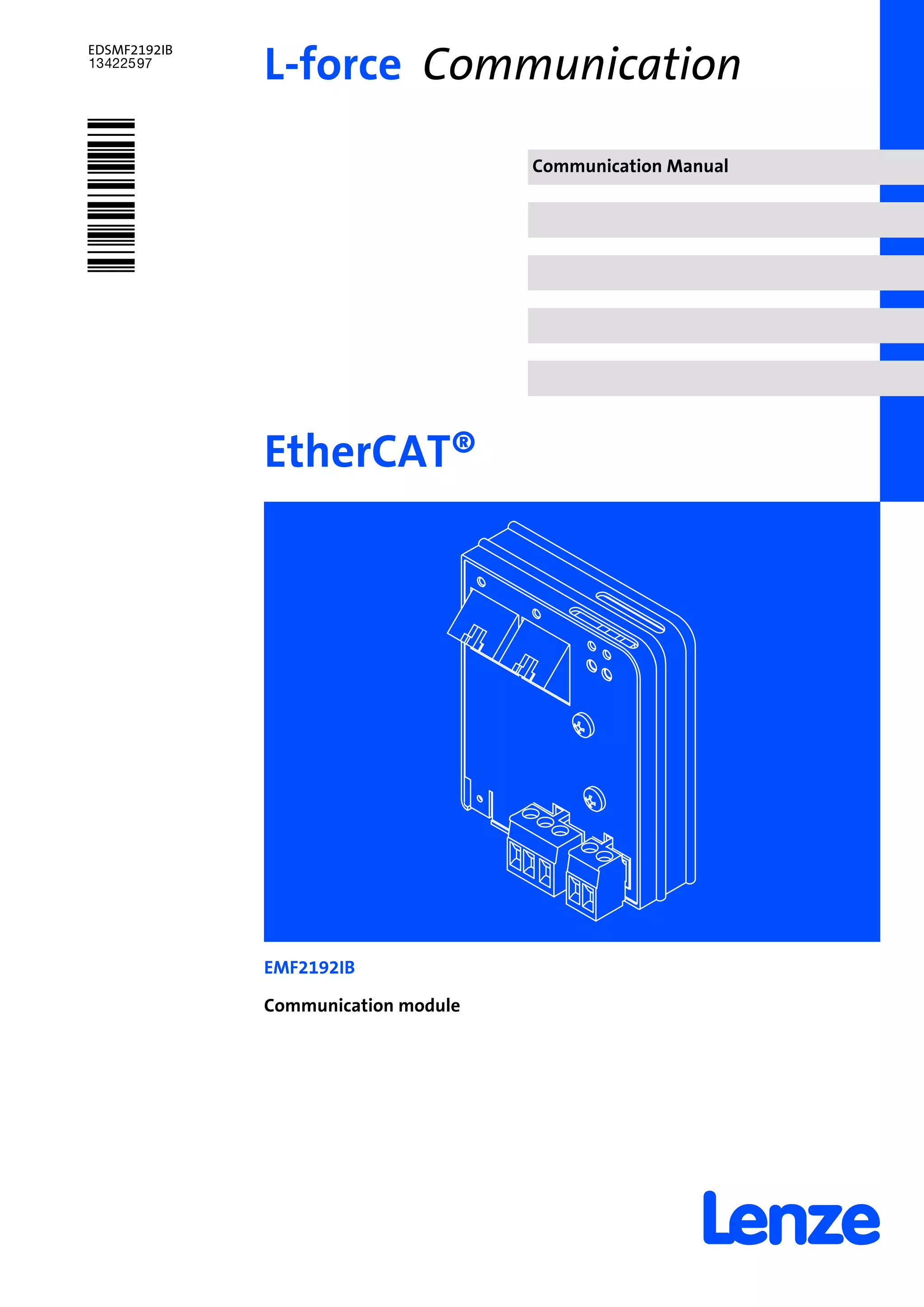
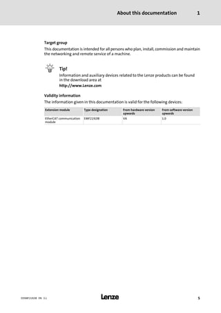
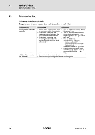
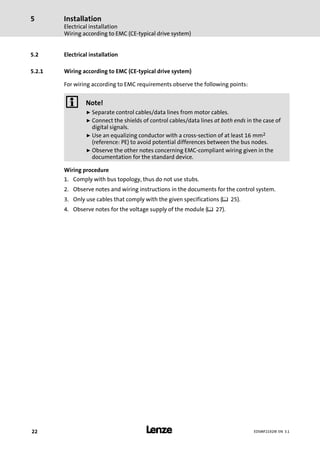
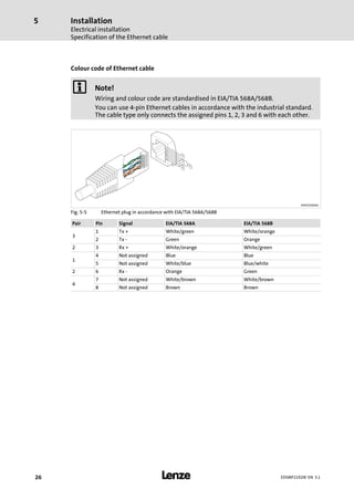
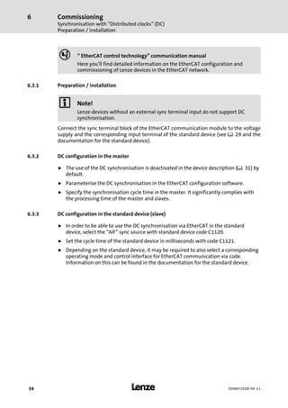
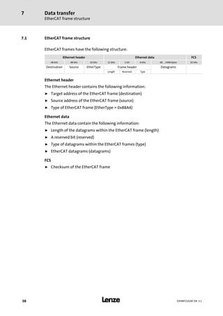
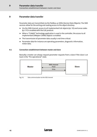
1.2 Conventions used
This documentation uses the following conventions to distinguish between different
types of information:
Type of information Identification Examples/notes
Spelling of numbers
Decimal separator Point In general, the decimal point is used.
For instance: 1234.56
Decimal Standard notation For example: 1234
Hexadecimal 0x[0 ... 9, A ... F] For example: 0x60F4
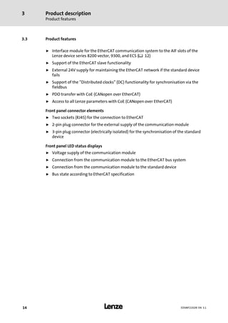
Binary
l Nibble
In quotation marks
Point
For example: ´100´
For example: ´0110.0100´
Text
Program name » « PC software
For example: »Engineer«, »Global Drive
Control« (GDC)
Icons
Page reference ^ Reference to another page with additional
information
For instance: ^ 16 = see page 16](https://image.slidesharecdn.com/emf2192ibethercataifmodulev3-1en-150925161319-lva1-app6891/85/Emf2192-ib-_ethercat-aif-module__v3-1__en-7-320.jpg)

![Parameter data transfer
Reading and writing parameters
Reading parameters (expedited upload)
9
l46 EDSMF2192IB EN 3.1
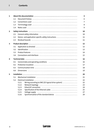
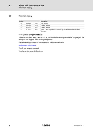
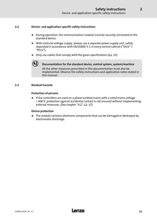
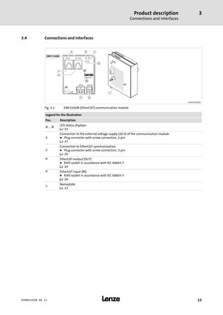
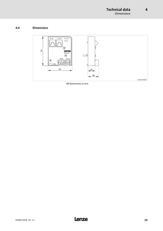
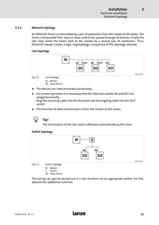
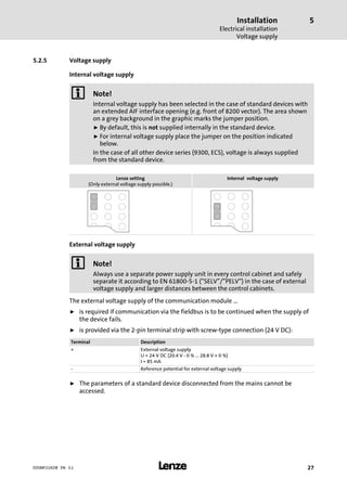
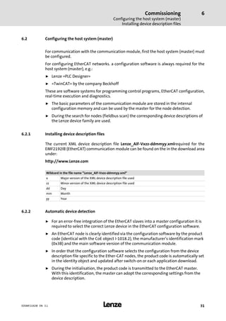
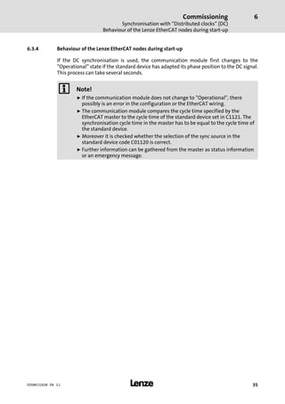
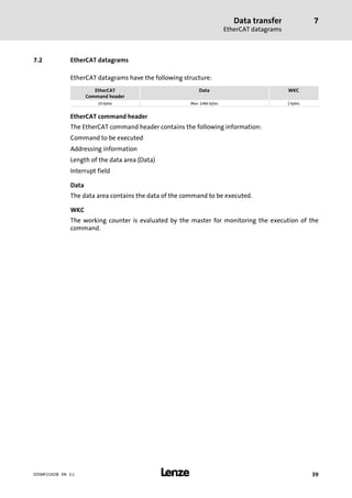
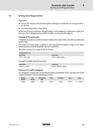
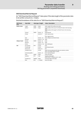
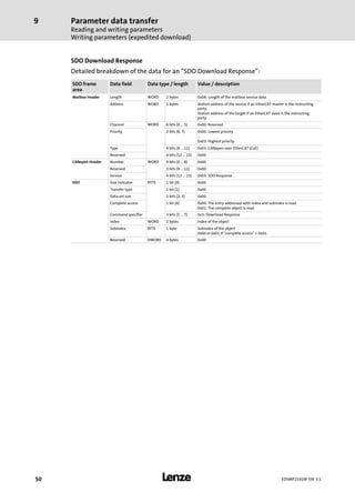
SDO Upload Normal Response
An "SDO Upload Normal" takes place if the data length of the parameter data to be read
amounts to ³ 4 bytes.
Detailed breakdown of the data for an "SDO Upload Normal Response":
SDO frame
area
Data field Data type / length Value [hex] / description
Mailbox Header Length WORD 2 bytes n ³ 0x0A: Length of the mailbox service data
Address WORD 2 bytes Station address of the source if an EtherCAT master is the instructing
party.
Station address of the target if an EtherCAT slave is the instructing
party.
Channel WORD 6 bits (0 ... 5) 0x00: Reserved
Priority 2 bits (6, 7) 0x00: Lowest priority
...
0x03: Highest priority
Type 4 bits (8 ... 11) 0x03: CANopen over EtherCAT (CoE)
Reserved 4 bits (12 ... 15) 0x00
CANopen Header Number WORD 9 bits (0 ... 8) 0x00
Reserved 3 bits (9 ... 11) 0x00
Service 4 bits (12 ... 15) 0x03: SDO Response
SDO Size indicator BYTE 1 bit (0) 0x01
Transfer type 1 bit (1) 0x00: Normal transfer
Data set size 2 bits (2, 3) 0x00
Complete access 1 bit (4) 0x00: The entry addressed with index and subindex is read.
0x01: The complete object is read.
Command specifier 3 bits (5 ... 7) 0x02: Upload Response
Index WORD 2 bytes Index of the object
Subindex BYTE 1 byte Subindex of the object
0x00 or 0x01 if "complete access" = 0x01.
Complete size DWORD 4 bytes Total data length of the object
Data BYTE n − 10 bytes Data of the object](https://image.slidesharecdn.com/emf2192ibethercataifmodulev3-1en-150925161319-lva1-app6891/85/Emf2192-ib-_ethercat-aif-module__v3-1__en-46-320.jpg)
![Parameter data transfer
Reading and writing parameters
Reading parameters (expedited upload)
9
l 47EDSMF2192IB EN 3.1
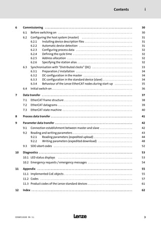
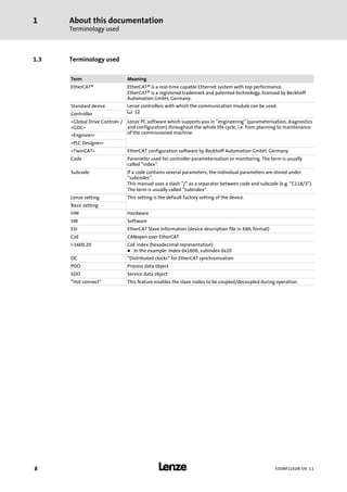
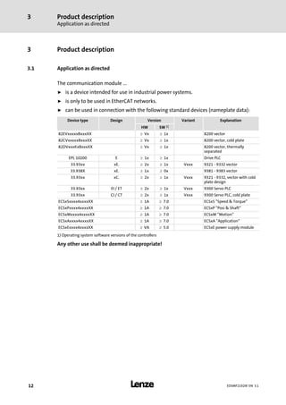
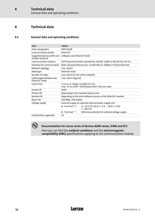
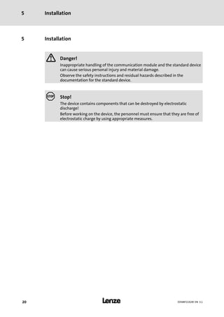
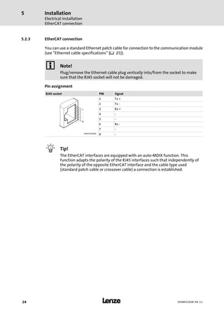
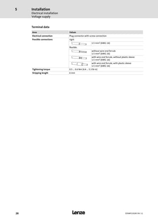
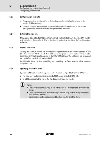
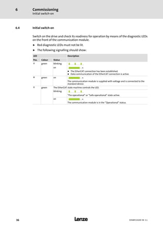
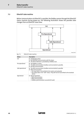
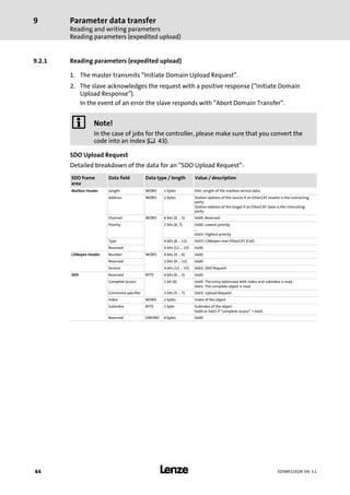
Example
The transmitted response structure in case of an upload to the index 0x5FD8 (standard
value of C00039/1 = 0x0FA0) contains the following data:
SDO frame
area
Data field Data type / length Value [hex] / description
Mailbox Header Length WORD 2 bytes 0x0A: Length of the mailbox service data
Address WORD 2 bytes 0x00
Channel WORD 6 bits (0 ... 5) 0x00: Reserved
Priority 2 bits (6, 7) 0x00: Lowest priority
Type 4 bits (8 ... 11) 0x03: CANopen over EtherCAT (CoE)
Reserved 4 bits (12 ... 15) 0x00
CANopen Header Number WORD 9 bits (0 ... 8) 0x00
Reserved 3 bits (9 ... 11) 0x00
Service 4 bits (12 ... 15) 0x03: SDO Response
SDO Size indicator BYTE 1 bit (0) 0x01: Length of the data in "Data set size"
Transfer type 1 bit (1) 0x01: Expedited transfer
Data set size 2 bits (2, 3) 0x02: 2 bytes data
Complete access 1 bit (4) 0x00: The entry addressed with index and subindex is read.
Command specifier 3 bits (5 ... 7) 0x02: Upload Response
Index WORD 2 bytes 0xD8: Index low byte of the object
0x5F: Index high byte of the object
Subindex BYTE 1 byte 0x01
Data DWORD 2 bytes 0x0FA0](https://image.slidesharecdn.com/emf2192ibethercataifmodulev3-1en-150925161319-lva1-app6891/85/Emf2192-ib-_ethercat-aif-module__v3-1__en-47-320.jpg)
![Parameter data transfer
Reading and writing parameters
Writing parameters (expedited download)
9
l 51EDSMF2192IB EN 3.1
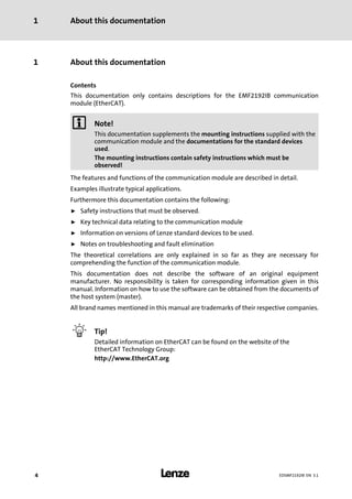
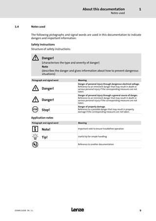
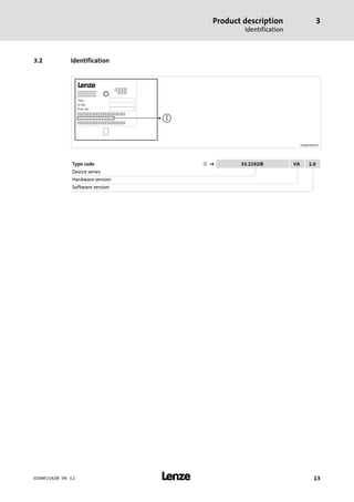
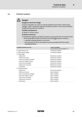
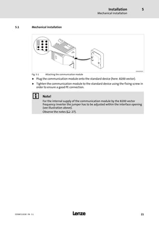
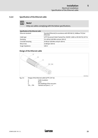
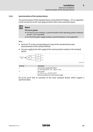
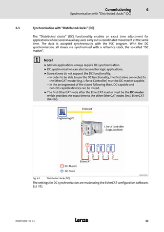
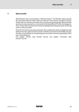
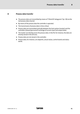
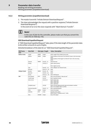
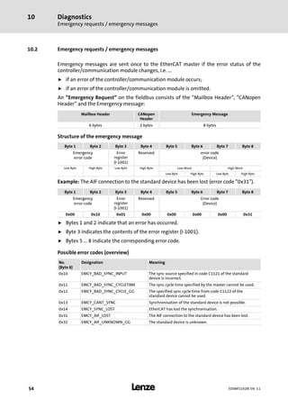
Example
The transmitted request structure in case of a download from the index 0x1600 contains
the following data:
SDO frame
area
Data field Data type / length Value [hex] / description
Mailbox Header Length WORD 2 bytes 0xA: Length of the mailbox service data
Address WORD 2 bytes 0x0
Channel WORD 6 bits (0 ... 5) 0x0: Reserved
Priority 2 bits (6, 7) 0x0: Lowest priority
Type 4 bits (8 ... 11) 0x3: CANopen over EtherCAT (CoE)
Reserved 4 bits (12 ... 15) 0x0
CANopen Header Number WORD 9 bits (0 ...8) 0x0
Reserved 3 bits (9... 11) 0x0
Service 4 bits (12 ... 15) 0x2: SDO request
SDO Size indicator BYTE 1 bit (0) 0x01: Size of the data in "data set size"
Transfer type 1 bit (1) 0x01: Expedited transfer
Data set size 2 bits (2, 3) 0x00: 4 bytes data
Complete access 1 bit (4) 0x00: The entry addressed with index and subindex is written.
Command specifier 3 bits (5 ... 7) 0x01: Download Request
Index WORD 2 bytes 0x00: Index low byte of the object
0x16: Index high byte of the object
Subindex BYTE 1 byte 0x01: Subindex of the object
Data DWORD 4 bytes 0x5C930110](https://image.slidesharecdn.com/emf2192ibethercataifmodulev3-1en-150925161319-lva1-app6891/85/Emf2192-ib-_ethercat-aif-module__v3-1__en-51-320.jpg)
![Parameter data transfer
Reading and writing parameters
SDO abort codes
9
l52 EDSMF2192IB EN 3.1
9.3 SDO abort codes
If an SDO request is evaluated negatively, a corresponding error code is output.
Index [hex] Description
0x00000000 No error
0x05030000 The status of the toggle bit has not changed.
0x05040000 SDO protocol time−out
0x05040001 Invalid or unknown specification symbol for the client/server command
0x05040002 The data block length is too great.
0x05040005 The space in the main memory is not sufficient.
0x06010000 Access to object not supported
0x06010001 Read access to a write−protected object
0x06010002 Write access to a write−protected object
0x06020000 Object is not listed in the object directory.
0x06040041 An object cannot be mapped into the PDO.
0x06040042 The number and/or length of the mapped objects would exceed the PDO length.
0x06040043 General parameter incompatibility
0x06040047 General internal device incompatibility
0x06060000 Access has failed because of hardware errors.
0x06070010 Wrong data type or parameter length.
0x06070012 Incorrect data type (The parameter length is too big)
0x06070013 Wrong data type (parameter length is too small).
0x06090011 Subindex does not exist.
0x06090030 The value range for parameters is too large (only for write access).
0x06090031 The parameter value is too high.
0x06090032 The parameter value is too low.
0x06090036 The maximum value is lower than the minimum value.
0x08000000 General error
0x08000020 Data cannot be transferred to the application or stored in the application.
0x08000021 Due to local control, data cannot be transferred to the application or stored in the
application.
0x08000022 Data cannot be transferred to or saved in the application because of current device state.
0x08000023 Dynamic object directory generation has failed or no object directory available.](https://image.slidesharecdn.com/emf2192ibethercataifmodulev3-1en-150925161319-lva1-app6891/85/Emf2192-ib-_ethercat-aif-module__v3-1__en-52-320.jpg)
![Appendix
Codes
11
l 57EDSMF2192IB EN 3.1
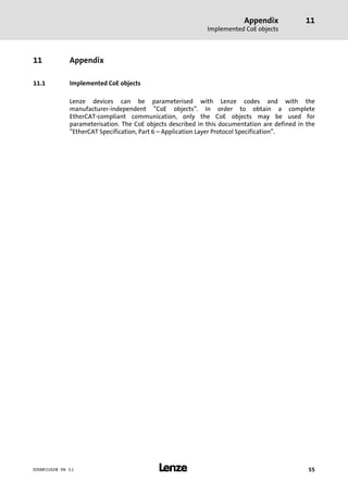
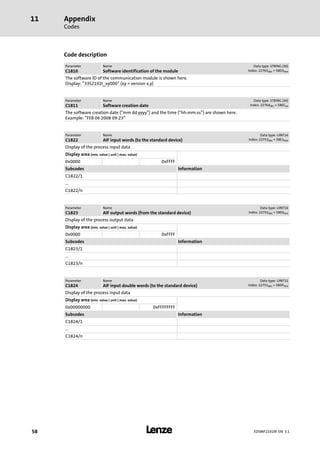
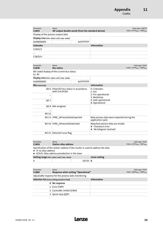
11.2 Codes
The objects specified in the table can be accessed via EtherCAT fieldbus. The objects are
implemented in the Lenze code structure. Writable codes are stored permanently and are
maintained after the communication module is switched off.
I Tip!
The codes are visible in the object directory of the EtherCAT configuration tool.
Object Code Subcode Designation Access Information
Index
[hex]
Subindex
0x58ED − C1810 − Software identification of the module R ^ 58
0x58EC C1811 − Software creation date R ^ 58
0x58E1 1 ... n C1822 1 ... n AIF input words (to the standard device) R ^ 58
0x58E0 1 ... n C1823 1 ... n AIF output words (from the standard device) R ^ 58
0x58DF 1 ... n C1824 1 ... n AIF input double words (to the standard device) R ^ 58
0x58DE 1 ... n C1825 1 ... n AIF output double words (from the standard device) R ^ 59
0x58D9 − C1830 − Bus status R ^ 59
0x58C5 − C1850 − Station alias address RW ^ 59
0x58A5 − C1882 − Response when exiting "Operational" RW ^ 59
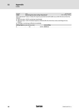
0x58A4 − C1883 − Monitoring time when exiting "Operational" RW ^ 60
R: Read access only
RW: Read and write access](https://image.slidesharecdn.com/emf2192ibethercataifmodulev3-1en-150925161319-lva1-app6891/85/Emf2192-ib-_ethercat-aif-module__v3-1__en-57-320.jpg)
![Appendix
Product codes of the Lenze standard devices
11
l 61EDSMF2192IB EN 3.1
11.3 Product codes of the Lenze standard devices
Product code
[decimal]
Meaning Sync
support
Number
Process data
words
AIF status/
control word
21920000 Generic − − −
21920100 8200 vector − 3 −
21920101 8200 vector
in combination with an application
I/O function module
− 3 −
21920102 8200 vector
in combination with a
DeviceNet/CANopen function
module
− 3 −
21920103 8200 vector
in combination with an INTERBUS
function module
− 3 −
21920104 8200 vector
in combination with a LECOM−B
function module
− 3 −
21920105 8200 vector
in combination with a PROFIBUS I/O
function module
− 3 −
21920106 8200 vector
in combination with a PROFIBUS
function module
− 3 −
21920107 8200 vector
in combination with a CANopen
function module
− 3 −
21920108 8200 vector
in combination with a DeviceNet
function module
− 3 −
21920200 9300 servo inverter ü 4 −
21920202 93xx servo position controller ü 4 −
21920204 93xx servo register control ü 4 −
21920206 93xx servo cam profiler ü 4 −
21920301 9300 hoist − 4 −
21920400 9300 vector − 4 −
21920500 9300 Servo PLC ü 12 ü
21920600 Drive PLC ü 12 ü
21920700 ECSxA axis module "Application" ü 12 ü
21920701 ECSxM axis module "Motion" ü 12 ü
21920702 ECSxP axis module "Posi & Shaft" ü 12 ü
21920703 ECSxS axis module "Speed &
Torque"
ü 12 ü
21920711 ECSxE power supply module − 3 −
) Note!
ECS servo system
From operating system software version 8.3 onwards, a synchronisation is
possible for the ECS axis modules.](https://image.slidesharecdn.com/emf2192ibethercataifmodulev3-1en-150925161319-lva1-app6891/85/Emf2192-ib-_ethercat-aif-module__v3-1__en-61-320.jpg)


This document provides information about an EtherCAT communication module used for networking and remote servicing of machines. It describes the features and functions of the communication module, including safety instructions. It also provides technical specifications and information about configuration, installation, commissioning, and data transfer processes. The document is intended to supplement other documentation for standard devices and provide details on using the communication module with a host system over EtherCAT.


