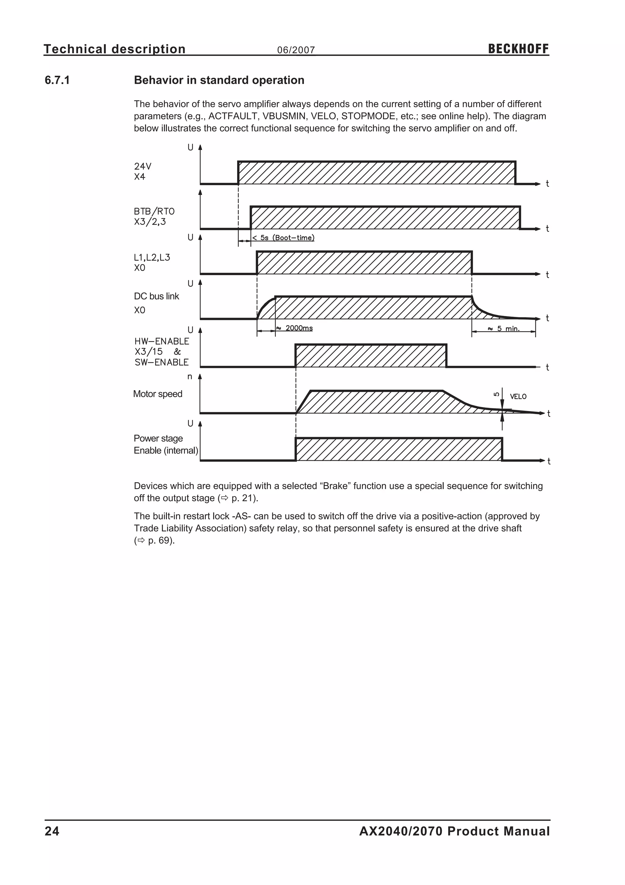
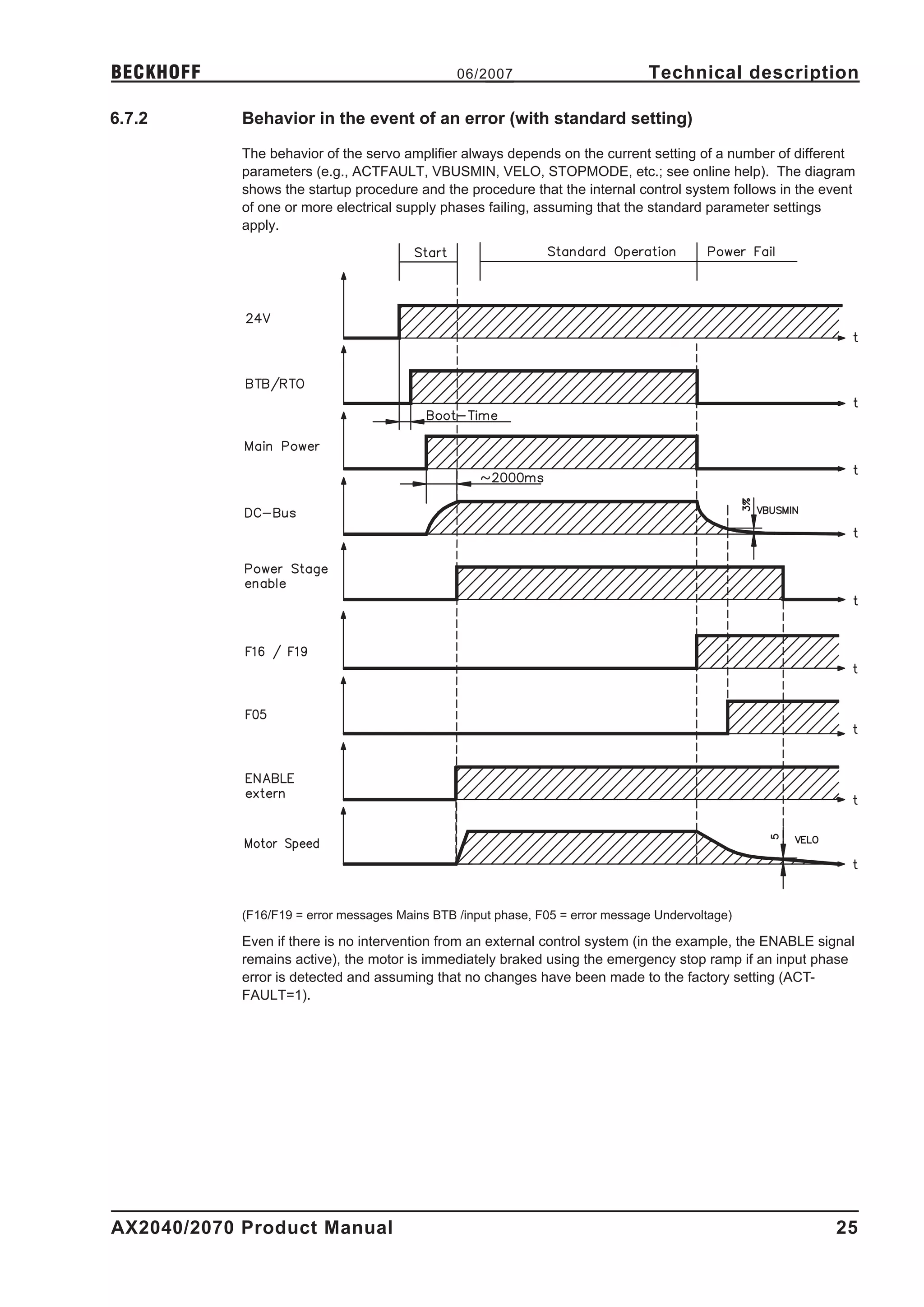
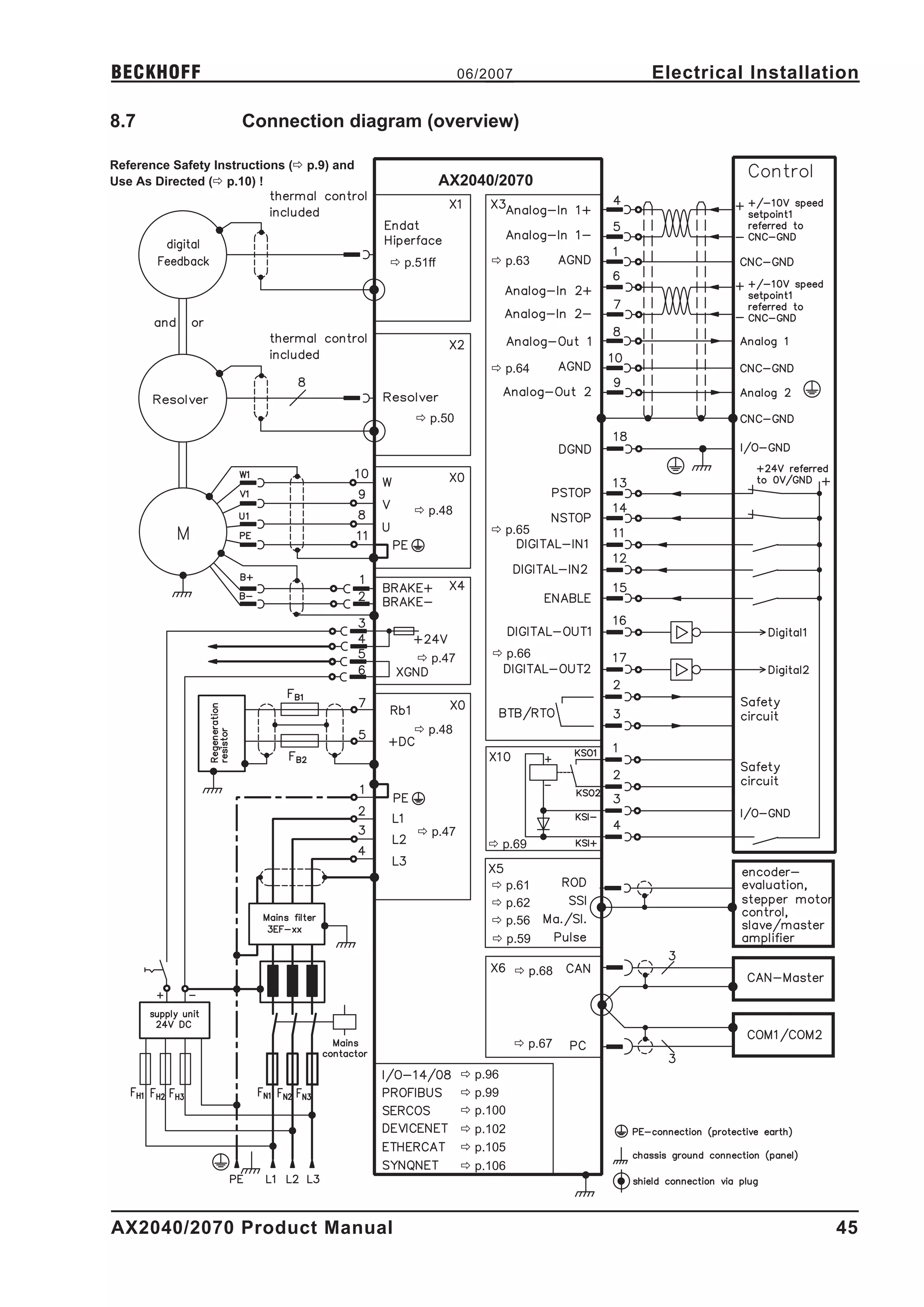
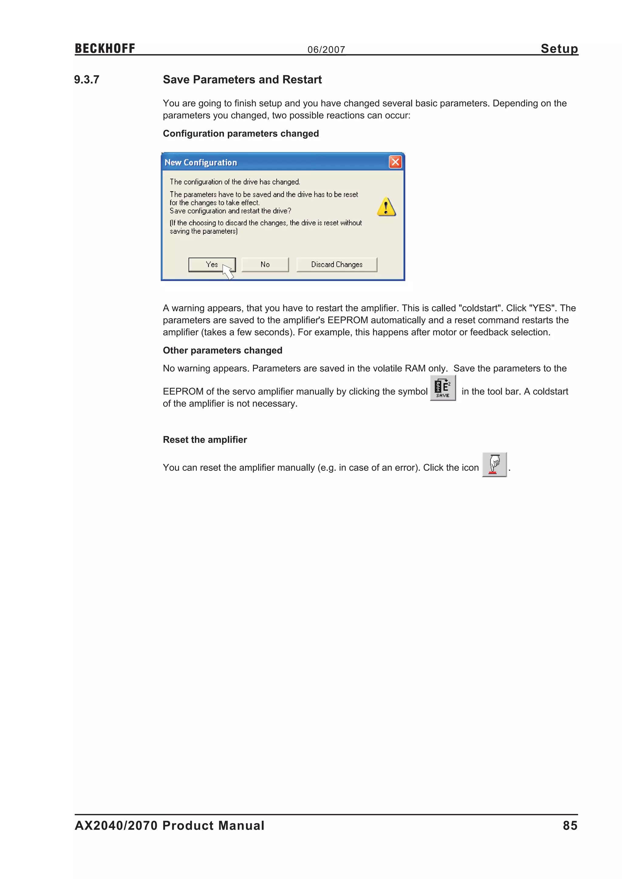
This document provides information about the installation, setup, safety, technical description, and specifications of the AX2040/2070 digital servo amplifier. It discusses keeping and passing along all product manuals, standards and approvals that apply, packaging and handling, the components included, technical details of the device, installation and setup instructions, and safety precautions including shock hazard protection.
![Safety 06/2007 BECKHOFF
2.2 Use as directed
l The servo amplifiers are components which are built into electrical equipment or machines,
and can only be used as integral components of such equipment.
l The manufacturer of the machine must generate a hazard analysis for the machine, and
take appropriate measures to ensure that unforeseen movements cannot cause injury or
damage to any person or property.
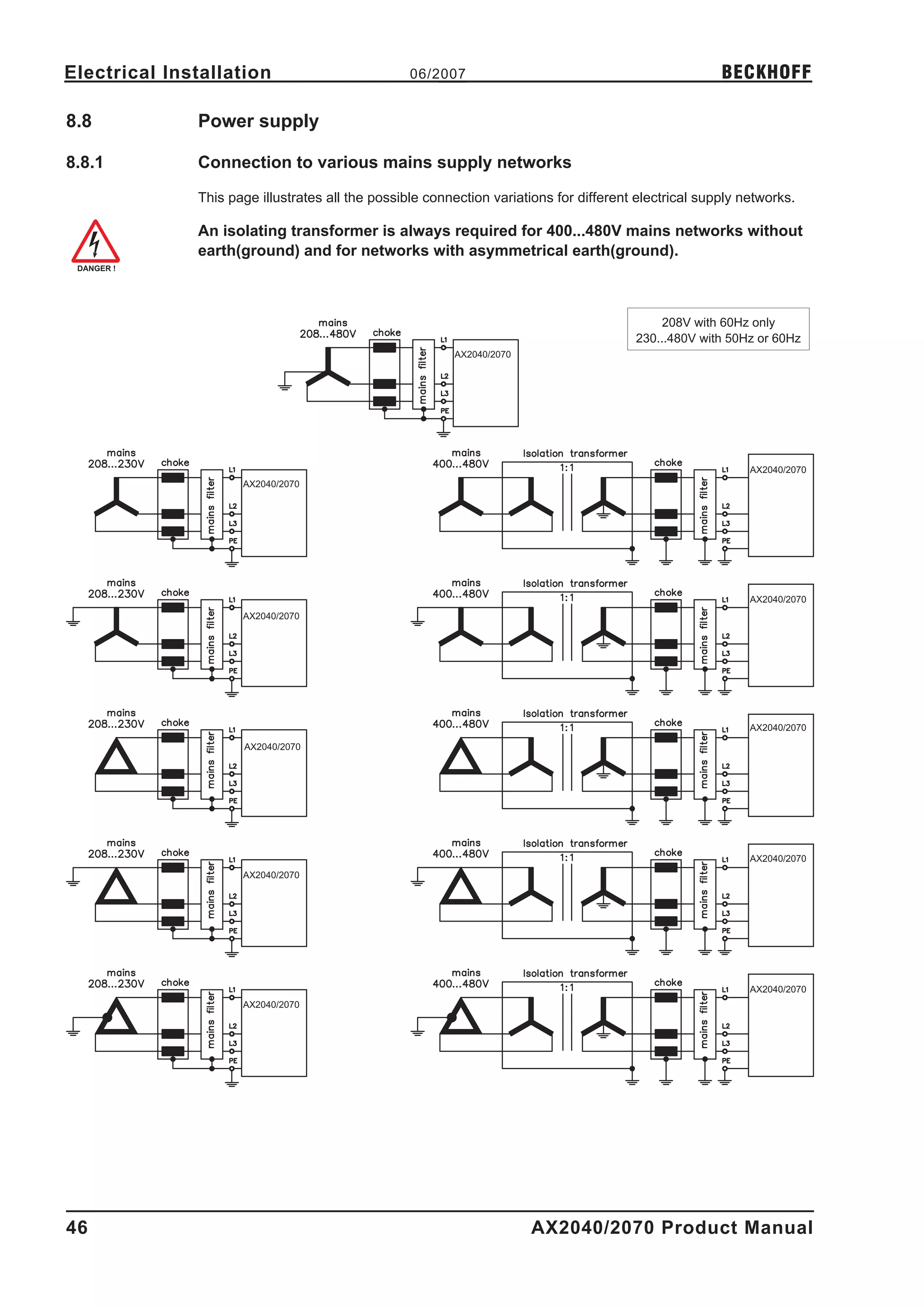
l The AX2040/2070 family of servo amplifiers can be connected directly to symmetrically eart-
hed(grounded) three-phase industrial mains supply networks [TN-system, TT-system with
earthed(grounded) neutral point, not more than 5000rms symmetrical amperes, 480VAC
maximum] when protected by fuses type Fusetron FRS-R-50 for AX20 640 or FRS-R-80
class RK5 for AX20 670, manufactured by Bussman, or equivalent, 480VAC min.
The use of external mains chokes and mains filters is required.
l The servo amplifiers must not be operated directly on power supply networks >230V without
an earth (ground) or with an asymmetrical earth (ground).
Connection to other mains supply networks ð p. 46.
l Periodic overvoltages between outer conductor (L1, L2, L3) and housing of the servo ampli-
fier may not exceed 1000V (peak value).
Transient overvoltages (< 50µs) between the outer conductors may not exceed 1000V.
Transient overvoltages (< 50µs) between outer conductors and housing may not exceed
2000V.
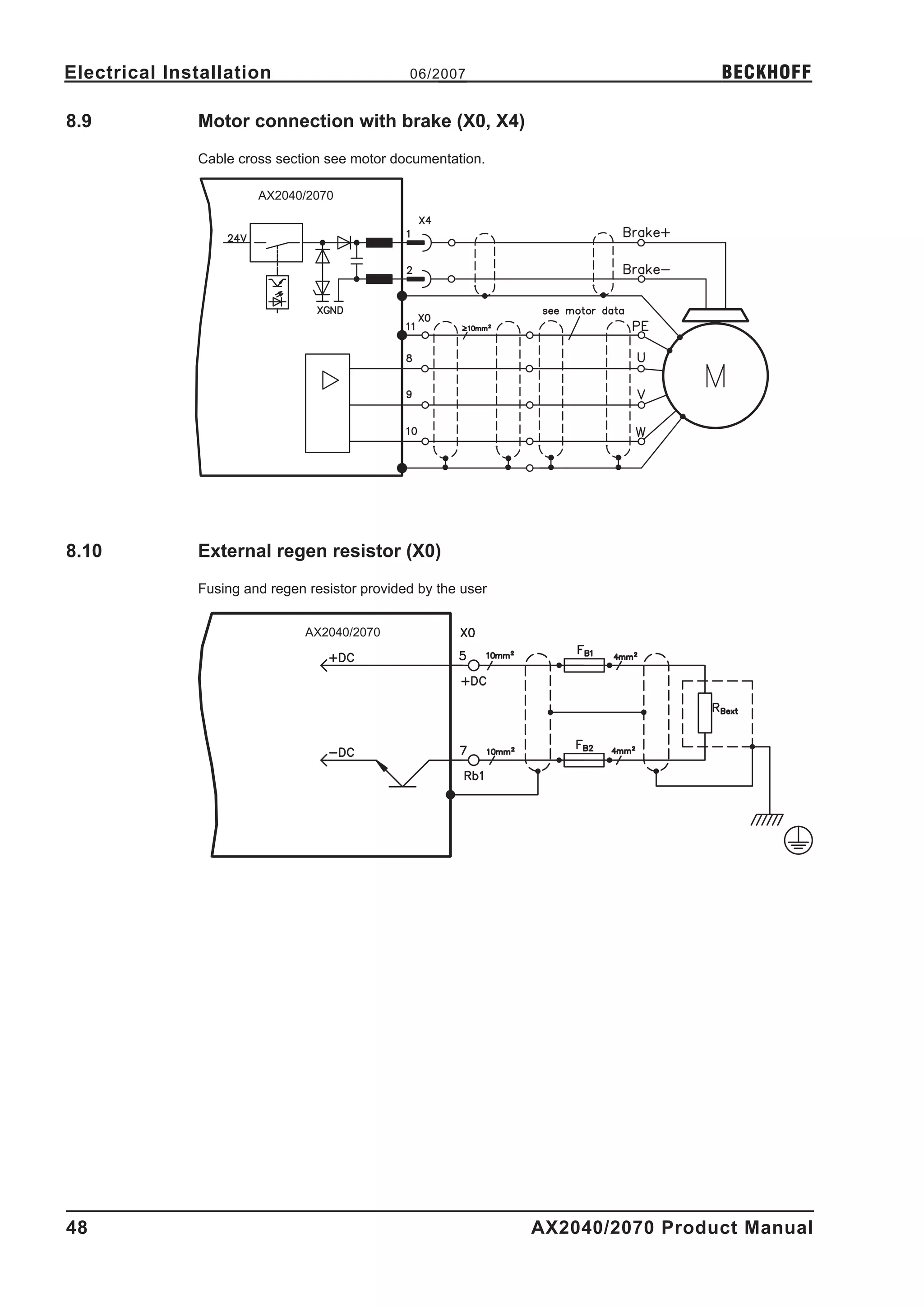
l The regen resistors have to be protected by fuses type Limitron KLM, rated for 500VAC/DC
l The AX2040/2070 family of servo amplifiers is only intended to drive specific brushless syn-
chronous servomotors with closed-loop control of torque, speed and/or position. The rated
voltage of the motors must be at least as high as the DC bus link voltage of the servo ampli-
fier. The motor must have integral thermal protection.
l The servo amplifiers may only be operated in a closed switchgear cabinet, taking into
account the ambient conditions defined on page 19 and the dimensions shown on page 34.
Ventilation or cooling may be necessary to prevent enclosure ambient from exceeding 45°C
(113°F).
l Use copper wire only. Wire size may be determined from EN 60204 (or table 310-16 of the
NEC 60°C or 75°C column for AWG size).
l We only guarantee the conformance of the servo amplifiers with the standards for industrial
areas (page 11), if the components are delivered by BECKHOFF.
l Consider the specifications on page 70 when you use the personnel safe restart lock -AS-.
10 AX2040/2070 Product Manual](https://image.slidesharecdn.com/ax2040en-111001073903-phpapp02/75/Ax2040-en-10-2048.jpg)


![Setup 06/2007 BECKHOFF
9.3.8 Jogging the Motor (Speed Control)
Be aware that the actual position of the load permits the subsequent moving
operations. The axis could move to the hardware limit-switch or the mechanical
stop. Make sure that a jerk or a fast acceleration of the load cannot cause any
damage.
l Switch on the power supply for the drive.
l Hardware-Enable: +24 VDC to Enable [connector X3 pin 15].
l Software-Enable: Click the "Enable" button on the start screen or use key
combination Shift+F12. Now, the front display shows an E and the current rating (e.g.
for Enable, 40 amps)
l Click the icon "Oscilloscope"
l Select Service-Mode "Speed F6", then click "Parameter" button
l Enter a safe speed. The sign defines the direction of movement.
Observe the "safe reduced speed" requirements for your application!
l Click OK.
l Start the service function ("Start" button or press F6).
Click OK on the warning notice.
Opmode is switched to "0" and the output stage is enabled automatically. The symbol's color
changes to green as long as the function is active.
l The function is active until you click the "Stop" button or press F9.
l The output stage can be disabled by pressing function key F12.
86 AX2040/2070 Product Manual](https://image.slidesharecdn.com/ax2040en-111001073903-phpapp02/75/Ax2040-en-86-2048.jpg)