This document provides a user's manual for the GE Model PM880 Portable Hygrometer. It contains instructions for setup, operation and maintenance of the device. The manual includes directions for charging the battery, powering on/off, entering data, taking measurements, using the display screen and special features. Safety warnings are also provided regarding working with auxiliary equipment and ensuring proper personnel qualifications.


![Contents
[no content intended for this page]
xii Model PM880 Portable Hygrometer User’s Manual](https://image.slidesharecdn.com/910-247flr-1-110719060037-phpapp02/85/910-247-f-lr-1-14-320.jpg)


![Chapter 1. Getting Started
1.2 Powering On and Off
IMPORTANT: For CE compliance, the PM880 is classified as a
battery-powered device.
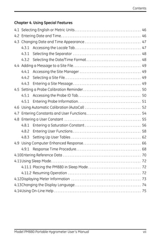
1.2.1 Powering On
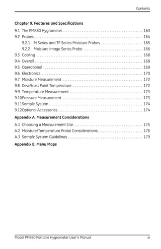
To turn the PM880 on, press the red button in the upper-right-hand corner of
the keypad. Immediately upon powerup the PM880 displays a series of
messages and performs various checks. The screen then appears similar to
the one shown in Figure 1.
Note: If the meter displays a Probe Reminder message, press [ENTER].
Figure 1: Screen After Powering On
Note: If the meter fails any of these tests, contact the factory.
Model PM880 Portable Hygrometer User’s Manual 5](https://image.slidesharecdn.com/910-247flr-1-110719060037-phpapp02/85/910-247-f-lr-1-19-320.jpg)
![Chapter 1. Getting Started
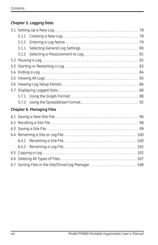
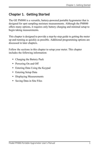
1.2.2 Powering Off
1. To turn the PM880 off, press the red key for 3 seconds. The screen now
appears similar to Figure 2.
2. Press [F1] to shut down the PM880.
Figure 2: Shutdown Menu
6 Model PM880 Portable Hygrometer User’s Manual](https://image.slidesharecdn.com/910-247flr-1-110719060037-phpapp02/85/910-247-f-lr-1-20-320.jpg)
![Chapter 1. Getting Started
1.3 Entering Data Using the Keypad
Use the information below to familiarize yourself with how to enter data
using the PM880 keypad.
Use the arrow keys to scroll to a menu topic and then press [ENTER] to open
the menu.
When entering data into a menu window, press:
• The [] key to scroll forward through the menu options.
• The [] key to scroll back through menu options.
• The [F2] key (Cancel) or the [ESC] key to exit a menu at any time and
return to Operate Mode without changing data.
Note: If you enter an incorrect numeric value, press the [] key to erase
the last digit entered.
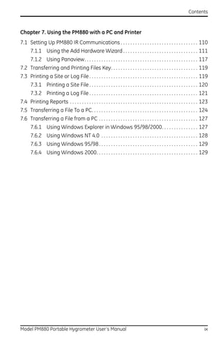
1.4 Entering Setup Data
For immediate operation, the PM880 requires only a moisture probe and its
corresponding calibration data. You should enter data for each site where
you plan to make a measurement. Once entered, you can save it into a file
that can be recalled at the measurement site. Use the sections that follow to
program your meter.
Note: The PM880 has additional menus that enable you to tailor
measurements as specifically as possible to your particular
application. For more information on menu options refer to
Chapter 4, Using Special Features.
Model PM880 Portable Hygrometer User’s Manual 7](https://image.slidesharecdn.com/910-247flr-1-110719060037-phpapp02/85/910-247-f-lr-1-21-320.jpg)
![Chapter 1. Getting Started
1.4.1 Selecting Probe Type
Use the steps below to select the probe type for the measurement site. Refer
to Figure 9 on page 19 for a menu map.
Note: You may also enter a constant value (rather than a live input) for
moisture, temperature or pressure measurement. For more
information refer to Entering Constants and User Functions on
page 54.
1. If the menu is not active, press [MENU].
2. Use the arrow key to scroll to Program and press [ENTER].
3. Use the arrow key to scroll to Probe and press [ENTER]. The screen
appears similar to Figure 3.
Figure 3: Probe Window
8 Model PM880 Portable Hygrometer User’s Manual](https://image.slidesharecdn.com/910-247flr-1-110719060037-phpapp02/85/910-247-f-lr-1-22-320.jpg)
![Chapter 1. Getting Started
1.4.1 Selecting Probe Type (cont.)
4. At Type, press [ENTER] to open the drop-down list of probe types.
Note: If you do not know the probe type, refer to the Calibration Data
Sheet.
5. Use the arrow keys to scroll to the desired selection and press [ENTER].
6. Press [F3] (OK) to exit.
Next, do one of the following:
• If you are using an M or TF Series probe, proceed to Entering
Calibration Data on the next page.
• If you are using an MIS or an MISP2 Probe, proceed to Displaying
Measurements on page 15.
Note: If you have an MIS probe that was sent back to the factory for
calibration without the electronics module, you need to enter
calibration data as described in Entering Calibration Data on
page 10.
Model PM880 Portable Hygrometer User’s Manual 9](https://image.slidesharecdn.com/910-247flr-1-110719060037-phpapp02/85/910-247-f-lr-1-23-320.jpg)
![Chapter 1. Getting Started
1.4.2a Entering Probe ID
1. If the menu is not active, press [MENU].
2. Use the arrow key to scroll to Program and press [ENTER].
3. Use the arrow key to scroll to Calibrate and press [ENTER].
4. Use the arrow keys to scroll to the Probe ID tab and press [ENTER]. A
screen similar to Figure 4 appears.
Figure 4: Probe ID Window
5. Use the arrow keys to scroll to S/N and press [ENTER].
6. Use the numeric keys to enter the serial number from the Calibration
Data Sheet and press [ENTER]. The serial number also appears on the
hex nut of the moisture probe.
7. Use the arrow keys to scroll to the suffix box and press [ENTER] to open
the drop-down list.
8. Use the arrow keys to scroll to the desired suffix and press [ENTER].
9. Press [F3] (OK) to exit.
Model PM880 Portable Hygrometer User’s Manual 11](https://image.slidesharecdn.com/910-247flr-1-110719060037-phpapp02/85/910-247-f-lr-1-25-320.jpg)
![Chapter 1. Getting Started
1.4.2b Entering Moisture Calibration Data
You need to enter calibration data for M and TF Series probes only. The
Moisture Image Series (MIS) probes store all calibration data in their
electronics module, and upload it into the PM880 memory when needed.
Note: It is not necessary to enter calibration data for the Moisture Image
Series (MIS) probe unless you send it back to the factory for
calibration without its electronics module. If this is the case, you
must manually enter the calibration data as described below.
Note: It is not necessary to enter calibration data for the MISP2 probe.
Enter moisture calibration data (MH or FH) and dewpoint readings (up to
20 data points) for the moisture probe as described below. Refer to Figure 9
on page 19 for a menu map.
Note: If you are using an MIS probe and do not need to enter data, proceed
to Displaying Measurements on page 15.
1. If the menu is not active, press [MENU].
2. Use the arrow key to scroll to Program and press [ENTER].
3. Use the arrow key to scroll to Calibrate and press [ENTER].
4. If necessary, use the arrow key to scroll to Hygro and press [ENTER]. A
screen appears similar to Figure 5 on page 13.
5. Press [] to move the pointer to the 00/MH box in the calibration table.
6. Press [ENTER] to change the value. Use the numeric keys to enter the
desired MH or FH value, and press [ENTER].
12 Model PM880 Portable Hygrometer User’s Manual](https://image.slidesharecdn.com/910-247flr-1-110719060037-phpapp02/85/910-247-f-lr-1-26-320.jpg)
![Chapter 1. Getting Started
1.4.2b Entering Moisture Calibration Data (cont.)
Figure 5: Hygro Window in Calibration
7. Press [] to move to the next text box, and press [ENTER]. Use the
numeric keys to enter the corresponding dewpoint reading and press
[ENTER].
8. Use the arrow keys to scroll to additional data points and repeat steps 5,
6 and 7 until you have entered the values for each data point.
Note: To insert an additional data point, press [F1] (Insert).
To delete a data point, press [F2] (Delete).
9. When you have completed entering values, press [F3] (EXIT).
Next, do one of the following:
• If the probe has a pressure transducer, proceed to step 3 in Entering
Pressure Calibration Data on page 14.
• If the probe does not have a pressure transducer, press [F3] (OK).
Proceed to Displaying Measurements on page 15.
Model PM880 Portable Hygrometer User’s Manual 13](https://image.slidesharecdn.com/910-247flr-1-110719060037-phpapp02/85/910-247-f-lr-1-27-320.jpg)
![Chapter 1. Getting Started
1.4.2c Entering Pressure Calibration Data
To enter calibration data for the pressure transducer, you must list the zero
and span range in mV (or FP) and psig. Refer to Figure 9 on page 19 for a
menu map.
1. If the menu is not active, press [MENU].
2. Use the arrow key to scroll to Program and press [ENTER].
3. Use the arrow key to scroll to Calibrate and press [ENTER].
4. Use the arrow key to scroll to Pressure and press [ENTER]. The screen
appears similar to Figure 6.
Note: The corresponding mV value can be in psig (English) or kPa
(metric). The supplied Calibration Data Sheets list these values in
psig. If you want to change the system units, refer to Selecting
English or Metric Units on page 46.
Figure 6: Calibration Pressure Window
14 Model PM880 Portable Hygrometer User’s Manual](https://image.slidesharecdn.com/910-247flr-1-110719060037-phpapp02/85/910-247-f-lr-1-28-320.jpg)
![Chapter 1. Getting Started
1.4.2c Entering Pressure Calibration Data (cont.)
5. Press [] to move the pointer to the Zero/mV (Zero/FP) box in the
table.
6. Press [ENTER] to change the value. Use the numeric keys to enter the
desired value and press [ENTER].
7. The corresponding pressure value box is highlighted. Use the numeric
keys to enter the corresponding pressure value and press [ENTER].
8. The span mV box is highlighted. Repeat steps 5, 6 and 7 to enter the
Span values.
9. When you have completed entering values, press [F3] (Exit).
10. Press [F3] (OK) and proceed to Displaying Measurements.
1.5 Displaying Measurements
The PM880 can display one to four measurement parameters
simultaneously. There are two parts for displaying measurements: selecting
the number of measurements and then selecting the type of measurements.
See Figure 9 on page 19 for a menu map.
1.5.1 Selecting the Number of Measurements
1. If the menu is not active, press [MENU].
2. Use the arrow keys to scroll to Site and press [ENTER].
3. Use the arrow keys to move to the desired number of views or
measurement windows (1 View, 2 Views, etc.).
4. Press [ENTER] at your selection. The screen displays the designated
number of views (measurement windows).
Model PM880 Portable Hygrometer User’s Manual 15](https://image.slidesharecdn.com/910-247flr-1-110719060037-phpapp02/85/910-247-f-lr-1-29-320.jpg)
![Chapter 1. Getting Started
1.5.2 Selecting the Types of Measurements
1. Press [SEL] or arrow keys to move the pointer to the window you want to
change and press [ENTER].
2. Use the arrow keys to scroll to Measurement and press [ENTER]. The
screen appears similar to Figure 7. The left column displays the five
measurement types and the right column displays the measurement
units.
Figure 7: Select Measurement Window
3. Use the arrow keys to scroll to the desired measurement type and press
[SEL].
4. Use the arrow keys to select the desired measurement unit (or diagnostic
parameter).
Note: Press [F3] (No Unit) to display a measurement with no units.
5. Press [F3] (OK).
6. Repeat this section for displaying other measurements.
16 Model PM880 Portable Hygrometer User’s Manual](https://image.slidesharecdn.com/910-247flr-1-110719060037-phpapp02/85/910-247-f-lr-1-30-320.jpg)
![Chapter 1. Getting Started
1.6 Saving Data in a Site File
A site file contains probe ID, calibration data and display setup information
in a file so it can be recalled at the measurement site. Use the following
steps to store the data you have entered into a file (see Figure 9 on page 19
for a menu map):
1.6.1 Accessing the Site Manager
1. If the menu is not active, press [MENU].
2. Use the arrow key to scroll to Site and press [ENTER].
3. Use the arrow key to scroll to Site Manager and press [ENTER].
4. Press [MENU].
5. Use the arrow key to scroll to File and press [ENTER].
1.6.2 Entering a Site Name
1. Use the arrow keys to scroll to New and press [ENTER]. The screen
appears similar to Figure 8.
Figure 8: New Site Name Entry Window
Model PM880 Portable Hygrometer User’s Manual 17](https://image.slidesharecdn.com/910-247flr-1-110719060037-phpapp02/85/910-247-f-lr-1-31-320.jpg)
![Chapter 1. Getting Started
1.6.2 Entering a Site Name (cont.)
2. The PM880 displays a default name for the file. If you want to keep the
default name, skip to step 4. Otherwise, use [F1] to erase the name and
use the arrow keys to scroll to the desired letter or number and press
[ENTER].
3. Repeat this procedure until you have created the desired site name of up
to eight characters.
4. When you have finished, press [F3] (OK).
5. The PM880 prompts you to save the site file as a template. This is useful
if you need to create multiple sites with similar data. At the prompt, do
one of the following:
• Press [F2] (No) if you do not need to use a template, or
• Press [F3] (Yes) if you do want to use it as a template.
Note: If you are saving a new file as a template, the PM880 will ask if you
want to Save Current Site, press [F2] (No) or [F3] (Yes).
6. Press [F3] (Exit).
7. Press [MENU]. The new site name is displayed in the upper left corner of
the screen. You have completed entering site data.
Next, do one of the following:
• If you are done entering site data, proceed to the next chapter, Taking
Measurements.
• If you need to enter information for another site, go back to Entering
Setup Data on page 7.
Note: If you need to create multiple site files with similar data, you can
save time by creating one site file and then using Save As in the Site
Manager to create a copy of that site file with a different name.
Refer to Renaming a Site File on page 100.
18 Model PM880 Portable Hygrometer User’s Manual](https://image.slidesharecdn.com/910-247flr-1-110719060037-phpapp02/85/910-247-f-lr-1-32-320.jpg)
![Chapter 1. Getting Started
Menu
Program Site
Manager Save 1 View 2 Views 3 Views 4 Views
Probe Calibrate
M2 M2T TF MISP None
Hygro Pressure Probe ID File
Zero FP
S/N
Hygro Constant MH (FH) New
Zero kPa
Dew Point
Temperature Constant Span FP
Name
Pressure Constant Span kPa
Note: Press [F2] (Cancel) to cancel the entries and return to Menu.
Press [F3] (OK) to confirm the entries and return to Menu.
Figure 9: Startup Menu
Model PM880 Portable Hygrometer User’s Manual 19](https://image.slidesharecdn.com/910-247flr-1-110719060037-phpapp02/85/910-247-f-lr-1-33-320.jpg)
![Chapter 1. Getting Started
[no content intended for this page]
Model PM880 Portable Hygrometer User’s Manual 20](https://image.slidesharecdn.com/910-247flr-1-110719060037-phpapp02/85/910-247-f-lr-1-34-320.jpg)
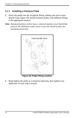
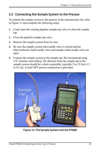
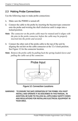
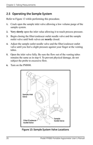
![Chapter 2. Taking Measurements
2.4 Recalling a Site File
To begin taking measurements you must recall the site file that contains data
for the measurement site where you want to take measurements.
2.4.1 Accessing the Site Manager
1. If the menu is not active, press [MENU].
2. Use the arrow key to scroll to Site and press [ENTER].
3. Use the arrow key to scroll to Site Manager and press [ENTER].
2.4.2 Retrieving the Site File
1. Use the arrow key to scroll to the desired site and press [MENU].
2. Use the arrow key to scroll to File and press [ENTER].
3. Use the arrow key to scroll to Open and press [ENTER].
4. The PM880 asks you to confirm, press [F3] (Yes).
5. Press [F3] (Exit).
6. Press [MENU]. The PM880 displays the selected site file in the
upper-left corner of the screen.
Model PM880 Portable Hygrometer User’s Manual 25](https://image.slidesharecdn.com/910-247flr-1-110719060037-phpapp02/85/910-247-f-lr-1-39-320.jpg)


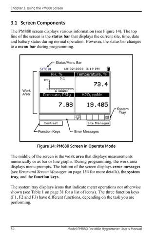
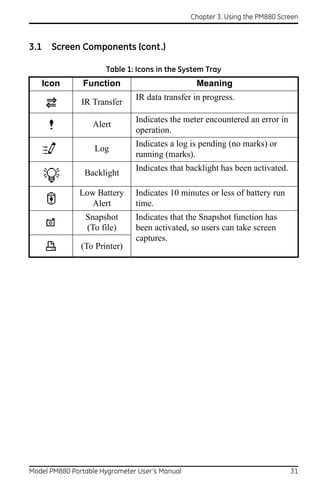
![Chapter 3. Using the PM880 Screen
3.2 Setting Up the Screen to Display Measurements
The PM880 can display one to four measurements simultaneously. After
you select how many measurements to display, you can select the type of
measurements (dewpoint, temperature, etc.) and the format (numeric, line
or bar graph). In addition, the PM880 offers various options for displaying
data numerically and graphically.
This section consists of the following:
• Selecting the Number of Views (Measurements) - page 32
• Selecting the Types of Measurements - page 33
• Selecting Numeric, Line or Bar Graph Format - page 34
• Setting Up the Numeric Format - page 34
• Adjusting the Line/Bar Graph Scale - page 36
Use the section(s) that follow to set up the PM880 screen.
3.2.1 Selecting the Number of Views (Measurements)
1. If the menu is not active, press [MENU].
2. Use the arrow keys to scroll to Site and press [ENTER].
3. Use the arrow keys to move to the desired number of views or
measurement windows (1 View, 2 Views, etc.).
4. Press [ENTER] at your selection. The screen displays the designated
number of views (measurement windows).
32 Model PM880 Portable Hygrometer User’s Manual](https://image.slidesharecdn.com/910-247flr-1-110719060037-phpapp02/85/910-247-f-lr-1-46-320.jpg)
![Chapter 3. Using the PM880 Screen
3.2.2 Selecting the Types of Measurements
1. Press [SEL] to move the pointer to the window you want to change and
press [ENTER].
2. Use the arrow keys to scroll to Measurement and press [ENTER]. The
screen appears similar to Figure 15. The left column displays the five
measurement types and the right column displays the measurement
units.
3. Use the arrow keys to scroll to the desired measurement type and press
[SEL].
4. Use the arrow keys to select the desired measurement unit (or
diagnostic parameter).
Note: Press [F3] (No Unit) to display a measurement with no units.
5. Press [F3] (OK).
6. Repeat this section for displaying other measurements.
Figure 15: Select Measurement Window
Model PM880 Portable Hygrometer User’s Manual 33](https://image.slidesharecdn.com/910-247flr-1-110719060037-phpapp02/85/910-247-f-lr-1-47-320.jpg)
![Chapter 3. Using the PM880 Screen
3.2.3 Selecting Numeric, Line or Bar Graph Format
1. Press [SEL] to move the pointer to the window you want to change and
press [ENTER].
2. Use the arrow keys to scroll to View and press [ENTER].
3. Use the arrow keys to select the desired format and press [ENTER].
The PM880 displays the desired format and returns to taking measurements.
3.2.4 Setting Up the Numeric Format
1. Press [SEL] to move the pointer to the window you want to change and
press [ENTER].
2. Use the arrow keys to scroll to Format and press [ENTER]. The screen
appears similar to Figure 16.
Note: If FORMAT does not appear in the menu, move to a window that is
not displaying a line or bar graph, or change the window format to
numeric as described in the previous section.
Figure 16: Number Format Window
34 Model PM880 Portable Hygrometer User’s Manual](https://image.slidesharecdn.com/910-247flr-1-110719060037-phpapp02/85/910-247-f-lr-1-48-320.jpg)
![Chapter 3. Using the PM880 Screen
3.2.4 Setting Up the Numeric Format (cont.)
3. Use the arrow keys to scroll to Format and press [ENTER].
4. Use the arrow keys to select the desired selection and press [ENTER].
You can select from the following:
• Default - displays the factory default number of decimal digits for the
selected measurement.
• Fixed Decimal - specifies how many digits are to the right of the
decimal.
• Scientific format - displays the value in mantissa exponent format
(expressed to the power of 10).
5. Repeat steps 3 and 4 for Decimal Places or proceed to the next step to
exit. You can select from 0 to 4 places.
6. Press [F3] (OK). The PM880 displays the new format and resumes
taking measurements.
Model PM880 Portable Hygrometer User’s Manual 35](https://image.slidesharecdn.com/910-247flr-1-110719060037-phpapp02/85/910-247-f-lr-1-49-320.jpg)
![Chapter 3. Using the PM880 Screen
3.2.5 Adjusting the Line/Bar Graph Scale
The scale of the line and bar graph can be adjusted at any time. You can also
alter the graph to display details as follows:
1. Press [SEL] to move the pointer to the window you want to change and
press [ENTER].
2. Use the arrow keys to scroll to Limits and press [ENTER]. A screen
similar to Figure 17 appears
Figure 17: Line Graph Parameters Window
3. Use the arrow keys to scroll to Minimum and press [ENTER].
4. Use the numeric keys to enter the minimum value for the graph and
press [ENTER].
5. Repeat steps 3 and 4 for the maximum value.
6. Do one of the following:
• If you are using a line graph, proceed to step 7.
• If you are using a bar graph, proceed to step 10.
7. Use the arrow keys to scroll to the time interval and press [ENTER].
36 Model PM880 Portable Hygrometer User’s Manual](https://image.slidesharecdn.com/910-247flr-1-110719060037-phpapp02/85/910-247-f-lr-1-50-320.jpg)
![Chapter 3. Using the PM880 Screen
3.2.5 Adjusting the Line/Bar Graph Scale (cont.)
8. There are two boxes for entering the time interval. The first box is for a
number (1, 2, etc.). The second box asks for the interval (seconds,
minutes, hours or days). Use the numeric keys or arrow keys to select
the desired interval and press [ENTER].
9. The last three selections enable you to enhance the line graph details.
Use the arrow keys to scroll to the desired entry and press [ENTER].
An X in the box activates the option. Choose from the following:
• Use lines (connect points on graph with lines)
• Plot average value (not currently available)
• Show minimum and maximum (not currently available)
10. Press [F3] (OK).
The PM880 displays the new format and returns to taking measurements.
3.3 Creating Function Key Shortcuts
The three function keys at the bottom of the PM880 screen can be
customized to provide shortcuts to the most commonly used functions. For
example, the F1 key can be assigned to go directly to the Log Manager.
Once assigned, a function key can also be cleared. Use the sections below to
perform the desired function.
Model PM880 Portable Hygrometer User’s Manual 37](https://image.slidesharecdn.com/910-247flr-1-110719060037-phpapp02/85/910-247-f-lr-1-51-320.jpg)
![Chapter 3. Using the PM880 Screen
3.3.1 Assigning/Re-assigning a Function Key
The function keys can be assigned using two methods as described below.
Note: You can re-assign the function key at any time by assigning a
different function.
3.3.1a Method 1: Using the Site Manager
1. If the menu is not active, press [MENU].
2. Use the arrow key to scroll to Site and press [ENTER].
3. Use the arrow key to scroll to FKeys and press [ENTER].
4. Use the arrow keys to scroll to the desired key and press [ENTER].
5. Use the arrow keys to scroll to the desired function from the displayed
list.
6. Press [F3] (YES).
The PM880 returns to taking measurements. The newly assigned function
appears above the assigned function key.
3.3.1b Method 2: Using the Program Menus
1. Use the keypad to go to the function that you want to assign to the
function key.
2. Press the desired function key. A window appears with the question,
“Assign current menu command (XX) to FKeyX?”
3. Press [F3] (OK).
The PM880 returns to taking measurements. The newly assigned function
appears above the assigned function key.
38 Model PM880 Portable Hygrometer User’s Manual](https://image.slidesharecdn.com/910-247flr-1-110719060037-phpapp02/85/910-247-f-lr-1-52-320.jpg)
![Chapter 3. Using the PM880 Screen
3.3.2 Clearing a Function Key
1. If the menu is not active, press [MENU].
2. Use the arrow key to scroll to Site and press [ENTER].
3. Use the arrow key to scroll to FKeys and press [ENTER].
4. Use the arrow keys to scroll to Clear F1 (F2 or F3) and press [ENTER].
The PM880 returns to taking measurements. The previously assigned
function is erased.
3.4 Using the Backlight
The PM880 has a backlight that helps in viewing data. Since the backlight
uses more energy, the PM880 has a backlight timer that can be set to
automatically turn the backlight off after a specified time, in order to
conserve battery life. The PM880 also enables you to turn the backlight on
and off manually. Use the sections that follow to operate the backlight.
3.4.1 Turning the Backlight On and Off Manually
To manually turn the backlight:
• On - press any key on the keypad and the backlight will stay on for
the programmed interval. You can also press the power key briefly
(about one-half second) and the backlight will stay on for 30 minutes.
• Off - press the red power key briefly (about one-half second).
Model PM880 Portable Hygrometer User’s Manual 39](https://image.slidesharecdn.com/910-247flr-1-110719060037-phpapp02/85/910-247-f-lr-1-53-320.jpg)
![Chapter 3. Using the PM880 Screen
3.4.2 Setting the Backlight Timer
1. If the menu is not active, press [MENU].
2. Use the arrow key to scroll to Meter and press [ENTER].
3. Use the arrow key to scroll to Backlight and press [ENTER].
4. Use the arrow key to scroll to Backlight Off and press [ENTER].
5. Use the numeric keys to enter the number of minutes that the backlight
remains on (from 0 to 60).
6. Press [ENTER] to confirm the entry.
7. When you are done, press [F3] (OK).The PM880 returns to taking
measurements.
40 Model PM880 Portable Hygrometer User’s Manual](https://image.slidesharecdn.com/910-247flr-1-110719060037-phpapp02/85/910-247-f-lr-1-54-320.jpg)
![Chapter 3. Using the PM880 Screen
3.5 Adjusting the Contrast
To adjust the screen contrast:
1. If the menu is not active, press [MENU].
2. Use the arrow key to scroll to Meter and press [ENTER].
3. Use the arrow key to scroll to Contrast and press [ENTER]. A screen
similar to Figure 18 appears.
Figure 18: Display Options Window
4. Use the arrow keys to scroll to Darker or Lighter.
5. Press the [ENTER] button repeatedly until the screen has the desired
contrast.
6. When you are done, press [F3] (OK).
The PM880 returns to taking measurements.
Model PM880 Portable Hygrometer User’s Manual 41](https://image.slidesharecdn.com/910-247flr-1-110719060037-phpapp02/85/910-247-f-lr-1-55-320.jpg)
![Chapter 3. Using the PM880 Screen
3.6 Taking a Bitmap Screen Capture - Snapshot
The Snapshot option enables you to take a screen capture of the current
screen in bitmap format (.bmp). Bitmaps can be stored in a file or sent
directly to a printer. To take a “snapshot” of the screen:
1. If the menu is not active, press [MENU].
2. Use the arrow key to scroll to Meter and press [ENTER].
3. Use the arrow key to scroll to Snapshot and press [ENTER].
4. Use the arrow key to scroll to the desired selection and press [ENTER].
You can choose from the following:
• Off - to turn the snapshot feature off.
• To Printer - to send the snapshot to the printer.
• To File - to send the snapshot to a file.
Note: In order to send a screen capture to a printer, the PM880 must be
properly configured to IR transfer. Refer to Setting Up the PM880 IR
Communications on page 110.
An icon of a printer or camera appears on the system tray (see page 31)
indicating that you have activated the Snapshot option.
5. To capture a screen, press the “.” (decimal) button twice. The meter
displays a clock and the message “Screen Dump,” indicating that it is
performing a screen capture.
Note: The snapshot function is deactivated once the power is turned off.
42 Model PM880 Portable Hygrometer User’s Manual](https://image.slidesharecdn.com/910-247flr-1-110719060037-phpapp02/85/910-247-f-lr-1-56-320.jpg)
![Chapter 3. Using the PM880 Screen
[no content intended for this page]
44 Model PM880 Portable Hygrometer User’s Manual](https://image.slidesharecdn.com/910-247flr-1-110719060037-phpapp02/85/910-247-f-lr-1-58-320.jpg)
![Chapter 4. Using Special Features
4.1 Selecting English or Metric Units
The PM880 enables you to select either English or Metric for global
measurement units. The selected units become the default settings for every
measurement with the metric/English option. To select measurement units:
1. If the menu is not active, press [MENU].
2. Use the arrow key to scroll to Meter and press [ENTER].
3. Use the arrow key to scroll to Units and press [ENTER].
4. Use the arrow keys to scroll to the desired units and press [ENTER].
5. Press [F3] (OK) and then [MENU].
The PM880 returns to taking measurements.
4.2 Entering Date and Time
The PM880 displays the current date and time above the measurements in
the upper right corner of the screen. The Date/Time command enables you
to set the date or time. The current date and time are required for correct
data logging operation.
1. If the menu is not active, press [MENU].
2. Use the arrow key to scroll to Meter and press [ENTER].
3. Use the arrow key to scroll to Date/Time and press [ENTER].
4. Use the arrow keys to scroll to Date and press [ENTER].
5. Use the numeric and arrow keys to enter the current month, day and
year, and press [ENTER].
6. Use the arrow keys to scroll to Time and press [ENTER].
7. Use the numeric and arrow keys to enter the current time and press
[ENTER].
8. Press [F3] (OK) and then [MENU].
The PM880 returns to taking measurements. The new date and time are
displayed.
46 Model PM880 Portable Hygrometer User’s Manual](https://image.slidesharecdn.com/910-247flr-1-110719060037-phpapp02/85/910-247-f-lr-1-60-320.jpg)
![Chapter 4. Using Special Features
4.3 Changing Date and Time Appearance
In addition to setting the correct date and time, you can also change its
presentation to suit local preferences. You can select from various date
formats and a time display of AM/PM or 24-hour time. Use the following
steps to alter the date and time display:
4.3.1 Accessing the Locale Tab
1. If the menu is not active, press [MENU].
2. Use the arrow key to scroll to Meter and press [ENTER].
3. Use the arrow key to scroll to Locale and press [ENTER]. A screen
similar to Figure 19 appears.
Figure 19: Locale Tab
Model PM880 Portable Hygrometer User’s Manual 47](https://image.slidesharecdn.com/910-247flr-1-110719060037-phpapp02/85/910-247-f-lr-1-61-320.jpg)
![Chapter 4. Using Special Features
4.3 Changing Date and Time Appearance (cont.)
4.3.1 Selecting the Separator
1. Use the arrow keys to scroll to the date separator and press [ENTER].
2. Use the arrow keys to scroll to the desired separator and press [ENTER].
3. Repeat steps 1 and 2 for the other separators.
4.3.2 Selecting the Date/Time Format
1. Use the arrow keys to scroll to Date Format and press [ENTER].
2. Use the arrow keys to scroll to the desired format and press [ENTER].
3. Repeat steps 1 and 2 for the time format.
4. Press [F3] (OK) and then press [MENU].
The PM880 returns to taking measurements. The new date and time formats
are displayed.
48 Model PM880 Portable Hygrometer User’s Manual](https://image.slidesharecdn.com/910-247flr-1-110719060037-phpapp02/85/910-247-f-lr-1-62-320.jpg)
![Chapter 4. Using Special Features
4.4 Adding a Message to a Site File
The Site Manager has a command that enables you to enter a message or
description for each site file (up to 30 characters). The Site Manager
displays the site message with the other file information. Use the following
steps to add a site message:
4.4.1 Accessing the Site Manager
1. If the menu is not active, press [MENU].
2. Use the arrow key to scroll to Site and press [ENTER].
3. Use the arrow key to scroll to Site Manager and press [ENTER].
4.4.2 Selecting a Site File
1. Use the arrow key to scroll to the desired site.
Note: The list of site files in the Site Manager can be listed chronologically
or alphabetically. Refer to Sorting Files in the Site/Drive/Log
Manager on page 108.
2. Press [MENU].
3. Use the arrow key to scroll to Site and press [ENTER].
4. Use the arrow key to scroll to Message and press [ENTER].
4.4.3 Entering a Site Message
1. Press [F1] (Delete) to delete any unwanted letters or numbers. Use the
arrow keys to scroll to the desired letter or number and press [ENTER].
To change case or use special characters, press [SEL] to change the
character pages.
2. Repeat this procedure until you have created the desired site message.
3. When you have finished, press [F3] (OK).
New site information is displayed when the site is selected in Site Manager.
4. Press [F3] (Exit).
Model PM880 Portable Hygrometer User’s Manual 49](https://image.slidesharecdn.com/910-247flr-1-110719060037-phpapp02/85/910-247-f-lr-1-63-320.jpg)
![Chapter 4. Using Special Features
4.5 Setting a Probe Calibration Reminder
The Probe ID command enables you to enter the probe serial number,
calibration dates and a calibration reminder. Use the following steps to enter
probe data:
4.5.1 Accessing the Probe ID Tab
1. If the menu is not active, press [MENU].
2. Use the arrow key to scroll to Program and press [ENTER].
3. Use the arrow key to scroll to Calibrate and press [ENTER].
4. Use the arrow keys to scroll to the Probe ID tab and press [ENTER]. A
screen similar to Figure 20 appears.
Figure 20: Probe ID Window
50 Model PM880 Portable Hygrometer User’s Manual](https://image.slidesharecdn.com/910-247flr-1-110719060037-phpapp02/85/910-247-f-lr-1-64-320.jpg)
![Chapter 4. Using Special Features
4.5 Setting a Probe Calibration Reminder (cont.)
4.5.1 Entering Probe Information
1. Use the arrow keys to scroll to S/N and press [ENTER].
2. Use the numeric keys to enter the serial number from the Calibration
Data Sheet and press [ENTER]. The serial number is also scribed on the
hex nut of the moisture probe.
3. Use the arrow keys to scroll to the suffix box and press [ENTER] to
open the drop-down list.
4. Use the arrow keys to scroll to the desired suffix and press [ENTER].
5. Use the arrow keys to scroll to Calibrated On and press [ENTER].
6. Use the numeric and arrow keys to enter the most recent calibration
date. When you have entered the desired month, day and year, press
[ENTER].
Note: Refer to the calibration data sheet for the most recent calibration
date.
7. Use the arrow keys to move to Cal Reminder and press [ENTER]. This
prompt asks you to select a time period for the next probe calibration.
The PM880 will display a calibration reminder for the probe based on
the last calibration date. GE recommends recalibrating a probe a
minimum of once a year.
8. Use the arrow keys to move to the desired selection and press [ENTER].
9. Press [F3] (OK) and then [MENU].
The PM880 returns to taking measurements.
The calibration reminder is part of the site file; therefore, if you are not
planning to make any more changes to the site file, you should save the new
changes. Refer to Saving a New Site File on page 96.
Model PM880 Portable Hygrometer User’s Manual 51](https://image.slidesharecdn.com/910-247flr-1-110719060037-phpapp02/85/910-247-f-lr-1-65-320.jpg)
![Chapter 4. Using Special Features
4.6 Using Automatic Calibration (AutoCal)
The PM880 automatically calibrates the moisture and pressure
measurement circuitry (AutoCal) at a user-selected interval. Autocal
compensates for any drift in the electronics. GE recommends setting the
AutoCal interval to 8 hours. Set a smaller AutoCal interval more frequently
if the meter is exposed to extreme temperatures or weather conditions.
Note: If you are using only Moisture Image Series (MIS) probes to measure
moisture, the System Menu is not available.
Use the steps below to enter an AutoCal interval:
1. If the menu is not active, press [MENU].
2. Use the arrow key to scroll to Program and press [ENTER].
3. Use the arrow key to scroll to System and press [ENTER]. A screen
similar to Figure 21 appears.
Figure 21: System Configuration Window
52 Model PM880 Portable Hygrometer User’s Manual](https://image.slidesharecdn.com/910-247flr-1-110719060037-phpapp02/85/910-247-f-lr-1-66-320.jpg)
![Chapter 4. Using Special Features
4.6 Using Automatic Calibration (AutoCal) (cont.)
4. If necessary, use the arrow keys to move to the AutoCal Interval text
box.
5. Press [ENTER] to open the text box. Use the numeric keys to enter the
desired value (in minutes) and press [ENTER].
Note: GE recommends setting the Autocal interval to 8 hours (480
minutes).
The next time AutoCal occurs will depend on the length of the time interval
that was selected. See the example below.
EXAMPLE:
The PM880 establishes a fixed schedule, beginning at midnight, using the
interval specified to determine the times of subsequent AutoCals. If you
enter an 8 hour time interval, AutoCal will occur 3 times per day (1 day =
1440 minutes/480 minutes = 3). The fixed schedule will be as follows:
1. 8:00 a.m.
2. 4:00 p.m.
3. 12:00 a.m. (midnight)
If you set the 8 hour AutoCal interval at 8:10 a.m., the next AutoCal will
occur at 4:00 p.m. (excluding the AutoCal performed when first leaving the
System Configuration window).
Next, do one of the following:
• Use the arrow keys to move to another text box and enter additional
data.
• To exit and return to taking measurements, press [F3] (OK) and then
[MENU].
Model PM880 Portable Hygrometer User’s Manual 53](https://image.slidesharecdn.com/910-247flr-1-110719060037-phpapp02/85/910-247-f-lr-1-67-320.jpg)
![Chapter 4. Using Special Features
4.8 Entering a User Constant
Use the following steps to enter a user constant. The default multiplier is 1.
1. If the menu is not active, press [MENU].
2. Use the arrow key to scroll to Program and press [ENTER].
3. Use the arrow key to scroll to System and press [ENTER]. A screen
similar to Figure 22 appears.
4. Use the arrow keys to move to the K PPMv text box and press
[ENTER].
5. Use the numeric keys to enter the desired value and press [ENTER].
Figure 22: System Configuration Window
Next, do one of the following:
• Use the arrow keys to move to another text box and enter additional
data.
• To exit and return to taking measurements, press [F3] (OK) and then
[MENU].
Model PM880 Portable Hygrometer User’s Manual 55](https://image.slidesharecdn.com/910-247flr-1-110719060037-phpapp02/85/910-247-f-lr-1-69-320.jpg)
![Chapter 4. Using Special Features
4.8.1 Entering a Saturation Constant
The PM880 requires a saturation constant in order to calculate ppmw in
non-aqueous liquids. If you do not know the saturation constants of the
process liquid sample, contact the factory. To enter a saturation constant
(Cs), you must enter 1 to 8 data points to represent a curve of Cs (values)
versus temperature.
To enter data for a saturation constant:
1. If the menu is not active, press [MENU].
2. Use the arrow key to scroll to Program and press [ENTER].
3. Use the arrow key to scroll to Calibrate and press [ENTER].
4. Use the arrow key to scroll to Saturation tab and press [ENTER]. A
screen similar to Figure 23 appears.
Figure 23: Saturation Window
56 Model PM880 Portable Hygrometer User’s Manual](https://image.slidesharecdn.com/910-247flr-1-110719060037-phpapp02/85/910-247-f-lr-1-70-320.jpg)
![Chapter 4. Using Special Features
4.8.1 Entering a Saturation Constant (cont.)
5. Press [] to move the pointer to the Temp C box in the saturation table
and press [ENTER].
6. Use the numeric keys to enter the desired temperature value and press
[ENTER].
7. With the Cs text box highlighted, press [ENTER]. Use the numeric keys
to enter the corresponding Cs value and press [ENTER].
8. Repeat steps 6 and 7 until you have entered the values for each data
point.
Note: To insert an additional data point, press [F1] (Insert).
To delete a data point, press [F2] (Delete).
9. When you have completed entering values, press [F3] (Exit).
Next, do one of the following:
• Use the arrow keys to scroll to another tab and program additional
data (if available, depending on probe type).
• To exit and return to taking measurements, press [F3] (OK) and then
[MENU].
Model PM880 Portable Hygrometer User’s Manual 57](https://image.slidesharecdn.com/910-247flr-1-110719060037-phpapp02/85/910-247-f-lr-1-71-320.jpg)
![Chapter 4. Using Special Features
4.8.2 Entering User Functions
User functions enable you to program mathematical equations. You can use
any parameter in the meter to calculate a different parameter. Use the
following steps to enter a user-defined equation:
4.8.2a Accessing the User Function Command
1. If the menu is not active, press [MENU].
2. Use the arrow key to scroll to Program and press [ENTER].
3. Use the arrow key to scroll to User Functions and press [ENTER]. A
screen similar to Figure 24 appears.
Figure 24: User Functions Window
58 Model PM880 Portable Hygrometer User’s Manual](https://image.slidesharecdn.com/910-247flr-1-110719060037-phpapp02/85/910-247-f-lr-1-72-320.jpg)
![Chapter 4. Using Special Features
4.8.2b Entering a Label for the Function
1. The Function box should be highlighted. Press [ENTER] to open the
drop-down menu.
2. Use the arrow keys to scroll to the desired function number (User1,
User2, etc.) and press [ENTER].
3. Use the arrow keys to move to the Label box and press [ENTER]. A
screen similar to Figure 25 appears.
Figure 25: Text Creation Window
4. Press [F1] (Delete) to delete any unwanted letters or numbers. Use the
arrow keys to scroll to the desired character and press [ENTER]. Press
[SEL] to view additional character selections and symbols for creating a
label for the function.
5. Repeat this procedure until you have created the desired units symbol
for the function of up to thirty-two characters.
6. When you have finished, press [F3] (OK).
Model PM880 Portable Hygrometer User’s Manual 59](https://image.slidesharecdn.com/910-247flr-1-110719060037-phpapp02/85/910-247-f-lr-1-73-320.jpg)
![Chapter 4. Using Special Features
4.8.2 Entering User Functions (cont.)
4.8.2c Entering the Units
The steps below describe how to create a units symbol (e.g. degrees C).
This label will appear on the screen when you display the user function
measurement.
1. Use the arrow keys to move to the Units Sym box and press [ENTER].
The text creation screen appears again.
2. Press [SEL] to view the three screens with the available characters and
symbols for creating the symbol for the units.
3. Use the arrow keys to scroll to the desired character and press [ENTER].
Press [F1] (Delete) to delete any unwanted letters or numbers. Press
[SEL] to view additional character selections and symbols for creating a
label for the function.
4. Repeat this procedure until you have created the desired label for the
function of up to thirty-two characters.
5. When you have finished, press [F3] (OK).
4.8.2d Selecting Decimal Digits
1. Use the arrow keys to move to the Dec box and press [ENTER] to open
the drop-down menu.
2. Use the arrow keys to scroll to the desired value (0-4) and press
[ENTER]. This value refers to the number of digits to the right of the
decimal point.
60 Model PM880 Portable Hygrometer User’s Manual](https://image.slidesharecdn.com/910-247flr-1-110719060037-phpapp02/85/910-247-f-lr-1-74-320.jpg)
![Chapter 4. Using Special Features
4.8.2e Entering an Equation
1. Use the arrow keys to move to the blank box at the bottom of the screen
and press [ENTER]. A screen similar to Figure 26 appears.
2. Press [SEL] to view additional characters, symbols and functions for
creating an equation.
3. Use the arrow keys to scroll to the desired character and press [ENTER].
Press [F1] (Delete) to delete any unwanted letters or numbers.
IMPORTANT: To enter a measurement (dewpoint, temperature, etc.) into the
equation, click on MODE in the middle of the third row. The
Select Measurement window appears. Select the desired
measurements, press [SEL], select the desired units and press
[F3] (OK).
Figure 26: Function Creation Window
Model PM880 Portable Hygrometer User’s Manual 61](https://image.slidesharecdn.com/910-247flr-1-110719060037-phpapp02/85/910-247-f-lr-1-75-320.jpg)
![Chapter 4. Using Special Features
4.8.2e Entering an Equation (cont.)
4. When you have finished entering the equation, press [F3] (OK).
5. Press [F2] (Check) to test the validity of the function. The PM880
displays either “OK” or a message such as “Syntax Error.”
6. Do one of the following:
• To edit the equation, press [ENTER].
• To delete the equation, press [F1] (Delete).
• To confirm the equation and return taking measurements, press [F3]
(Done) and then press [MENU].
Note: To display the user function on the screen, refer to Displaying
Measurements on page 15. In the Select Measurement window,
choose Userfunction and then the units you entered above.
4.8.3 Setting Up User Tables
To support user-defined functions, the PM880 can hold up to 6 tables of
non-linear or empirical data. Users can enter up to 21 X-Y pairs in each
table. The user functions can supply an X value with Table (X). The meter
then interpolates the Y value for a given X, and substitutes it for Table (X)
in the function. (The results are extrapolated if the X value exceeds the
bounds of the table.) Use the following steps to set up a user table:
62 Model PM880 Portable Hygrometer User’s Manual](https://image.slidesharecdn.com/910-247flr-1-110719060037-phpapp02/85/910-247-f-lr-1-76-320.jpg)
![Chapter 4. Using Special Features
4.8.3a Accessing the User Tables Command
1. If the menu is not active, press [MENU].
2. Use the arrow key to scroll to Meter and press [ENTER].
3. Use the arrow key to scroll to User Tables and press [ENTER]. A
screen similar to Figure 27 appears.
Figure 27: User Tables Window
Model PM880 Portable Hygrometer User’s Manual 63](https://image.slidesharecdn.com/910-247flr-1-110719060037-phpapp02/85/910-247-f-lr-1-77-320.jpg)
![Chapter 4. Using Special Features
4.8.3b Entering a Label for the Table
1. The Table box should be highlighted. Press [ENTER] to open the
drop-down menu.
2. Use the arrow keys to scroll to the desired table number and press
[ENTER].
3. Use the arrow keys to move to the Table ID box and press [ENTER]. A
screen similar to Figure 28 appears.
Figure 28: Text Creation Window
4. Use the arrow keys to scroll to the desired character and press [ENTER].
Press [F1] (Delete) to delete any unwanted letters or numbers. Press
[SEL] to view the three screens with the available characters and
symbols for creating a label for the table.
5. Repeat this procedure until you have created the desired label for the
table of up to thirty-two characters.
6. When you have finished, press [F3] (OK).
Note: It is not necessary to enter the “#Data Points” or “Max Points” text
boxes. The meter automatically enters this data.
64 Model PM880 Portable Hygrometer User’s Manual](https://image.slidesharecdn.com/910-247flr-1-110719060037-phpapp02/85/910-247-f-lr-1-78-320.jpg)
![Chapter 4. Using Special Features
4.8.3 Setting Up User Tables (cont.)
4.8.3c Editing the User Table
1. Use the arrow keys to move to Edit Tables box and press [ENTER].
2. Press [] to move the pointer to the 1/Table ID column.
3. Press [ENTER] to open the text box. Use the numeric keys to enter the
desired value and press [ENTER].
4. Press [] to move to the next text box, and press [ENTER]. Use the
numeric keys to enter the corresponding value and press [ENTER].
5. Use the arrow keys to scroll to additional data points and repeat steps 2,
3 and 4 until you have entered the values for each data point.
6. When you have completed entering values, press [F3] (OK).
7. To confirm the table and return taking measurements, press [F3] (OK)
and then press [MENU].
Model PM880 Portable Hygrometer User’s Manual 65](https://image.slidesharecdn.com/910-247flr-1-110719060037-phpapp02/85/910-247-f-lr-1-79-320.jpg)
![Chapter 4. Using Special Features
4.9 Using Computer Enhanced Response
Computer Enhanced Response (CER) uses a dynamic moisture calibration
technique to extrapolate the moisture level to the end point when making
measurements in abrupt “dry down” conditions. The system response time
depends on the relative change in dewpoint. For a change from ambient
moisture levels to trace levels, the unit can respond in 3 to 5 minutes.
The accuracy of enhanced response is ±2oC of the reading the sensor would
have read if it were allowed to reach equilibrium with the gas. To ensure
that CER is as accurate as possible, your application should:
• have a reasonably constant final dewpoint and flow rate.
• have a minimum flow rate of one standard cubic foot per hour
(SCFH).
• operate at atmospheric pressure (0 psig).
• have an actual moisture content equal to or wetter than a dew/frost
point of
• MIS Probe: –85oC
• M Series and TF Series Probe: –110oC
Use the steps below to activate computer enhanced response:
4.9.0a Accessing the Response Command
1. If the menu is not active, press [MENU].
2. Use the arrow key to scroll to Program and press [ENTER].
3. Use the arrow key to scroll to System and press [ENTER]. A screen
similar to Figure 29 on page 67 appears.
66 Model PM880 Portable Hygrometer User’s Manual](https://image.slidesharecdn.com/910-247flr-1-110719060037-phpapp02/85/910-247-f-lr-1-80-320.jpg)
![Chapter 4. Using Special Features
4.9.0a Accessing the Response Command (cont.)
Figure 29: System Configuration Window
4.9.0b Selecting the Response Type
1. Use the arrow keys to move to the Response box and press [ENTER] to
open the drop-down menu.
2. Use the arrow key to select the desired response type and press
[ENTER]. You can choose from the following:
• NORM - no computer enhanced response
• CER - enable computer enhanced response
3. To return to taking measurements, press [F3] (OK) and then press
[MENU].
Model PM880 Portable Hygrometer User’s Manual 67](https://image.slidesharecdn.com/910-247flr-1-110719060037-phpapp02/85/910-247-f-lr-1-81-320.jpg)
![Chapter 4. Using Special Features
4.10 Entering Reference Data
WARNING! DO NOT CHANGE THESE VALUES UNLESS INSTRUCTED BY GE TO
DO SO.
The PM880 requires reference values for its measurement circuitry for
moisture and pressure inputs. The references are factory calibration values.
These values can be found on the label located inside the battery
compartment.
If instructed by GE to change these values, use the following steps.
1. If the menu is not active, press [MENU].
2. Use the arrow keys to scroll to Service and press [ENTER].
3. Use the arrow keys to scroll to References and press [ENTER]. The
screen appears similar to Figure 30.
Figure 30: References Window
70 Model PM880 Portable Hygrometer User’s Manual](https://image.slidesharecdn.com/910-247flr-1-110719060037-phpapp02/85/910-247-f-lr-1-84-320.jpg)
![Chapter 4. Using Special Features
4.10 Entering Reference Data (cont.)
4. Use the arrow keys to move to the desired tab and press [ENTER].
5. Use the arrow keys to move to High Ref and press [ENTER] to open the
text box.
6. Use the numeric keys to enter the value recorded on the back of the
PM880 and press [ENTER].
7. Repeat steps 5 and 6 for the low reference value.
Next, do one of the following:
• To exit and return to taking measurements, press [F3] and then
[MENU].
• If you need to change values, use the arrow keys to move to the other
tab and return to step 5 above.
Model PM880 Portable Hygrometer User’s Manual 71](https://image.slidesharecdn.com/910-247flr-1-110719060037-phpapp02/85/910-247-f-lr-1-85-320.jpg)
![Chapter 4. Using Special Features
4.11 Using Sleep Mode
The Sleep Mode keeps the PM880 in a state in which the unit appears
to be off. During Sleep Mode the unit is idle and consumes less power.
When you want to use the unit again, it comes out of Sleep Mode quickly,
performs an AutoCal and is restored exactly as you left it.
4.11.1 Placing the PM880 in Sleep Mode
1. Press the red power key for 3 seconds. The screen now appears similar
to Figure 31.
2. Press [F2] to place the PM880 in Sleep Mode.
Figure 31: Shutdown Menu
4.11.2 Resuming Operation
Tap the red power key. The PM880 powers on, performs an AutoCal and
returns to exactly where you left it.
72 Model PM880 Portable Hygrometer User’s Manual](https://image.slidesharecdn.com/910-247flr-1-110719060037-phpapp02/85/910-247-f-lr-1-86-320.jpg)
![Chapter 4. Using Special Features
4.12 Displaying Meter Information
The About command displays software information and other useful data
specific to your meter. Use the following steps to display meter information:
1. If the menu is not active, press [MENU].
2. Use the arrow key to scroll to Site and press [ENTER].
3. Use the arrow key to scroll to About and press [ENTER]. A screen
similar to Figure 32 appears.
Figure 32: About Window
4. Press [F2] (Next) to list additional data such as the boot program,
instrument program, FPGA (timing) program, language, help version,
serial number and PCI number.
5. Press [F3] (Exit) and then press [MENU].
The PM880 returns to taking measurements.
Model PM880 Portable Hygrometer User’s Manual 73](https://image.slidesharecdn.com/910-247flr-1-110719060037-phpapp02/85/910-247-f-lr-1-87-320.jpg)
![Chapter 4. Using Special Features
4.13 Changing the Display Language
The PM880 user program is available in several languages. To change the
language:
Note: The PM880 defaults to US English. However, one or more alternate
languages can be installed at any time. Consult your GE
representative or www.ge-mcs.com for available languages.
1. If the menu is not active, press [MENU].
2. Use the arrow key to scroll to Meter and press [ENTER].
Use the arrow key to scroll to Language and press [ENTER]. A screen
similar to Figure 33 appears.
Change Language
Select a Default Language
English
Espanol
Cancel OK
Figure 33: Language Change Window
3. Use the arrow keys to scroll to the desired language and press [ENTER].
4. Press [F3] (OK) and then press [MENU].
The meter restarts in the desired language.
74 Model PM880 Portable Hygrometer User’s Manual](https://image.slidesharecdn.com/910-247flr-1-110719060037-phpapp02/85/910-247-f-lr-1-88-320.jpg)
![Chapter 4. Using Special Features
4.14 Using On-Line Help
The PM880 offers on-line help screens that contain descriptions and
instructions for various topics. You can access on-line help at any time by
pressing the [?] key. The on-line help screen that appears depends on what
the meter is doing at the time the [?] key is pushed. While:
• taking measurements - the on-line help screen displays a table of
contents.
• in the user program - the on-line help screen displays the help screen
relevant to the program menu.
Use the function keys at the bottom of the screen to navigate through
on-line help.
Model PM880 Portable Hygrometer User’s Manual 75](https://image.slidesharecdn.com/910-247flr-1-110719060037-phpapp02/85/910-247-f-lr-1-89-320.jpg)
![Chapter 4. Using Special Features
[no content intended for this page]
76 Model PM880 Portable Hygrometer User’s Manual](https://image.slidesharecdn.com/910-247flr-1-110719060037-phpapp02/85/910-247-f-lr-1-90-320.jpg)
![Chapter 5. Logging Data
5.1 Setting Up a New Log
Use the following steps to create a new log.
Note: If you need to create a log file that is similar to one you have already
created, you can save time by copying the existing log and editing it.
Refer to Copying a Log on page 103.
5.1.1 Creating a New Log
1. If the menu is not active, press [MENU].
2. Use the arrow key to scroll to Logging and press [ENTER].
3. Use the arrow key to scroll to New Log and press [ENTER]. A screen
similar to Figure 34 appears.
Note: You can also create a new log by scrolling to Log Manager, press
[ENTER], press [MENU], scroll to File, press [ENTER], scroll to
New and press [ENTER].
Figure 34: New Log Window
78 Model PM880 Portable Hygrometer User’s Manual](https://image.slidesharecdn.com/910-247flr-1-110719060037-phpapp02/85/910-247-f-lr-1-92-320.jpg)
![Chapter 5. Logging Data
5.1.2 Entering a Log Name
1. Use the arrow keys to scroll to the desired letter or number and press
[ENTER]. Press [F1] (Delete) to delete any unwanted letters or numbers.
2. Repeat this procedure until you have created the desired log name of up
to eight characters.
3. When you have finished, press [F3] (OK). A screen similar to Figure 35
appears.
Figure 35: General Log Format Window
Model PM880 Portable Hygrometer User’s Manual 79](https://image.slidesharecdn.com/910-247flr-1-110719060037-phpapp02/85/910-247-f-lr-1-93-320.jpg)
![Chapter 5. Logging Data
5.1 Setting up a New Log (cont.)
5.1.1 Selecting General Log Settings
1. The General tab displays various parameters for log setup. Use the []
key to scroll to Format and do the following:
• Use the arrow keys to make a selection and press [ENTER]. Use the
same procedure for Type.
• To edit text boxes, scroll to the box and press [ENTER]. Use the []
and [] keys to scroll to the number to change and use the numeric
keys to change the number and press [ENTER].
Note: If you choose to run a circular log, you will need to enter the number
of records you want to log instead of an end date and time.
2. Use the arrow keys to move to the Measurements tab and press
[ENTER]. A screen similar to Figure 36 appears.
Figure 36: Log Measurements Window
80 Model PM880 Portable Hygrometer User’s Manual](https://image.slidesharecdn.com/910-247flr-1-110719060037-phpapp02/85/910-247-f-lr-1-94-320.jpg)
![Chapter 5. Logging Data
5.1.2 Selecting a Measurement to Log
1. Use the [] key to step to a box and press [ENTER]. A screen similar to
Figure 37 appears.
Figure 37: Select Measurement Window
2. Use the arrow keys to scroll to the desired measurement type and press
[SEL].
3. Use the arrow keys to scroll to the desired units and press [F3] (OK).
4. Repeat steps 1 through 3 for up to 12 different parameters.
5. When you have finished, press [F3] (Activate) to start the log. The log
will begin at the specified date and time.
Note: If you created the log from within the Log Manager, the meter
returns to the Log Manager, press [F3] (Exit) and then press
[MENU].
The PM880 returns to taking measurements. A Pencil icon appears in the
bottom right-hand side of the screen.
Model PM880 Portable Hygrometer User’s Manual 81](https://image.slidesharecdn.com/910-247flr-1-110719060037-phpapp02/85/910-247-f-lr-1-95-320.jpg)
![Chapter 5. Logging Data
5.2 Pausing a Log
The PM880 has two commands to pause logs: Pause and Pause All Logs.
The PM880 can only pause logs that are currently running.
Note: The PM880 also has an End command that enables you to stop the
log permanently. See Ending a Log on page 84.
Use the steps below to pause one or more logs:
5.2.0a Accessing the Log Manager
1. If the menu is not active, press [MENU].
2. Use the arrow key to scroll to Logging and press [ENTER].
3. Use the arrow key to scroll to Log Manager and press [ENTER].
5.2.0b Selecting a Log File
1. Use the arrow key to scroll to the desired log.
Note: The list of log files in the Log Manager can be listed chronologically
or alphabetically. Refer to Sorting Files in the Site/Drive/Log
Manager on page 108.
2. Press [MENU].
3. Use the arrow key to scroll to Log and press [ENTER].
4. Use the arrow key to scroll to Pause or Pause All Logs and press
[ENTER].
The PM880 returns to the Log Manager, which displays the selected log as
Paused.
Next, do one of the following:
• To pause another log, repeat the above steps.
• To return to taking measurements, press [F3] (Exit) and press [MENU].
82 Model PM880 Portable Hygrometer User’s Manual](https://image.slidesharecdn.com/910-247flr-1-110719060037-phpapp02/85/910-247-f-lr-1-96-320.jpg)
![Chapter 5. Logging Data
5.3 Starting or Restarting a Log
The Start and Start All Logs commands enable you to restart a paused log
or start a pending log.
Note: You cannot restart a log that is completed or ended using the End
command.
Use the following steps to start or restart one or more logs:
5.3.0a Accessing the Log Manager
1. If the menu is not active, press [MENU].
2. Use the arrow key to scroll to Logging and press [ENTER].
3. Use the arrow key to scroll to Log Manager and press [ENTER].
5.3.0b Selecting a Log File
1. Use the arrow key to scroll to the desired log.
Note: The list of log files in the Log Manager can be listed chronologically
or alphabetically. Refer to Sorting Files in the Site/Drive/Log
Manager on page 108.
2. Press [MENU].
3. Use the arrow key to scroll to Log and press [ENTER].
4. Use the arrow key to scroll to Start or Start All Logs and press
[ENTER].
The PM880 returns to the Log Manager, which displays the selected log as
Running or Pending.
Next, do one of the following:
• To start or restart another log, repeat the above steps.
• To return to taking measurements, press [F3] (Exit) and then press
[MENU].
Model PM880 Portable Hygrometer User’s Manual 83](https://image.slidesharecdn.com/910-247flr-1-110719060037-phpapp02/85/910-247-f-lr-1-97-320.jpg)
![Chapter 5. Logging Data
5.4 Ending a Log
The End and End All Logs commands enables you to stop a log that is
currently running or pending. Once you end a log it cannot be restarted.
Note: The PM880 also has an Pause command that enables you to stop
the log temporarily. See Pausing a Log on page 82.
Use the following steps to start or restart one or more logs:
5.4.0a Accessing the Log Manager
1. If the menu is not active, press [MENU].
2. Use the arrow key to scroll to Logging and press [ENTER].
3. Use the arrow key to scroll to Log Manager and press [ENTER].
5.4.0b Selecting a Log File
1. Use the arrow key to scroll to the desired log.
Note: The list of log files in the Log Manager can be listed chronologically
or alphabetically. Refer to Sorting Files in the Site/Drive/Log
Manager on page 108.
2. Press [MENU].
3. Use the arrow key to scroll to Log and press [ENTER].
4. Use the arrow key to scroll to End or End All Logs and press [ENTER].
The PM880 returns to the Log Manager, which displays the selected log as
Finished.
Next, do one of the following:
• To end another log, repeat the above steps.
• To return to taking measurements, press [F3] (Exit) and then press
[MENU].
84 Model PM880 Portable Hygrometer User’s Manual](https://image.slidesharecdn.com/910-247flr-1-110719060037-phpapp02/85/910-247-f-lr-1-98-320.jpg)
![Chapter 5. Logging Data
5.5 Viewing All Logs
Logs are associated with the site in use at the time the log is created (or run).
By default, the Log Manager displays only the logs created with the site file
that is currently running. The Log Manager has a command that enables you
to view all existing logs regardless of the current site file.
Use the following steps to view all existing logs (finished or pending):
5.5.0a Accessing the Log Manager
1. If the menu is not active, press [MENU].
2. Use the arrow key to scroll to Logging and press [ENTER].
3. Use the arrow key to scroll to Log Manager and press [ENTER].
4. Press [MENU].
5. Use the arrow keys to scroll to Log and press [ENTER].
6. Use the arrow keys to scroll to View All Sites and press [ENTER].
7. To return to taking measurements, press [F3] (Exit) and then press
[MENU].
Model PM880 Portable Hygrometer User’s Manual 85](https://image.slidesharecdn.com/910-247flr-1-110719060037-phpapp02/85/910-247-f-lr-1-99-320.jpg)
![Chapter 5. Logging Data
5.6 Viewing Log Setup Details
The PM880 enables you to view more than the log details shown in Log
Manager. The Details command enables you to see the log status, date and
time, length, interval, types of measurements logged and service
information.
5.6.0a Accessing the Log Manager
1. If the menu is not active, press [MENU].
2. Use the arrow key to scroll to Logging and press [ENTER].
3. Use the arrow key to scroll to Log Manager and press [ENTER].
5.6.0b Selecting a Log
1. Use the arrow key to scroll to the desired log. Logs are associated with
the site file in use at the time the log is created or run. If you do not see
the desired log in the list, refer to Viewing All Logs on page 85 to display
all the existing logs.
Note: The list of log files in the Log Manager can be listed chronologically
or alphabetically. Refer to Sorting Files in the Site/Drive/Log
Manager on page 108.
2. Press [MENU].
3. Use the arrow key to scroll to View and press [ENTER].
4. Use the arrow key to scroll to Details and press [ENTER]. A screen
similar to Figure 38 on page 87 appears.
5. When you are done viewing the log details, press [F3] (Exit).
86 Model PM880 Portable Hygrometer User’s Manual](https://image.slidesharecdn.com/910-247flr-1-110719060037-phpapp02/85/910-247-f-lr-1-100-320.jpg)
![Chapter 5. Logging Data
5.6 Viewing Log Setup Details (cont.)
Next, do one of the following:
• To view the details of another log, press [ESC] and return to Selecting
a Log on page 86.
• To exit and return to taking measurements, press [F3] (Exit) and then
press [MENU].
Figure 38: Log Details
Model PM880 Portable Hygrometer User’s Manual 87](https://image.slidesharecdn.com/910-247flr-1-110719060037-phpapp02/85/910-247-f-lr-1-101-320.jpg)
![Chapter 5. Logging Data
5.7 Displaying Logged Data
The PM880 enables you to view logged data in a graph or spreadsheet
format. Graphs and spreadsheets are set up in the Log Manager. Use the
steps below to access the Log Manager and view logged data.
5.7.0a Accessing the Log Manager
1. If the menu is not active, press [MENU].
2. Use the arrow key to scroll to Logging and press [ENTER].
3. Use the arrow key to scroll to Log Manager and press [ENTER].
4. To view logged data in:
• graph format, refer to Using the Graph Format below.
• spreadsheet format, refer to Using the Spreadsheet Format on
page 92.
5.7.1 Using the Graph Format
5.7.1a Selecting a Log
1. Use the arrow key to scroll to the desired log. Logs are associated with
the site file in use at the time the log is created or run. If you do not see
the desired log in the list, refer to Viewing All Logs on page 85 and
display all the existing logs in the Log Manager.
Note: The list of log files in the Log Manager can be listed chronologically
or alphabetically. Refer to Sorting Files in the Site/Drive/Log
Manager on page 108.
2. Press [MENU].
3. Use the arrow key to scroll to View and press [ENTER].
4. Use the arrow key to scroll to Graph and press [ENTER].
88 Model PM880 Portable Hygrometer User’s Manual](https://image.slidesharecdn.com/910-247flr-1-110719060037-phpapp02/85/910-247-f-lr-1-102-320.jpg)
![Chapter 5. Logging Data
5.7.1b Selecting a Measurement Parameter
1. The Select Measurement window appears and lists the log measurement
parameters. Use the arrow keys to select the measurement parameter to
graph.
Note: The above step will not appear if the log consists of one
measurement type. Skip to step 3.
2. Press [F3], View. A screen similar to Figure 39 appears.
3. Do one of the following:
• To adjust the graph scale, press [F1] (Scale) and go to page 90.
• To adjust the time scale, press [F2] (Time) and go to page 91.
• To view the next measurement in the log, press [SEL].
• To zoom in and out by 200%, press [] to zoom in and [] to zoom
out. when zoomed, use the [] and [] keys to scroll through the
graph. The screen displays the range when zoomed. See Figure 39.
• To exit and return to taking measurements, press [F3] (Exit) twice and
then press [MENU].
Displays range
when zoomed
Figure 39: Log Graph Display Window
Model PM880 Portable Hygrometer User’s Manual 89](https://image.slidesharecdn.com/910-247flr-1-110719060037-phpapp02/85/910-247-f-lr-1-103-320.jpg)
![Chapter 5. Logging Data
5.7.1 Using the Graph Format (cont.)
5.7.1c Adjusting the Graph Scale
1. The Y-Axis window appears. Use the arrow keys to scroll to one of the
following and press [ENTER]:
• Max - the graph extends to highest logged value.
• Range - the graph extends from the lowest to the highest logged
value.
• Set - the graph extends between a specified minimum and maximum
value.
2. Do one of the following:
• If you selected Max or Range, proceed to step 6.
• If you selected Set, proceed to the next step.
3. Use the arrow keys to scroll to the Minimum text box and press
[ENTER].
4. Use the numeric keys to enter the desired value and press [ENTER].
5. Repeat steps 3 and 4 to enter the Maximum value.
6. When you have finished, press [F3] (OK) to exit and view the graph.
Next, do one of the following:
• To return to the Log Manager and view another log, press [F3] (Exit)
and then press [MENU]. Return to Using the Graph Format on
page 88.
• To view logs using the spreadsheet format, press [F3] (Exit), then
press [MENU] and proceed to Using the Spreadsheet Format on
page 92.
• To exit and return to taking measurements, press [F3] (Exit) twice and
then press [MENU].
90 Model PM880 Portable Hygrometer User’s Manual](https://image.slidesharecdn.com/910-247flr-1-110719060037-phpapp02/85/910-247-f-lr-1-104-320.jpg)
![Chapter 5. Logging Data
5.7.1d Adjusting the Time Scale
1. The Enter Time window appears. Use the arrow keys to scroll to the
desired text box. Press [ENTER] to open the box.
2. Use the numeric keys to enter the desired number and press [ENTER].
3. Repeat steps 1 and 2 for other entries.
4. When you have finished, press [F3] (OK) to exit and view the graph.
Next, do one of the following:
• To return to the Log Manager and view another log, press [F3] (Exit)
and then press [MENU]. Return to Using the Graph Format on
page 88.
• To view logs using the spreadsheet format, press [F3] (Exit), then
press [MENU] and proceed to Using the Spreadsheet Format on
page 92.
• To exit and return to taking measurements, press [F3] (Exit) twice and
then press [MENU].
Model PM880 Portable Hygrometer User’s Manual 91](https://image.slidesharecdn.com/910-247flr-1-110719060037-phpapp02/85/910-247-f-lr-1-105-320.jpg)
![Chapter 5. Logging Data
5.7.2 Using the Spreadsheet Format
1. Use the arrow key to scroll to the desired log. Logs are associated with
the site file in use at the time the log is created or run. If you do not see
the desired log in the list, refer to Viewing All Logs on page 85 to display
all the existing logs.
Note: The list of log files in the Log Manager can be listed chronologically
or alphabetically. Refer to Sorting Files in the Site/Drive/Log
Manager on page 108.
2. Press [MENU].
Use the arrow key to scroll to View and press [ENTER].
3. Use the arrow key to scroll to Spreadsheet and press [ENTER]. A
screen similar to Figure 40 appears.
Figure 40: Log Spreadsheet Window
92 Model PM880 Portable Hygrometer User’s Manual](https://image.slidesharecdn.com/910-247flr-1-110719060037-phpapp02/85/910-247-f-lr-1-106-320.jpg)
![Chapter 5. Logging Data
5.7.2 Using the Spreadsheet Format (cont.)
4. Use the [] and [] keys to scroll to other columns, or the [] or []
keys to scroll backward or forward in time.
5. Do one of the following:
• To adjust the time scale, press [F1] (Time) and refer to Adjusting the
Time Scale on page 91.
• To exit and return to taking measurements, press [F3] (Exit) twice and
then press [MENU].
5.7.2a Viewing Data at a Specific Time
1. The Enter Time window appears. Use the arrow keys to scroll to the
desired text box. Press [ENTER] to open the box.
2. Use the numeric keys to enter the desired number and press [ENTER].
3. Repeat steps 1 and 2 for other entries.
4. When you have finished, press [F3] (OK) to exit and view the
spreadsheet. The PM880 displays the data nearest the time entered.
Next, do one of the following:
• To return to the Log Manager and view another log, press [F3] (Exit)
and then press [MENU]. Return to Using the Graph Format on
page 88.
• To view logs using the spreadsheet format, press [F3] (Exit), then
press [MENU] and proceed to Using the Spreadsheet Format on
page 92.
• To exit and return to taking measurements, press [F3] (Exit) twice and
then press [MENU].
Model PM880 Portable Hygrometer User’s Manual 93](https://image.slidesharecdn.com/910-247flr-1-110719060037-phpapp02/85/910-247-f-lr-1-107-320.jpg)
![Chapter 5. Logging Data
[no content intended for this page]
94 Model PM880 Portable Hygrometer User’s Manual](https://image.slidesharecdn.com/910-247flr-1-110719060037-phpapp02/85/910-247-f-lr-1-108-320.jpg)
![Chapter 6. Managing Files
6.1 Saving a New Site File
Use the steps below to save a new site.
6.1.0a Accessing the Site Manager
1. Enter the necessary data and properly setup the screen. See Chapter 1,
Getting Started, for entering data.
2. If the menu is not active, press [MENU].
3. Use the arrow key to scroll to Site and press [ENTER].
4. Use the arrow key to scroll to Site Manager and press [ENTER].
5. Press [MENU].
6. Use the arrow key to scroll to File and press [ENTER].
6.1.0b Entering a Site Name
1. Use the arrow key to scroll to New and press [ENTER]. The screen
appears similar to Figure 41.
Figure 41: Name Entry Window for a New Site
96 Model PM880 Portable Hygrometer User’s Manual](https://image.slidesharecdn.com/910-247flr-1-110719060037-phpapp02/85/910-247-f-lr-1-110-320.jpg)
![Chapter 6. Managing Files
6.1.0b Entering a Site Name (cont.)
2. Use the arrow keys to scroll to the desired letter or number and press
[ENTER]. Press [F1] (Delete) to delete any unwanted letters or
numbers.
3. Repeat this procedure until you have created the desired site name of up
to eight characters.
4. When you have finished, press [F3] (OK).
5. The PM880 prompt asks you if you want to save the site as a template.
Saving the site file as a template is useful when you need to create
multiple sites with similar data. At the prompt, do one of the following:
• Press [F2] (No) if you do not want to use it as a template, or
• Press [F3] (Yes) if you do want to use it as a template.
6. Press [F3] (Exit).
7. Press [MENU]. The new site file is displayed in the upper left corner of
the screen.
Model PM880 Portable Hygrometer User’s Manual 97](https://image.slidesharecdn.com/910-247flr-1-110719060037-phpapp02/85/910-247-f-lr-1-111-320.jpg)
![Chapter 6. Managing Files
6.2 Recalling a Site File
Use the following steps to recall a previously programmed site file:
6.2.0a Accessing the Site Manager
1. If the menu is not active, press [MENU].
2. Use the arrow key to scroll to Site and press [ENTER].
3. Use the arrow key to scroll to Site Manager and press [ENTER].
6.2.0b Retrieving the Site File
1. Use the arrow key to scroll to the desired site.
Note: The list of site files in the Site Manager can be listed chronologically
or alphabetically. Refer to Sorting Files in the Site Manager on
page 108.
2. Press [MENU].
3. Use the arrow key to scroll to File and press [ENTER].
4. Use the arrow key to scroll to Open and press [ENTER].
5. The PM880 asks you to confirm. Press [F3] (Yes).
6. Press [F3] (Exit).
7. Press [MENU]. The PM880 displays the new site file in the upper-left
corner of the screen.
98 Model PM880 Portable Hygrometer User’s Manual](https://image.slidesharecdn.com/910-247flr-1-110719060037-phpapp02/85/910-247-f-lr-1-112-320.jpg)
![Chapter 6. Managing Files
6.3 Saving a Site File
Saving changes to an existing site can be done from the Site Menu or the
Site Manager.
6.3.0a Using the Site Menu
1. If the menu is not active, press [MENU].
2. Use the arrow keys to scroll to Site and press [ENTER].
3. Use the arrow keys to scroll to Save Now and press [ENTER].
4. The PM880 prompts you to save the current site. Press [F3], (Yes).
5. Press [MENU]. The PM880 displays the current site file in the upper-left
corner of the screen.
6.3.0b Using the Site Manager
1. If the menu is not active, press [MENU].
2. Use the arrow key to scroll to Site and press [ENTER].
3. Use the arrow key to scroll to Site Manager and press [ENTER].
4. Press [MENU].
5. Use the arrow key to scroll to File and press [ENTER].
6. Use the arrow key to scroll to Save and press [ENTER].
7. The PM880 asks you to confirm. Press [F3] (Yes).
8. Press [F3] (Exit).
9. Press [MENU]. The PM880 displays the new site file in the upper-left
corner of the screen.
Model PM880 Portable Hygrometer User’s Manual 99](https://image.slidesharecdn.com/910-247flr-1-110719060037-phpapp02/85/910-247-f-lr-1-113-320.jpg)
![Chapter 6. Managing Files
6.4 Renaming a Site or Log File
Use the appropriate section that follows. To rename:
• a site file, refer to the section below.
• a log file, refer to page 102.
6.4.1 Renaming a Site File
The PM880 offers two ways to rename files. In the Site Manager you can
use the following commands:
• Save As to create a copy of the file with a different name
• Rename to change the name of the site file.
Use the steps below to perform the desired task.
6.4.1a Accessing the Site Manager
1. If the menu is not active, press [MENU].
2. Use the arrow key to scroll to Site and press [ENTER].
3. Use the arrow key to scroll to Site Manager and press [ENTER].
6.4.1b Renaming a Site File
1. Use the arrow key to scroll to the desired site.
Note: The list of site files in the Site Manager can be listed chronologically
or alphabetically. Refer to Sorting Files in the Site/Drive/Log
Manager on page 108.
2. Press [MENU].
3. Use the arrow key to scroll to File and press [ENTER].
100 Model PM880 Portable Hygrometer User’s Manual](https://image.slidesharecdn.com/910-247flr-1-110719060037-phpapp02/85/910-247-f-lr-1-114-320.jpg)
![Chapter 6. Managing Files
6.4.1b Renaming a Site File (cont.)
4. Use the arrow key to scroll to:
• Save As and press [ENTER] - to create a copy of the file with a
different name.
• Rename and press [ENTER] - to change the name of the site file.
5. Use the arrow keys to scroll to the desired letter or number and press
[ENTER]. Press [F1] (Delete) to delete any unwanted letters or
numbers.
6. Repeat this procedure until you have created the desired site name of up
to eight characters.
7. When you have finished, press [F3] (OK).
8. Do one of the following:
• If you selected Save As, the PM880 prompts you to save the current
site, press [F3] (Yes).
• If you selected Rename, the PM880 renames the file and returns to
the Site Manager.
Next, do one of the following:
• If desired, repeat steps 1 through 8 above for another file.
• To exit and return to taking measurements, press [F3] (Exit) and then
press [MENU]. The newly renamed site file is displayed in the upper
left corner of the screen.
Note: The PM880 uses the renamed site file to take measurements. To
recall a different site file, refer to Recalling a Site File on page 98.
Model PM880 Portable Hygrometer User’s Manual 101](https://image.slidesharecdn.com/910-247flr-1-110719060037-phpapp02/85/910-247-f-lr-1-115-320.jpg)
![Chapter 6. Managing Files
6.4.2 Renaming a Log File
Use the steps below to rename a log file.
6.4.2a Accessing the Log Manager
1. If the menu is active, press [MENU].
2. Use the arrow key to scroll to Logging and press [ENTER].
3. Use the arrow key to scroll to Log Manager and press [ENTER].
6.4.2b Renaming a Log File
1. Use the arrow key to scroll to the desired site.
Note: The list of site files in the Log Manager can be listed chronologically
or alphabetically. Refer to Sorting Files in the Site/Drive/Log
Manager on page 108.
2. Press [MENU].
3. Use the arrow key to scroll to File and press [ENTER].
4. Use the arrow key to scroll to Rename and press [ENTER].
5. Use the arrow keys to scroll to the desired letter or number and press
[ENTER]. Press [F1] (Delete) to delete any unwanted letters or
numbers.
6. Repeat this procedure until you have created the desired log name of up
to eight characters.
7. When you have finished, press [F3] (OK).
The PM880 renames the file and returns to the Log Manager.
Next, do one of the following:
• If desired, repeat steps 1 through 7 above for another file.
• To exit and return to taking measurements, press [F3] (Exit) and then
press [MENU].
102 Model PM880 Portable Hygrometer User’s Manual](https://image.slidesharecdn.com/910-247flr-1-110719060037-phpapp02/85/910-247-f-lr-1-116-320.jpg)
![Chapter 6. Managing Files
6.5 Copying a Log
If you need to create another log file that is similar to a log you have already
created, you can save time by copying the existing log and editing it. Use
the followings steps to copy (clone) a log:
6.5.0a Accessing the Log Manager
1. If the menu is not active, press [MENU].
2. Use the arrow key to scroll to Logging and press [ENTER].
3. Use the arrow key to scroll to Log Manager and press [ENTER].
6.5.0b Selecting a Log File
1. Use the arrow key to scroll to the desired log and press [ENTER]. If you
do not see the desired log in the list, refer to Viewing All Logs on
page 85 to display all the existing logs.
Note: The list of log files in the Log Manager can be listed chronologically
or alphabetically. Refer to Sorting Files in the Site/Drive/Log
Manager on page 108.
2. Press [MENU].
3. Use the arrow key to scroll to File and press [ENTER].
4. Use the arrow key to scroll to Clone Selected Log and press [ENTER].
The screen now appears similar to Figure 42 on page 104.
Note: If you try to copy a log that is associated with a site file that is not
currently running, the Clone Selected Log command will be
grayed out. Use a different log for cloning.
Model PM880 Portable Hygrometer User’s Manual 103](https://image.slidesharecdn.com/910-247flr-1-110719060037-phpapp02/85/910-247-f-lr-1-117-320.jpg)
![Chapter 6. Managing Files
6.5 Copying a Log (cont.)
Figure 42: Name Entry Window for a New Log
6.5.0a Entering a Log Name
1. Use the arrow keys to scroll to the desired letter or number and press
[ENTER]. Press [F1] (Delete) to delete unwanted characters.
2. Repeat this procedure until you have created the desired site name of up
to eight characters.
3. When you have finished, press [F3] (OK).
104 Model PM880 Portable Hygrometer User’s Manual](https://image.slidesharecdn.com/910-247flr-1-110719060037-phpapp02/85/910-247-f-lr-1-118-320.jpg)
![Chapter 6. Managing Files
6.5.0b Editing General Log Settings
1. The General tab displays various parameters for log setup. Use the []
key to scroll to Format and do the following:
• Use the arrow keys to make a selection and press [ENTER]. Use the
same procedure for Type.
• To edit text boxes, scroll to the box and press [ENTER]. Use the []
and [] keys to scroll to the number to be changed, use the numeric
keys to change the number, and then press [ENTER].
Note: If you choose to run a circular log, you will need to enter the
number of records you want to log instead of an end date and time.
2. Use the arrow keys to move back to the General tab and then move to
the Measurements tab and press [ENTER]. A screen similar to
Figure 43 appears.
Figure 43: Log Measurements Window
Model PM880 Portable Hygrometer User’s Manual 105](https://image.slidesharecdn.com/910-247flr-1-110719060037-phpapp02/85/910-247-f-lr-1-119-320.jpg)
![Chapter 6. Managing Files
6.5.0c Editing Measurement Settings
1. Use the [] key to step to a box and press [ENTER]. A screen similar to
Figure 44 appears.
Figure 44: Select Measurement Window
2. Use the arrow keys to scroll to the desired measurement type and press
[SEL].
3. Use the arrow keys to scroll to the desired units and press [F3] (OK).
4. Repeat steps 1 through 3 for up to 12 different parameters.
5. When you have finished, press [F3] (Activate) to start the log. The
PM880 returns to the Log Manager. The log will begin at the specified
date and time.
Next, do one of the following:
• To copy another log, repeat the steps beginning in Selecting a Log
File on page 103.
• To exit and return to taking measurements, press [F3] (Exit) and then
press [MENU]. A Pencil icon appears in the bottom right-hand side of
the screen.
106 Model PM880 Portable Hygrometer User’s Manual](https://image.slidesharecdn.com/910-247flr-1-110719060037-phpapp02/85/910-247-f-lr-1-120-320.jpg)
![Chapter 6. Managing Files
6.6 Deleting All Types of Files
Use the steps below to delete unwanted files from the PM880 memory:
Note: If the site file you want to delete is currently active, you must recall
another site before you can delete it.
6.6.0a Accessing the Site, Drive or Log Manager
1. If the menu is active, press [MENU].
2. To delete:
• site, meter, log or snapshot files, press Site and press [ENTER].
• log files only, press Logging and press [ENTER].
3. Use the arrow key to scroll to:
• Site Manager and press [ENTER] - to delete site files only.
• Drive Manager and press [ENTER] - to delete all types of files.
• Log Manager and press [ENTER] - to delete log files only.
6.6.0b Deleting a File
1. Use the arrow key to scroll to the desired file.
Note: The list of site files in the Site/Drive/Log Manager can be listed
chronologically or alphabetically. Refer to Sorting Files in the
Site/Drive/Log Manager on page 108.
2. Press [MENU].
3. Use the arrow key to scroll to File and press [ENTER].
4. Use the arrow key to scroll to Delete and press [ENTER]. The Log
Manager has an additional command to Delete All Logs?
5. The PM880 asks you to confirm. Press [F3] (Yes). The PM880 returns
to the Site/Drive/Log Manager.
Model PM880 Portable Hygrometer User’s Manual 107](https://image.slidesharecdn.com/910-247flr-1-110719060037-phpapp02/85/910-247-f-lr-1-121-320.jpg)
![Chapter 6. Managing Files
6.6 Deleting All Types of Files (cont.)
Next, do one of the following:
• If desired, repeat steps 1 through 5 to delete another file.
• To exit and return to taking measurements, press [F3] (Exit) and then
press [MENU].
6.7 Sorting Files in the Site/Drive/Log Manager
The Site, Drive or Log Manager can list files in chronological or
alphabetical order. Use the following steps to change the order in which the
files are listed:
1. From the Site, Drive or Log Manager, press [MENU].
2. Use the arrow key to scroll to Sort and press [ENTER].
3. Use the arrow key to scroll to select:
• By Name and press [ENTER] - to list the files alphabetically.
• By Date and press [ENTER] - to list the files chronologically.
Next, do one of the following:
• To exit, press [F3] (Exit) and then press [MENU] to leave the Manager
and return to taking measurements.
• Return to performing the desired task(s) in the Manager.
108 Model PM880 Portable Hygrometer User’s Manual](https://image.slidesharecdn.com/910-247flr-1-110719060037-phpapp02/85/910-247-f-lr-1-122-320.jpg)
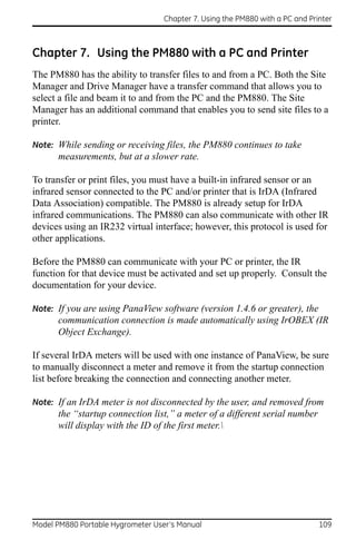
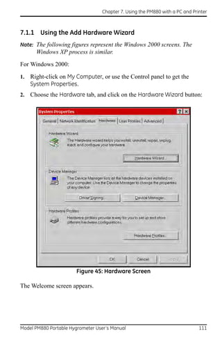
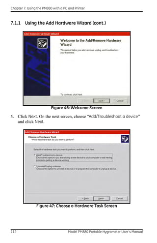
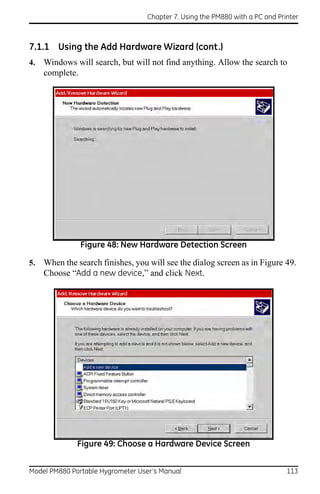
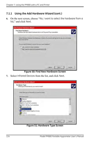
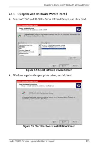
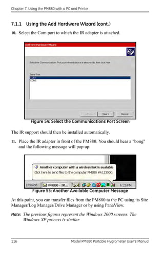
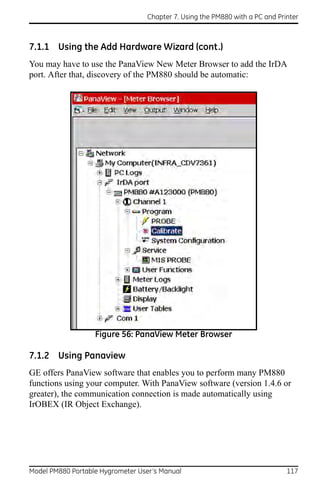
![Chapter 7. Using the PM880 with a PC and Printer
Use these steps if you need to change the PM880 IR set up:
7.1.2a Accessing the Meter Menu
1. If the menu is not active, press [MENU].
2. Use the arrow key to scroll to Meter and press [ENTER].
3. Use the arrow key to scroll to Communication and press [ENTER]. The
Communications window appears similar to Figure 57.
Figure 57: Communications Window
7.1.2b Changing Communication Setup
1. The Communications window displays the various parameters for IR
setup. Use the arrow keys to scroll to the desired parameters and press
[ENTER] to select or open a text box.
WARNING! Do NOT change the Node ID unless instructed to by GE.
IMPORTANT: Baud rate, parity, stop bits and data bits are active only when
IR232 is selected for the communication interface. IR232
requires the following parameters: 9600, None, 1 and 8
respectively.
2. Press [F3] (OK) and then press [MENU]. The PM880 returns to taking
measurements.
118 Model PM880 Portable Hygrometer User’s Manual](https://image.slidesharecdn.com/910-247flr-1-110719060037-phpapp02/85/910-247-f-lr-1-132-320.jpg)
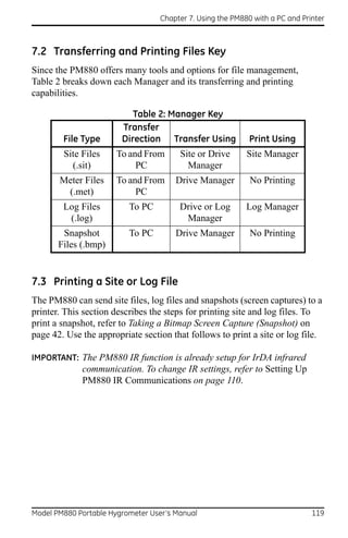
![Chapter 7. Using the PM880 with a PC and Printer
7.3.1 Printing a Site File
7.3.1a Accessing the Site Manager
1. If the menu in not active, press [MENU].
2. Use the arrow key to scroll to Site and press [ENTER].
3. Use the arrow key to scroll to Site Manager and press [ENTER].
7.3.1b Selecting a Site File
1. Use the arrow key to scroll to the desired site.
Note: The list of site files in the Site Manager can be listed chronologically
or alphabetically. Refer to Sorting Files in the Site/Drive/Log
Manager on page 108.
2. Press [MENU].
3. Use the arrow key to scroll to Site and press [ENTER].
4. Make sure the IR beam on the PM880 has clear access to the IR sensor
on the printer.
5. Use the arrow key to scroll to Print and press [ENTER].
The PM880 indicates that it is searching for a receiving printer. If it spots
more than one compatible infrared device within its range, it asks you to
select the desired device.
6. Once the PM880 finds the printer, it asks you to confirm, press [F3]
(Yes) and then press [MENU]. The PM880 returns to the Site Manager.
Next, do one of the following:
• If desired, repeat steps 1 through 6 in the previous section to print
another site file.
• To exit and return to taking measurements, press [F3] (Exit) and then
press [MENU].
120 Model PM880 Portable Hygrometer User’s Manual](https://image.slidesharecdn.com/910-247flr-1-110719060037-phpapp02/85/910-247-f-lr-1-134-320.jpg)
![Chapter 7. Using the PM880 with a PC and Printer
7.3.2 Printing a Log File
7.3.2a Accessing the Log Manager
1. If the menu is not active, press [MENU].
2. Use the arrow key to scroll to Logging and press [ENTER].
3. Use the arrow key to scroll to Log Manager and press [ENTER].
7.3.2b Selecting a Log File
1. Use the arrow key to scroll to the desired log. Logs are associated with
the site file in use at the time the log is created or run. If you do not see
the desired log in the list, refer to Viewing All Logs on page 85 to
display all the existing logs.
Note: The list of site files in the Log Manager can be listed chronologically
or alphabetically. Refer to Sorting Files in the Site/Drive/Log
Manager on page 108.
2. Press [MENU].
3. Use the arrow key to scroll to File and press [ENTER].
4. Use the arrow key to scroll to Print and press [ENTER].
Model PM880 Portable Hygrometer User’s Manual 121](https://image.slidesharecdn.com/910-247flr-1-110719060037-phpapp02/85/910-247-f-lr-1-135-320.jpg)
![Chapter 7. Using the PM880 with a PC and Printer
7.3 Printing a Site or Log File (cont.)
7.3.0a Entering a Time Window for Printing
1. The PM880 displays the start and end time of the log (see Figure 58).
Use the arrow and [ENTER] keys to change the start date and/or time to
indicate what portion of the log you want to print. Do not edit the time
to print the entire log.
-52.0
Enter Time
Start Date Start Time
2003/03/01 13:23:41 PM
End Date End Time
2003/03/01 13:53:41 PM
Figure 58: Enter Time Window
2. Make sure the IR beam on the PM880 has clear access to the IR sensor
on the printer and press [F3] (OK).
The PM880 indicates that it is searching for a receiving printer and then
sends the file. If it spots more than one compatible infrared device within its
range, it asks you to select the desired device.
Note: If the PM880 cannot detect an infrared device, a window appears
indicating this problem. Reposition the PM880 and press [F3],
Yes.Consult the factory if the PM880 is unable to make contact with
your PC.
Next, do one of the following:
• If desired, repeat the steps beginning in Selecting a Log File on the
previous page to print another log file.
• To exit and return to taking measurements, press [F3] (Exit) and then
press [MENU].
122 Model PM880 Portable Hygrometer User’s Manual](https://image.slidesharecdn.com/910-247flr-1-110719060037-phpapp02/85/910-247-f-lr-1-136-320.jpg)
![Chapter 7. Using the PM880 with a PC and Printer
7.4 Printing Reports
When used with an IR-compatible printer, the PM880 can print out a variety
of data (current site, logs, drive contents, and user functions, tables and
settings) using the Reports command. Use the steps below to print the
desired report:
IMPORTANT: The PM880 IR function is already setup for IrDA infrared
communication. To change IR settings, refer to Setting Up
PM880 IR Communications on page 110.
1. If the menu is not active, press [MENU].
2. Use the arrow keys to scroll to Service and press [ENTER].
3. Use the arrow keys to scroll to Reports and press [ENTER]. A screen
similar to Figure 59 appears.
Figure 59: Reports Window
4. Use the arrow keys to select the desired report.
5. Make sure the IR beam on the PM880 has clear access to the IR sensor
on the printer.
6. Press [F2] (Print) to print out the desired reports.
Model PM880 Portable Hygrometer User’s Manual 123](https://image.slidesharecdn.com/910-247flr-1-110719060037-phpapp02/85/910-247-f-lr-1-137-320.jpg)
![Chapter 7. Using the PM880 with a PC and Printer
7.4 Printing Reports (cont.)
Next, do one of the following:
• If desired, repeat steps 4 through 6 to print another report.
• To exit and return to taking measurements, press [F3] (Exit) and then
press [MENU].
7.5 Transferring a File To a PC
You can use the Site Manager, Drive Manager or the Log Manager to
transfer files to your PC. The Site Manager enables you to transfer site files
only; the Drive Manager enables you to transfer any file in the PM880; and,
the Log Manager enables you to transfer log files only.
Use the steps below to transfer files to your PC:
7.5.0a Preparing for File Transfer
1. The PM880 IR function is already setup for IrDA infrared
communication. To change IR settings, refer to Setting Up PM880 IR
Communications on page 110.
2. If you are using Windows NT 4.0, open the QuickBeam® software.
Proceed to the next section.
7.5.0b Accessing the Site, Drive or Log Manager
1. If the menu is not active, press [MENU].
2. To transfer:
• site, meter, log or snapshot files, press Site and press [ENTER].
• log files only, press Logging and press [ENTER].
3. Use the arrow key to scroll to:
• Site Manager and press [ENTER] - to transfer site files only.
• Drive Manager and press [ENTER] - to transfer all types of files.
• Log Manager and press [ENTER] - to transfer log files only.
124 Model PM880 Portable Hygrometer User’s Manual](https://image.slidesharecdn.com/910-247flr-1-110719060037-phpapp02/85/910-247-f-lr-1-138-320.jpg)
![Chapter 7. Using the PM880 with a PC and Printer
7.5.0c Selecting a File
1. Use the arrow key to scroll to the desired file. Logs are associated with
the site file in use at the time the log is created or run. If you do not see
the desired log in the list, refer to Viewing All Logs on page 85 to
display all the existing logs.
IMPORTANT: The list of site files in the Site/Drive/Log Manager can be
listed chronologically or alphabetically. Refer to Sorting Files
in the Site/Drive/Log Manager on page 108.
2. Press [MENU].
3. Use the arrow key to scroll to:
• For Site Manager - Site and press [ENTER].
• For Drive or Log Manager - File and press [ENTER].
4. Make sure the IR beam on the PM880 has clear access to the IR sensor
on the PC.
5. Use the arrow key to scroll to Transfer and press [ENTER].
6. The PM880 establishes communications with your PC and uploads the
selected file. Respond to any screen prompts from the PC.
When the upload is complete, the meter returns to the Site/Drive/Log
Manager.
IMPORTANT: If the PM880 cannot detect an infrared device, a window
appears indicating this problem. Reposition the PM880 and
press [F3] Yes. Consult the factory if the PM880 is unable to
make contact with your PC.
Model PM880 Portable Hygrometer User’s Manual 125](https://image.slidesharecdn.com/910-247flr-1-110719060037-phpapp02/85/910-247-f-lr-1-139-320.jpg)
![Chapter 7. Using the PM880 with a PC and Printer
7.5 Transferring a File To a PC (cont.)
7.5.0a Locating and Viewing the Transferred File
Your PC stores the transferred file in a default location. The location
depends on the PC’s operating system:
• Windows NT 4.0 - the transferred file is in the QuickBeam Inbox
folder.
• Windows 95/98/2000 - the transferred file appears in the default
folder. The default folder is set in the Windows Control Panel using
the Wireless Link/Infrared icon
.
Next, do one of the following:
• Use any text editor to open the file on your PC.
• If desired, repeat steps 1 through 6 (Selecting a File on the previous
page) to transfer another file.
• To exit and return to taking measurements, press [F3] (Exit) and then
press [MENU].
126 Model PM880 Portable Hygrometer User’s Manual](https://image.slidesharecdn.com/910-247flr-1-110719060037-phpapp02/85/910-247-f-lr-1-140-320.jpg)
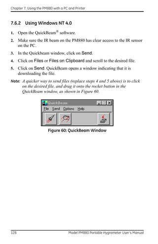
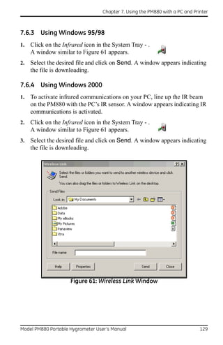
![Chapter 7. Using the PM880 with a PC and Printer
[no content intended for this page]
130 Model PM880 Portable Hygrometer User’s Manual](https://image.slidesharecdn.com/910-247flr-1-110719060037-phpapp02/85/910-247-f-lr-1-144-320.jpg)
![Chapter 8. Maintenance and Troubleshooting
8.1 Checking the PM880 Memory Status
The PM880 stores all types of files in its memory. Each type of Manager
enables you to monitor the size of a file and the remaining amount of
memory. Use the following steps to check the memory status:
8.1.0a Accessing the Site, Drive or Log Manager
1. If the menu is not active, press [MENU].
2. To check:
• site, meter, log or snapshot files, press Site and press [ENTER].
• log files only, press Logging and press [ENTER].
3. Use the arrow key to scroll to:
• Site Manager and press [ENTER] - to check site files only.
• Drive Manager and press [ENTER] - to check all types of files.
• Log Manager and press [ENTER] - to check log files only.
8.1.0b Selecting a Log File
1. Use the arrow key to scroll to the desired files. If you do not see the
desired log in the list, refer to Viewing All Logs on page 85 to display all
the existing logs.
Note: The list of files in each Manager can be listed chronologically or
alphabetically. Refer to Sorting Files in the Site/Drive/Log Manager
on page 108.
2. Check the lower right-hand corner of the window. You should see the
current date and time, the size of the selected file and the remaining
amount of memory.
Next, do one of the following:
• To check the size of another file, use the arrow keys to scroll to the
desired file.
• To exit and return to taking measurements, press [F3] (Exit) and then
press [MENU].
132 Model PM880 Portable Hygrometer User’s Manual](https://image.slidesharecdn.com/910-247flr-1-110719060037-phpapp02/85/910-247-f-lr-1-146-320.jpg)
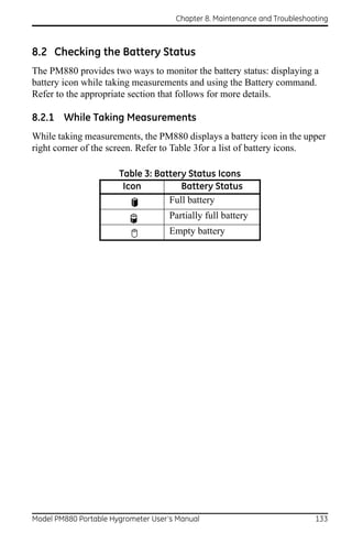
![Chapter 8. Maintenance and Troubleshooting
8.2.2 Using the Battery Command
The Battery command enables you to monitor the battery status more
closely. Use the following steps to check the battery status:
1. If the menu is not active, press [MENU].
2. Use the arrow key to scroll to Meter and press [ENTER].
3. Use the arrow key to scroll to Battery and press [ENTER]. A screen
similar to Figure 62 appears.
4. Press [F3] (Exit) to return to taking measurements.
Figure 62: Battery Charger Window
134 Model PM880 Portable Hygrometer User’s Manual](https://image.slidesharecdn.com/910-247flr-1-110719060037-phpapp02/85/910-247-f-lr-1-148-320.jpg)
![Chapter 8. Maintenance and Troubleshooting
8.3 Testing the Screen
1. If the menu is not active, press [MENU].
2. Use the arrow keys to scroll to Service and press [ENTER].
3. Use the arrow keys to scroll to Test and press [ENTER].
4. Use the arrow keys to scroll to Test Screen and press [ENTER]. A
screen with a checkerboard pattern appears as shown in Figure 63.
Figure 63: Functioning Test Screen
5. Press any key. The screen should redraw with the same checkerboard
pattern. Make sure the screen redraws properly.
6. Keep pressing keys to change the screen. The PM880 will sequence
through a number of dark and light screens before returning to taking
measurements. Make sure the screen keeps redrawing properly. If it
does not, please consult the factory.
Model PM880 Portable Hygrometer User’s Manual 135](https://image.slidesharecdn.com/910-247flr-1-110719060037-phpapp02/85/910-247-f-lr-1-149-320.jpg)
![Chapter 8. Maintenance and Troubleshooting
8.4 Testing the Keypad
1. If the menu is not active, press [MENU].
2. Use the arrow keys to scroll to Service and press [ENTER].
3. Use the arrow keys to scroll to Test and press [ENTER].
4. Use the arrow keys to scroll to Test Keys and press [ENTER]. The
screen appears similar to Figure 64.
Figure 64: Test Keys Window
5. Press any key on the keypad. The corresponding box on the screen
should darken.
Note: If the box does not darken or if the key does not appear on the screen,
contact the factory.
6. Press [F3] and then [MENU] to return to taking measurements. If any
key does not appear on the screen, contact the factory.
136 Model PM880 Portable Hygrometer User’s Manual](https://image.slidesharecdn.com/910-247flr-1-110719060037-phpapp02/85/910-247-f-lr-1-150-320.jpg)
![Chapter 8. Maintenance and Troubleshooting
8.5 Testing the Watchdog Timer Circuit
The PM880 includes a watchdog timer circuit. If a software error causes the
meter to stop responding, this circuit automatically resets the meter.
1. If the menu is not active, press [MENU].
2. Use the arrow keys to scroll to Service and press [ENTER].
3. Use the arrow keys to scroll to Test and press [ENTER].
4. Use the arrow keys to scroll to Watchdog Test and press [ENTER]. The
screen appears similar to Figure 65.
Figure 65: Watchdog Test Screen
5. Press [F3] (Yes) to start the test. The PM880 screen becomes blank for a
few seconds and then begins the boot sequence. If it does not follow this
sequence, consult the factory.
Model PM880 Portable Hygrometer User’s Manual 137](https://image.slidesharecdn.com/910-247flr-1-110719060037-phpapp02/85/910-247-f-lr-1-151-320.jpg)
![Chapter 8. Maintenance and Troubleshooting
8.6 Resetting to Factory Default Settings
The Factory Defaults command enables you to return the meter to its
preprogrammed default settings. The PM880 replaces the default site file
and the global meter settings with the factory default settings. To reset the
meter:
1. Transfer or print all sites and logs. Refer to Chapter 7, Using the PM880
with a PC and Printer.
WARNING! ALL SETTINGS IN THE DEFAULT SITE WILL BE RESET.
BE SURE TO TRANSFER OR PRINT ALL SITES AND LOGS
BEFORE RESETTING!
2. If the menu is not active, press [MENU].
3. Use the arrow keys to scroll to Service and press [ENTER].
4. Use the arrow keys to scroll to Factory Defaults and press [ENTER].
The screen appears similar to Figure 66.
Figure 66: Factory Defaults Window
138 Model PM880 Portable Hygrometer User’s Manual](https://image.slidesharecdn.com/910-247flr-1-110719060037-phpapp02/85/910-247-f-lr-1-152-320.jpg)
![Chapter 8. Maintenance and Troubleshooting
8.6 Resetting to Factory Default Settings (cont.)
5. Press [F3] (OK) to restore the factory default settings.
6. The program asks for confirmation: “Are you SURE?” Press [F3] (Yes).
The PM880 replaces the default site file and the global meter settings with
the factory default settings. When the meter returns to taking measurements,
it displays data using the default site.
8.7 Viewing or Changing Security Settings
To guard against accidental or intentional tampering, the PM880 includes a
password-based security system. The system has three security levels.
Individual passcodes protect the three security levels; they consist of one to
eight digits. The three levels are as follows:
• User Level - allows access to the display and non-critical meter
settings (such as resetting the clock).
• Operator Level - allows access to most of the meter settings used to
set up the meter such as probe selection and calibration data. This
level also allows you to delete files such as old logs and unneeded
site files.
• Service Level - provides access to all meter settings, and is available
to GE representatives and authorized service agents only.
The backup battery maintains the file system, so that if the battery fails or
the drive is erased, the passcodes will revert to the default values. For both
the User and Operator level, the default code is 2719.
Use the sections that follow to set up security levels and enter new
passcodes.
• Setting the Security Passcodes - see the next page
• Setting Remote Access Security - page 141
Model PM880 Portable Hygrometer User’s Manual 139](https://image.slidesharecdn.com/910-247flr-1-110719060037-phpapp02/85/910-247-f-lr-1-153-320.jpg)
![Chapter 8. Maintenance and Troubleshooting
8.7.1 Setting the Security Passcodes
Use the following steps to enter new security passcodes:
1. If the menu is not active, press [MENU].
2. Use the arrow keys to scroll to Service and press [ENTER].
3. Use the arrow keys to scroll to Security Settings and press [ENTER].
4. Use the arrow keys to move to the Passwords tab and press [ENTER].
The screen appears similar to Figure 67.
Figure 67: Passcode Entry Window
5. Use the arrow keys to scroll to the desired passcode text box and press
[ENTER].
6. Use the numeric keys to enter the new passcode (1 to 8 digits) and press
[ENTER].
IMPORTANT: Be sure to keep a record of the new passcode.
Next, do one of the following:
• To change remote access settings, refer step 4 in Setting Remote
Access Security on page 141.
• To exit and return to taking measurements, press [F3] (OK) and then
[MENU].
140 Model PM880 Portable Hygrometer User’s Manual](https://image.slidesharecdn.com/910-247flr-1-110719060037-phpapp02/85/910-247-f-lr-1-154-320.jpg)
![Chapter 8. Maintenance and Troubleshooting
8.7.2 Setting Remote Access Security
The PM880 enables you to set remote access security for each security
level. Remote access consists of allowing the PM880 to communicate with
PanaLink (GE software), receive files from a PC using IrDA, and transmit
files to a PC using IrDA. To set remote access:
Note: The remote access security settings are available only to users with
Operator or Service level passcodes.
1. Press [MENU].
2. Use the arrow keys to scroll to Service and press [ENTER].
3. Use the arrow keys to scroll to Security Settings and press [ENTER].
4. Use the arrow keys to move to the Level tab and press [ENTER]. The
screen appears similar to Figure 68.
Figure 68: Security Level Window
Model PM880 Portable Hygrometer User’s Manual 141](https://image.slidesharecdn.com/910-247flr-1-110719060037-phpapp02/85/910-247-f-lr-1-155-320.jpg)
![Chapter 8. Maintenance and Troubleshooting
8.7.2 Setting Remote Access Security (cont.)
5. Use the arrow keys to move to Security Level and press [ENTER] to
open the drop-down menu.
6. Scroll to the desired level and press [ENTER].
7. The PM880 may ask you to enter a passcode depending on the level you
choose. Enter the passcode and press [ENTER].
Note: You can change the remote access security settings for the Service
Level; however, you will need to enter the passcode for that level.
Contact the factory.
8. Use the arrow keys to scroll to the desired options. Press [ENTER].
When an “X” appears in the box, access is granted.
Next, do one of the following:
• To change security passcodes, refer to step 4 in Setting the Security
Passcodes on page 140.
• To exit and return to taking measurements, press [F3] (OK) and then
[MENU].
142 Model PM880 Portable Hygrometer User’s Manual](https://image.slidesharecdn.com/910-247flr-1-110719060037-phpapp02/85/910-247-f-lr-1-156-320.jpg)
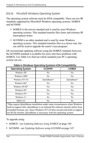
![Chapter 8. Maintenance and Troubleshooting
8.8.2 Updating Software Using IrOBEX
Use the sections below to upgrade the PM880 software using IrOBEX.
8.8.2a Setting Up PM880
1. Press [MENU].
2. Use the arrow keys to scroll to Service and press [ENTER].
3. Use the arrow keys to scroll to Flash Update and press [ENTER]. The
screen appears similar to Figure 69.
Figure 69: Flash Update Window
4. Press [F3] (OK) to confirm that you wish to erase the program.
5. The meter asks for confirmation. Press [F3] (OK) to continue with the
update.
6. After the PM880 reboots, the meter will ask you a series of questions.
Use the appropriate function key to respond, then refer to the next
section.
Model PM880 Portable Hygrometer User’s Manual 145](https://image.slidesharecdn.com/910-247flr-1-110719060037-phpapp02/85/910-247-f-lr-1-159-320.jpg)
![Chapter 8. Maintenance and Troubleshooting
8.8.3 Updating Software Using IrCOMM
Use the sections below to upgrade the PM880 software using IrCOMM.
8.8.3a Setting up the PC
Note: The use of Hyperterminal is shown here as an example. If you are
using a different communications software, see its manual for
detailed instructions.
1. From the Start Menu, click Programs/Accessories/Hyperterminal to
open the Hyperterminal window.
2. If the call is not connected, click on Connect from the Call menu in
Hyperterminal.
3. From the File menu, click Properties. Be sure the New Connection
Properties window is set to your virtual infrared port.
Note: You can determine which virtual port your infrared is using by
opening Infrared Monitor in the Control Panel and clicking on the
Options tab. It displays the message, “Providing Application Support
on:” and then lists the virtual infrared port.
8.8.3b Setting Up PM880
1. If the menu is not active, press [MENU].
2. Use the arrow keys to scroll to Service and press [ENTER].
3. Use the arrow keys to scroll to Flash Update and press [ENTER].
Screen appears similar to Figure 70 on page 148.
4. Press [F3] (OK) to confirm that you wish to erase the program.
5. The meter asks for confirmation. Press [F3] (OK) to continue with the
update.
6. After the PM880 reboots, the meter will ask you a series of questions.
Use the appropriate function key to respond, then refer to the next
section.
Model PM880 Portable Hygrometer User’s Manual 147](https://image.slidesharecdn.com/910-247flr-1-110719060037-phpapp02/85/910-247-f-lr-1-161-320.jpg)
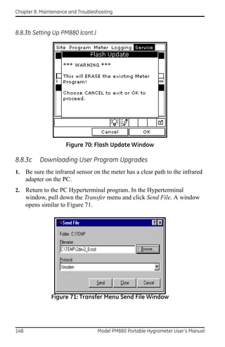
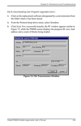
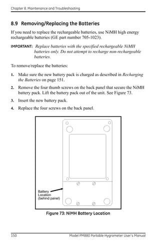


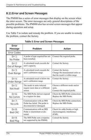
![Chapter 8. Maintenance and Troubleshooting
Table 5: Error and Screen Messages (cont.)
Error
Message Problem Action
Err 11: No reference values were Enter reference values.
No Reference entered for a moisture or
pressure probe.
Err 12: No No calibration curve was entered Enter calibration curve.
Calibration for a moisture or pressure probe.
Err 15: An internal calibration Contact the factory.
Cal Error reference has failed during
AutoCal, or a probe failure is
interfering with AutoCal.
Err 25: The MIS Probe has not The PM880 will try to send data;
No Data responded, or a calculation is not wait for next update.
yet complete.
MIS Probe
Calibration This screen appears when new Press [F3] (OK) to overwrite
data will be calibration data is manually existing data. Pressing OK
written to the entered in the Calibrate menu. overwrites the calibration data
stored in the MIS probe electronics
attached MIS module.
probe. Press [F2] (Cancel) to
discontinue.
These setup This screen appears when new Press [F3] (OK) to
values will be setup data is manually entered in overwrite existing data. Pressing
written to the the Service, MIS Probe menu. OK overwrites the setup data (e.g.
reference values) stored in the MIS
attached MIS probe electronics module.
probe.
Press [F2] (Cancel) to
discontinue.
Model PM880 Portable Hygrometer User’s Manual 155](https://image.slidesharecdn.com/910-247flr-1-110719060037-phpapp02/85/910-247-f-lr-1-169-320.jpg)
![Chapter 8. Maintenance and Troubleshooting
Table 5: Error and Screen Messages (cont.)
Error
Message Problem Action
MIS Probe (cont.)
No link to the This screen appears when trying Press [F3] (OK) to cancel all
MIS probe. to write to a disconnected MIS writes. The PM880 will read from
probe. the next connected MIS probe.
During the “No Link”condition,
the Hygro and Pressure tabs in the
Calibrate menu are disabled. These
calibration values are erased until a
new probe is connected.
A MIS probe This screen appears after a probe Press [F3] (OK) to cancel all
change has change. writes. The PM880 will read data
been from the next connected MIS
probe.
detected.
MISC
Probe due for This screen appears at the Send probe back to factory for
calibraton. user-programmed interval in the recalibration. If you are recalibrat-
Probe ID tab in the Calibrate ing a MIS probe, make sure you
menu. send the electronics module back
with the probe.
Press [ENTER] to temporarily
clear the reminder.
To turn off the reminder, use the
Program, Calibrate, Probe ID
menus. Turn Cal Reminder to
None.
If you see this This screen appears if the Press [F3] (OK) to continue.
message, the watchdog timer circuit fails the Contact the factory.
watchdog test watchdog test (Service, Test,
has FAILED. Watchdog Test menu).
Please consult
the factory for
instructions.
156 Model PM880 Portable Hygrometer User’s Manual](https://image.slidesharecdn.com/910-247flr-1-110719060037-phpapp02/85/910-247-f-lr-1-170-320.jpg)
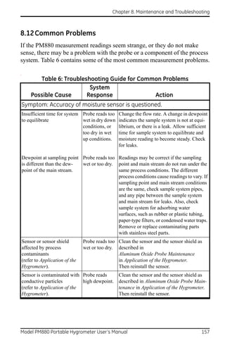
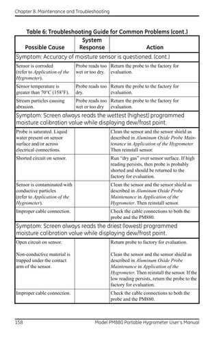
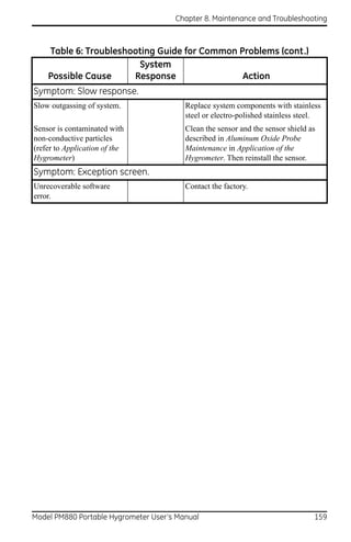
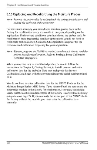
![Chapter 8. Maintenance and Troubleshooting
8.14 Recalibrating the Pressure Sensors
Since the pressure sensor on a TF Probe or on Moisture Image Series (MIS)
Probes is a strain gage type, the pressure calibration is linear and is
calibrated at 2 data points. Each point consists of a voltage or FP value and
a corresponding pressure value in psig. Check or change the two calibration
data points using the steps below.
1. Set one of the boxes on the screen to display pressure in mV (or FP) and
another box to display psig. Refer to Displaying Measurements on
page 15 to set up the screen.
2. Expose the pressure sensor to air and record the mV (or FP) and psig
readings. This reading is for the zero pressure.
3. Expose the pressure sensor to a known full scale pressure source and
record the mV (or FP) and psig readings. This reading is for the span
pressure.
4. Press [MENU].
5. Use the arrow key to scroll to Program and press [ENTER].
6. Use the arrow key to scroll to Calibration and press [ENTER].
7. Proceed to Entering Pressure Calibration Data on page 14 to complete
entering data.
Model PM880 Portable Hygrometer User’s Manual 161](https://image.slidesharecdn.com/910-247flr-1-110719060037-phpapp02/85/910-247-f-lr-1-175-320.jpg)
![Chapter 8. Maintenance and Troubleshooting
[no content intended for this page]
162 Model PM880 Portable Hygrometer User’s Manual](https://image.slidesharecdn.com/910-247flr-1-110719060037-phpapp02/85/910-247-f-lr-1-176-320.jpg)
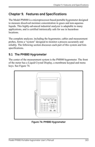
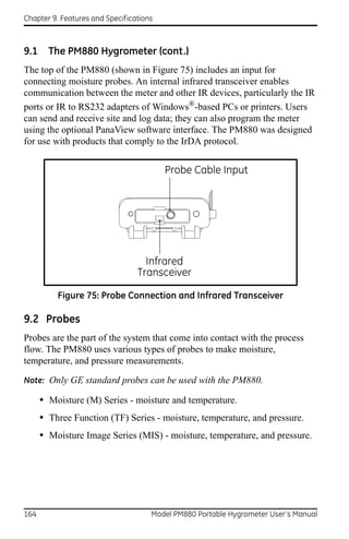
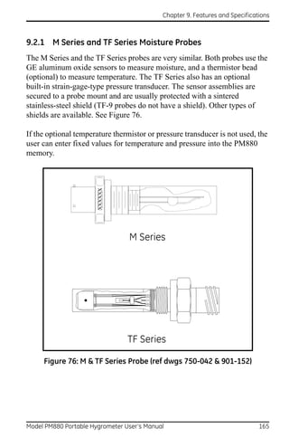
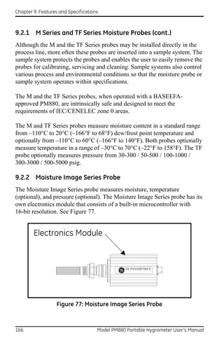
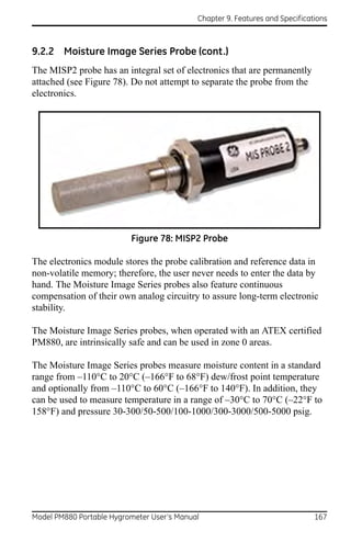
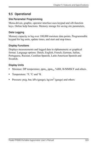


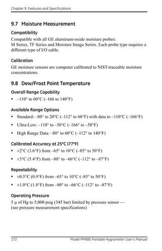
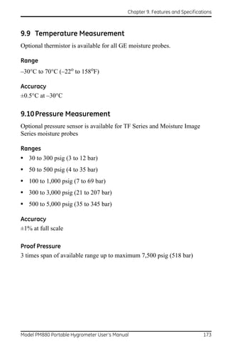
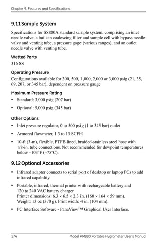

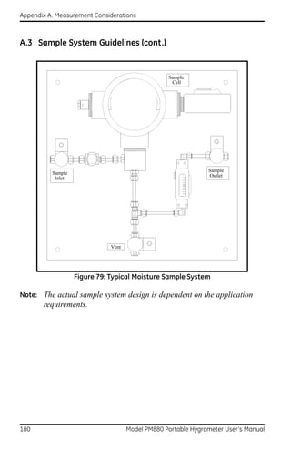

![Appendix B. Menu Maps
[no content intended for this page]
182 Model PM880 Portable Hygrometer User’s Manual](https://image.slidesharecdn.com/910-247flr-1-110719060037-phpapp02/85/910-247-f-lr-1-196-320.jpg)
![Appendix B. Menu Maps
M enu
S ite P ro g ra m M e te r L og g in g S e rvice
See See S ee See
F ig ure 8 1 F ig u re 8 2 F ig u re 8 3 F ig u re 8 4
M anager S a ve 1 V ie w 2 V ie w 3 V iew 4 V iew F ke ys About
F1 F2 F3 C le ar C le a r C le a r
F1 F2 F3
F ile S ite S ort
M en u Ite m
M e ssa g e P rin t T ra n sfe r Nam e D ate
D rive
M an a ge r
F ile S o rt
N ew O p en S a ve S a ve as R e fre sh Renam e D elete T ra n sfe r R efresh D e lete N am e D a te
N am e F ile Nam e N am e F ile
F ile
N o te s: P re ss [F 2 ] (C a n ce l) to ca n ce l th e e n trie s an d re tu rn to M e n u.
P re ss [F 3 ] (O K ) to co n firm th e e n trie s a n d re tu rn to M e n u .
Figure 80: Site Menu
Model PM880 Portable Hygrometer User’s Manual 183](https://image.slidesharecdn.com/910-247flr-1-110719060037-phpapp02/85/910-247-f-lr-1-197-320.jpg)
![Appendix B. Menu Maps
M enu
S ite P ro g ram M e te r L o gg ing S e rvice
S ee S ee S ee S ee
F ig ure 80 F ig ure 82 F ig u re 8 3 F ig u re 8 4
P ro be C a lib ra te S yste m U se r
F un ction s
A u to C a l In terval
K X PPMv
M2 M 2T TF M IS P None H yg ro P re ssure S a tu ra tion P ro b e ID R es p o nse
M H (F H ) Z e ro FP Tem p C S e ria l N u m be r U se r1 U se r2 U se r3 U se r4
D e w P o int Z e ro kP a Cs C a lib ra te d O n
H yg ro C o n stant Span FP C a l R e m inde r
T e m pe ra ture C on stant S p a n kP a U se r1 U se r2 U se r3 U se r4
P re ssu re C o nsta nt
N orm CER DEF
La b e l
T S ystem
U n its S ym bol
T S e n so r
D e cim a l P lace s
0 1 2 3 4
N o te s: P re ss [F 2 ] (C a n ce l) to c a n ce l th e e n trie s a nd return to M e nu.
P re ss [F 3 ] (O K ) to co n firm the e n trie s a n d return to M e nu.
E q u a tio n
Figure 81: Program Menu
Model PM880 Portable Hygrometer User’s Manual 184](https://image.slidesharecdn.com/910-247flr-1-110719060037-phpapp02/85/910-247-f-lr-1-198-320.jpg)
![Appendix B. Menu Maps
N otes : P re ss [F 2 ] (C an ce l) to ca nc el the e ntries an d return to M enu. M en u
P re ss [F 3 ] (O K ) to co n firm the en trie s an d re turn to M enu .
S ite P rog ram M eter L og ging S ervice
S ee See S ee S ee
F igure 80 F igure 8 1 F igure 83 F igu re 84
U nits B a ttery D a te/T im e Lo ca le C o ntra st B ackligh t L angu age C om m un ications U ser T a bles S nap shot
D a te B a cklight
O ff T ab le
T im e
E nglish M e tric D arker L igh ter E ng lish O th er 1 2 3 4 5 6
S ite M essage D a te S e pa rator ID O ff P rinter F ile
C om m In te rface
# D ata P oints
– , / M ax P oints
IrD A IR 232
E d it T ab le s
T im e S e pa rator B au d R ate
. : 3 00 60 0 12 00 240 0 4800 9 600 1 9.2K 3 8.4K 5 7.6K 11 5.2K
D e cim a l P a rity
. , N on e M ark S pace E ven O dd
D a te F o rm at S to p B its
Y Y Y Y /M M M M /D D D D /M M 1 2
T im e F o rm at D ata B its
1 2 H ou r 2 4 H our 7 8
Figure 82: Meter Menu
Model PM880 Portable Hygrometer User’s Manual 185](https://image.slidesharecdn.com/910-247flr-1-110719060037-phpapp02/85/910-247-f-lr-1-199-320.jpg)
![Appendix B. Menu Maps
M enu
S ite P ro g ra m M ete r L o gg in g S e rvice
See See See S ee
F ig ure 8 0 F igu re 8 1 F ig ure 8 2 F igu re 8 4
L o g M a n a g er N ew L og
Nam e
F ile Lo g V ie w S o rt F orm a t
L in e ar C ircu la r
D eta ils G rap h S pre a d she e t Nam e D a te
T yp e
S ta rt P a u se End P a use A ll S ta rt A ll E n d A ll V ie w A ll S tan da rd E rro r
N am e S ta rt
End
Inte rval
M e a su re m e n t
N ew C lo n e L o g R e n am e D e le te D ele te A ll R e fre sh T ra n sfer
N am e Nam e
F o rm a t Nam e
L ine a r C ircu la r
T yp e N o tes: P re ss [F 2 ] (C an ce l) to ca n ce l the e n trie s a n d re turn to M e n u.
P re ss [F 3 ] (O K ) to co n firm th e en trie s a n d re turn to M e n u.
S ta n da rd E rror
S ta rt
End
In te rva l
M e asu re m en t
Figure 83: Logging Menu
Model PM880 Portable Hygrometer User’s Manual 186](https://image.slidesharecdn.com/910-247flr-1-110719060037-phpapp02/85/910-247-f-lr-1-200-320.jpg)
![Appendix B. Menu Maps
M enu
S ite P rogram M e ter Lo gging S ervice
S ee S ee S ee S ee
F ig ure 80 F igure 81 F ig ure 82 F igure 83
R e ports T est R eferences M IS P robe F acto ry F lash S ecurity F actory
(F actory D efaults U pda te S ettings C alibra tion
U se O nly) (F a ctory
U se O nly)
H ygro P ressure E n ter
T est T est W atchdog P a ssw ord
S creen K eys T est
H igh
Lo w Level P a ssw ord
D rive C ontents C urrent S ite G loba l S ettings U ser F unctions
U ser T ables U se r S e ttings M en u C om m ands A ll
N otes:
P ress [F 2] (C a nce l) to cancel the entries and return to M enu.
P ress [F 3] (O K ) to confirm the en trie s and retu rn to M e nu .
Figure 84: Service Menu
Model PM880 Portable Hygrometer User’s Manual 187](https://image.slidesharecdn.com/910-247flr-1-110719060037-phpapp02/85/910-247-f-lr-1-201-320.jpg)
![Appendix B. Menu Maps
[no content intended for this page]
Model PM880 Portable Hygrometer User’s Manual 188](https://image.slidesharecdn.com/910-247flr-1-110719060037-phpapp02/85/910-247-f-lr-1-202-320.jpg)
![Index
[no content intended for this page]
198 Model PM880 Portable Hygrometer User’s Manual](https://image.slidesharecdn.com/910-247flr-1-110719060037-phpapp02/85/910-247-f-lr-1-212-320.jpg)