Downloaded 17 times

![⁃picture⁃based prediction coding can improve the coding effi⁃
ciency significantly. Furthermore, the background picture can
also be used for object detection and tracking for intelligent
surveillance video coding.
This paper gives an overview of AVS2 video coding standard
and a performance comparison with others. The paper is orga⁃
nized as follows. Section 2 introduces the flexible coding struc⁃
ture in AVS2. Section 3 gives an overview of key tools adopted
in AVS2. The specially developed scene video coding is shown
in Section 4. Section 5 provides the performance comparison
between AVS2 and other state⁃of⁃the⁃art standards. Finally,
Sections 6 concludes the paper.
2 Flexible Coding Structure in AVS2
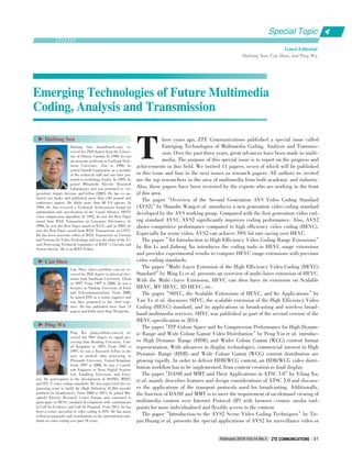
In AVS2, a flexible coding unit (CU), prediction unit (PU)
and transform unit (TU) based coding/prediction/transform
structure is used to represent and organize the encoded data
[1], [2]. First, pictures are split into largest coding units
(LCUs), which consist of 2N x 2N samples of luminance compo⁃
nent and associated chrominance samples with N = 8, 16 or
32. One LCU can be a single CU or can be split into four small⁃
er CUs with a quad⁃tree partition structure. A CU can be recur⁃
sively split until it reaches the smallest CU size (Fig. 2a).
Once the splitting of the CU hierarchical tree is finished, the
leaf node CUs can be further split into PUs. A PU is the basic
unit for intra⁃ and inter⁃prediction and allows different shapes
to encode irregular image patterns (Fig. 2b). The size of a PU
is limited to that of a CU with various square or rectangular
shapes. Specifically, both intra⁃ and inter⁃prediction partitions
can be symmetric or asymmetric. Intra ⁃ prediction partitions
vary in the set {2Nx2N, NxN, 2Nx0.5N, 0.5Nx2N}, and inter⁃
prediction partitions vary in the set {2Nx2N, 2NxN, Nx2N,
2NxnU, 2NxnD, nLx2N, nRx2N}, where U, D, L and R are the
abbreviations of Up, Down, Left and Right respectively. n is
equal to 0.25N. Besides CU and PU, TU is also defined to rep⁃
resent the basic unit for transform coding and quantization.
The size of a TU cannot exceed that of a CU, but it is indepen⁃
dent of the PU size.
3 Main Coding Tools in AVS2
AVS2 uses more efficient coding tools to make full use of
the textual information and spatial/temporal redundancies.
These tools can be classified into four categories: 1) prediction
coding, including intra prediction and inter prediction; 2) trans⁃
form; 3) entropy coding; and 4) in⁃loop filtering.
3.1 Intra Prediction
AVS2 still uses a block⁃partition⁃based directional predic⁃
tion to reduce the spatial redundancy in the picture [3]. Com⁃
pared with AVS1, more intra coding modes are designed to im⁃
prove the prediction accuracy. Besides the square PU parti⁃
tions, non⁃square partitions, called short distance intra predic⁃
tion (SDIP), are used by AVS2 for more efficient intra lumi⁃
nance prediction [4], where the nearest reconstructed bound⁃
ary pixels are used as the reference sample in intra prediction
(Fig. 2). For SDIP, a 2Nx2N CU is horizontally or vertically
partitioned into four PUs. SDIP is more adaptive to the image
content, especially in areas with complex textures. To reduce
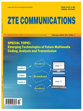
complexity, SDIP is disabled for a 64 x 64 CU. For each pre⁃
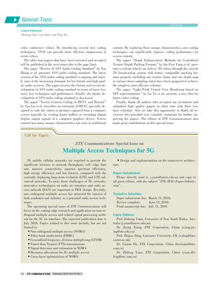
diction block in the partition modes, 33 prediction modes are
supported for luminance, including
30 angular modes [3], plane mode,
bilinear mode and DC mode. As in
Fig. 3, the prediction directions as⁃
sociated with the 30 angular modes
are distributed within the range of
[ ⁃ 157.5° , 60° ]. Each sample in a
PU is predicted by projecting its lo⁃
cation to the reference pixels in the
selected prediction direction. To im⁃
prove intra⁃prediction accuracy, the
sub ⁃ pixel precision reference sam⁃
ples are interpolated if the project⁃
ed reference samples locate on a
non⁃integer position. The non⁃inte⁃
ger position is bounded to 1/32 sam⁃
ple precision to avoid floating point
operation, and a 4⁃tap linear inter⁃
polation filter is used to obtain the
sub⁃pixel. During the coding of lu⁃
ma prediction mode, two most prob⁃
able modes (MPMs) are used for
(a)
Split flag=0
▲Figure 2. (a) Maximum possible recursive CU structure in AVS2 (LCU size= 64, maximum hierarchical
depth = 4), (b) Possible PU splitting for skip, intra and inter modes in AVS2.
CU: coding unit PU: prediction unit
(b)
CU0
0 1
2 3
Split flag=1
2N0
2N0
Split flag=0
CU1
0 1
2 3
Split flag=1
2N1
2N1
Split flag=0
CU2
0 1
2 3
Split flag=1
2N2
2N2
CU3
2N3
2N3
Last depth: no spliting flag
CU depth, d=0
N0=32
CU depth, d=1
N1=16
CU depth, d=2
N2=8
CU depth, d=3
N3=4
CU partition
2Nd×2Nd PU_skip/direct
2Nd×2Nd Nd×Nd
PU partition
2Nd×0.5Nd 0.5Nd×2Nd PU_Intra
2Nd×2Nd 2Nd×Nd Nd×2Nd Nd×Nd
PU_Inter
2Nd×nU 2Nd×nD nL×2Nd nR×2Nd
n=0.25Nd
d=0
d=1
d=2
d=3
Special Topic
Overview of the Second Generation AVS Video Coding Standard (AVS2)
Shanshe Wang, Falei Luo, and Siwei Ma
February 2016 Vol.14 No.1ZTE COMMUNICATIONSZTE COMMUNICATIONS04](https://image.slidesharecdn.com/p020160311277843128165-160314232837/85/Emerging-Technologies-of-Future-Multimedia-Coding-Analysis-and-Transmission-8-320.jpg)
![prediction. If the current prediction mode equals one of the
MPMs, two bins are transmitted into the bitstream; otherwise,
six bins are needed.
For the chrominance component, the PU is always square,
and 5 prediction modes are supported, including vertical pre⁃
diction, horizontal prediction, bilinear prediction, DC predic⁃
tion and the prediction mode derived from the corresponding
luminance prediction mode [5].
3.2 Inter Prediction
Compared to the spatial intra prediction, inter prediction fo⁃
cuses on exploiting the temporal correlation between the con⁃
secutive pictures to reduce the temporal redundancy. AVS2
still adopts the multi⁃reference prediction as in AVS1, includ⁃
ing both short term and long term reference pictures. However,
inter prediction mode has been improved much and a more
flexible reference picture management scheme is adopted.
3.2.1 Improved Inter⁃Prediction Mode
In AVS2, inter prediction mode has been improved much to
further improve the inter prediction accuracy. Firstly, a new in⁃
ter frame type, called F frame, is defined as a special P frame
[6] in addition to the traditional P and B frames. Secondly, new
inter coding modes are specially designed for F and B frame.
For F frame, besides the conventional single hypothesis pre⁃
diction mode as in a P frame, the significant improvement is
the use of multi⁃hypothesis techniques, including multi⁃direc⁃
tional skip/direct mode [7], temporal multi⁃hypothesis predic⁃
tion mode [8], and spatial directional multi⁃hypothesis (DMH)
prediction mode [9]. These modes improve the coding perfor⁃
mance of AVS2 by a large margin. Detailed descriptions are
shown as follows.
The multi⁃directional skip/direct mode in F frame is used to
merge current block to spatial or temporal neighboring block.
The difference between skip mode and direct mode is that skip
mode needs to encode residual information while direct mode
does not. However, the derivation of motion vector (MV) for the
two modes are the same. In AVS2, two derivation methods, one
of which is temporal and the other is spatial, are used. For tem⁃
poral derivation, one MV is achieved from the temporal collo⁃
cated block in the nearest or backward reference frame. The
other MV for weighted skip mode is obtained by scaling the
first derived MV in the second reference frame. The second ref⁃
erence is specified by the reference index transmitted in the
bitstream, indicating weighted skip mode. For spatial deriva⁃
tion, the needed motion vectors, one or two, are obtained from
neighboring prediction blocks. If only one MV is needed, two
derivations are provided. One is to search the neighboring
blocks (Fig. 4) in a pre⁃defined order: F, G, C, A, B, D. The
other is to determine the MV by searching the neighboring
blocks in a reverse order. If the derived MVs do not belong to
the same block, the two MVs are available. Otherwise, the sec⁃
ond MV should be re⁃derived from the neighboring blocks us⁃
ing dual forward prediction. If two MVs are needed, the deriva⁃
tion scheme is the same as before. The difference is that when
the two MVs belong to the same block, the second MV should
re ⁃ derived by combining one MV single forward prediction
searched by the defined order and one MV searched by re⁃
versed order.
DMH mode provides a derivation scheme to generate two
seed predictors based on the initial predictor obtained from mo⁃
tion estimation to improve the inter prediction accuracy. As in
Fig. 5, all the optional seed predictors are located on the line
crossing the initial predictor. Considering the coding complexi⁃
ty, the number of seed predictors is restricted to 8, mode 1 to
mode 8. The derivation of the two seed predictors is shown in
Table 1. For one seed predictor mode with index as i, MV off⁃
set, denoted as
dmhi , is firstly obtained according to the table.
Then the needed two seed predictors,
mv1 and
mv2 , are calc⁃
▲Figure 3. Illustration of directional prediction modes.
PU: prediction unit
▲Figure 4. Illustration of neighboring blocks A, B, C, D, F and G for
motion vector prediction.
12
24
32
31
Zone3
Zone2
Zone1
30
29
28
27
26
25
2322
2120
19
18
16
17
15
13
1410
11
9
8
7
5
3
4
DC: 0
Plane: 1
Bilinear: 2
D B G C
A
F
Current PU
Special Topic
February 2016 Vol.14 No.1 ZTE COMMUNICATIONSZTE COMMUNICATIONS 05
Overview of the Second Generation AVS Video Coding Standard (AVS2)
Shanshe Wang, Falei Luo, and Siwei Ma
0](https://image.slidesharecdn.com/p020160311277843128165-160314232837/85/Emerging-Technologies-of-Future-Multimedia-Coding-Analysis-and-Transmission-9-320.jpg)
![Direct mode in F frames and B frames. Temporal motion vector
prediction is used for temporal derivation of Skip/Direct mode
in all inter frames. Spatial ⁃ temporal combined motion vector
prediction is used for temporal derivation of Skip/Direct mode
in B frames. For other cases, median prediction is used. More⁃
over, in order to improve the MV prediction accuracy, the deri⁃
vation of MV is achieved by the reference distance based scal⁃
ing.
In AVS2, the motion vector is in quarter⁃pixel precision for
the luminance component, and the sub ⁃ pixel is interpolated
with an 8⁃tap DCT interpolation filter (DCT⁃IF) [10]. For the
chrominance component, the motion vector derived from lumi⁃
nance with 1/8 pixel precision and a 4⁃tap DCT⁃IF is used for
sub⁃pixel interpolation [11]. The filter coefficients for sub⁃pix⁃
el interpolation is defined in Table 3. After motion vector pre⁃
diction, the motion vector difference (MVD) is coded in the bit⁃
stream. However, redundancy may still exist in MVD, and to
further save coding bits of motion vectors, a progressive motion
vector resolution (PMVR) adaptation method is used in AVS2
[12]. In PMVR, MVP is first rounded to the nearest half sam⁃
ple position, and then the MVDis rounded to half⁃pixel preci⁃
sion if it exceeds a threshold. Furthermore, the resolution of
MVD is decreased to integer⁃pel precision if it exceeds another
threshold. In AVS2, only one threshold is used, which means
that if the distance between the MV and MVP is less than the
threshold, quarter⁃pixel based MVD is coded; otherwise,half⁃
pixel based MVD is coded(actually, the MVD is separated into
two parts and coded with different resolution. The part of MVD
within the window will be coded at 1/4 pixel resolution, and
the other part will be coded at half⁃pixel resolution).
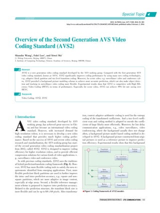
3.4 Transform
Unlike the transform in AVS1, a flexible TU partition struc⁃
ture is used to further compress the predicted residual in
AVS2. For CU with symmetric prediction unit partition, the TU
size can be 2Nx2N or NxN signaled by a transform split flag.
For CU with asymmetric prediction unit partition, the TU size
can be 2Nx2N, nx2N or 2Nxn. Thus, the maximum transform
size is 64x64, and the minimum is 4x4. For TU size from 4x4
to 32x32, an integer transform (IT) that closely approximates
the performance of the discrete cosine transform (DCT) is
used. For a square residual block, the forward transform matri⁃
ces from 4x4 to 32x32. Here,4x4 transform T4 and 8x8 trans⁃
form T8 are:
T4 =
é
ë
ê
êê
ê
ù
û
ú
úú
ú
32 32 32 32
42 17 -17 42
32 -32 -32 32
17 -42 42 -17
(3)
T8 =
é
ë
ê
ê
ê
ê
ê
êê
ê
ê
ê
ê
ê
ù
û
ú
ú
ú
ú
ú
úú
ú
ú
ú
ú
ú
32 32 32 32 32 32 32 32
44 38 25 9 -9 -25 -38 -44
42 17 -17 -42 -42 -17 17 42
38 -9 -44 -25 25 44 9 -38
32 -32 -32 32 32 -32 -32 32
25 -44 9 38 -38 -9 44 -25
17 -42 42 -17 -17 42 -42 17
9 -25 38 -44 44 -38 25 -9
(4)
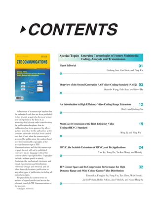
For a 64x64 transform, a logical transform (LOT) [13] is ap⁃
plied to the residual. A 5 ⁃ 3 tap integer wavelet transform is
first performed on a 64x64 block discarding the LH, HL and
HH⁃bands, and then a normal 32x32 IT is applied to the LL⁃
band. For all the PU partitions of a CU, 2Nx2N IT is used in
the first level, and a non⁃square transform [14] is used in the
second level (Fig. 7).
Furthermore, a secondary transform can be used to reduce
the correlation for luminance intra⁃prediction residual block.
The secondary transform matrix is related to the block size. If
the transform block size is greater than or equal to 8x8, a 4x4
secondary transform with matrix S4 is applied to the left corner
of the transform block as shown in Fig. 8. If the transform
block size is 4x4, an independent transform matrixD4 rather
▼Table 3. DCT⁃like interpolation filter for sub⁃pixel interpolation
Interpolation
Luma
Chroma
Position
1/4
2/4
3/4
1/8
2/8
3/8
4/8
5/8
6/8
7/8
Coefficients
{ ⁃1, 4, ⁃10, 58, 17, ⁃5, 1, 0}
{⁃1, 4, ⁃11, 40, 40, ⁃11, 4, ⁃1}
{0, 1, ⁃5, 17, 58, ⁃10, 4, ⁃1 }
{ ⁃4, 62, 6, 0}
{ ⁃6, 56, 15, ⁃1}
{ ⁃5, 47, 25, ⁃3}
{ ⁃4, 36, 36, ⁃4}
{ ⁃3, 25, 47, ⁃5}
{ ⁃1, 45, 56, ⁃6}
{ 0, 6, 62, ⁃4}
PU: prediction unit TU: transform unit
▲Figure 7. PU partition and two⁃level transform coding.
2N ×N
2N ×nU 2N ×nD
N ×2N
nL×2N nR×2N
2N ×2N
N ×N
PU
Level 0
Level 1
TU
Special Topic
February 2016 Vol.14 No.1 ZTE COMMUNICATIONSZTE COMMUNICATIONS 07
Overview of the Second Generation AVS Video Coding Standard (AVS2)
Shanshe Wang, Falei Luo, and Siwei Ma](https://image.slidesharecdn.com/p020160311277843128165-160314232837/85/Emerging-Technologies-of-Future-Multimedia-Coding-Analysis-and-Transmission-11-320.jpg)
![than T4 is used.
3.5 Entropy Coding
The entropy coding used in AVS2 is inherited form AVS1.
The arithmetic coding engine is designed according to a loga⁃
rithmic model. Thus, the probability estimation is specified to
be multiplication⁃free and only using shifts and addition and
no look⁃up tables are needed.
For the transformed coefficients coding, a two⁃level coding
scheme is applied to the transform coefficient blocks [15].
First, a coefficient block is partitioned into 4x4 coefficient
groups (CGs) (Fig. 9). Then zig ⁃ zag scanning and Context ⁃
Based Adaptive Binary Arithmetic Coding (CABAC) is per⁃
formed at both the CG level and coefficient level. At the CG
level for a TU, the CGs are scanned in zig⁃zag order, and the
CG position indicating the position of the last non⁃zero CG is
coded first, followed by a bin string in the reverse zig⁃zag scan
order of significant CG flags indicating whether the CG con⁃
tains non ⁃ zero coefficients. At the coefficient level, for each
non⁃zero CG, the coefficients are further scanned into the form
of (run, level) pair in zig⁃zag order. Level and run indicate the
magnitude of a non⁃zero coefficient and the number of zero co⁃
efficients between two non⁃zero coefficients, respectively. For
the last CG, the coefficient position, which denotes the position
of the last non⁃zero coefficient in scan order, is coded first. For
a non⁃last CG, a last run is coded which denotes number of ze⁃
ro coefficients after the last non⁃zero coefficient in zig⁃zag scan
order. Then the (level, run) pairs in a CG are coded in reverse
zig⁃zag scan order.
For the context modeling, AVS2 uses a mode ⁃ dependent
context ⁃ selection design for intra ⁃ prediction blocks [16]. In
this context design, 33 intra⁃prediction modes are classified in⁃
to three prediction mode sets: vertical, horizontal, and diago⁃
nal. Depending on the prediction mode set, each CG is divided
to two regions (Fig. 10). The intra⁃prediction modes and CG re⁃
gions are applied in the context modeling of syntax elements in⁃
cluding the last CG position, last coefficient position and run
value. In addition, AVS2 takes more consideration on data de⁃
pendence reduction in context design and explores more possi⁃
bility for bypass mode as well.
3.6 InLoop Filtering
Compared to AVS1, AVS2 has made great improvement
over in⁃loop filtering. Except for de⁃blocking filter, two more
filtering processes are added to AVS2, called sample adaptive
offset (SAO) filtering [17] and adaptive loop filter (ALF) [18],
to further improve the reconstructed picture quality. Thus in⁃
loop filtering in AVS2 includes the following three sequential
procedures: deblocking filtering, SAO and ALF.
The deblocking filter is designed to remove the blocking arti⁃
facts caused by block transform and quantization. In AVS2,
the basic unit for deblocking filter is an 8x8 block. For each
8x8 block, deblocking filter is used only if the boundary be⁃
longs to either of CU boundary, PU boundary or TU boundary.
Unlike AVS1, gradient is considered for boundary strength
(BS) calculation and then BS is classified into more levels
based on the calculated gradient. When the boundary is not
the edge of a block which can be CU, PU or TU, BS is set to
the lowest value to reduce the complexity.
After the deblocking filter, an SAO filter is applied to re⁃
duce the mean sample distortion of a region. The basic unit of
SAO is defined as four pixels top⁃left the LCU region, which is
more flexible for parallelization. An offset is added to the re⁃
constructed sample for each SAO filter unit to reduce ringing
artifacts and contouring artifacts. There are two kinds of offset
DCT: discrete cosine transform
◀Figure 8.
Illustration of secondary
transform in AVS2.
S4 =
é
ë
ê
êê
ê
ù
û
ú
úú
ú
123 -35 -8 -3
-32 -120 30 10
14 25 123 -22
8 13 19 126
, D4 =
é
ë
ê
êê
ê
ù
û
ú
úú
ú
34 58 72 81
77 69 -7 -75
79 -33 -75 58
55 -84 73 -28
(5)
▲Figure 9. Sub⁃block scan for transform blocks of size 8x8, 16x16
and 32x32 transform blocks; each sub⁃block represents a 4x4
coefficient group.
▲Figure 10. Sub⁃block region partitions of 4x4 coefficient group in an
intra prediction block.
DCT coefficients
4×4 2nd Transform
N ×N block
•
8×8 block 16×16 block 32×32 block
A
B
A B
A
B
Special Topic
Overview of the Second Generation AVS Video Coding Standard (AVS2)
Shanshe Wang, Falei Luo, and Siwei Ma
February 2016 Vol.14 No.1ZTE COMMUNICATIONSZTE COMMUNICATIONS08](https://image.slidesharecdn.com/p020160311277843128165-160314232837/85/Emerging-Technologies-of-Future-Multimedia-Coding-Analysis-and-Transmission-12-320.jpg)
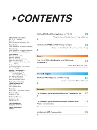
![called Edge Offset (EO) and Band Offset (BO) mode, respec⁃
tively.
Edge Offset mode first classifies the pixels in the filter unit
using four 1⁃D directional patterns as illustrated in Fig. 11. Ac⁃
cording to these patterns, four EO classes are specified, and on⁃
ly one EO class can be selected for each filter unit. For a given
EO class, samples of current filter unit are classified into one
of the five categories, which are based on the rules defined in
Table 4. For pixels in each category except category 0, an off⁃
set is derived by calculating the mean of the difference of re⁃
constructed pixel values and original pixel values. The offset
and the index of classification pattern are transmitted to a de⁃
coder.
Band offset mode classifies the pixels into 32 bands by
equally dividing the pixel range. Theoretically, one offset can
be derived for each band by calculating the mean of the differ⁃
ence of reconstructed pixel values and original pixel values.
However, more coding bits are necessary. Statistical results
show that the offsets of most pixel belong to a small domain.
Thus in AVS2, only four bands are selected in order to save
coding bits. Considering the fact that some sample values may
be quite different with the others, 2 start band positions are
transmitted to the decoder.
Besides EO and BO, merge technique is utilized in order to
save the bits consuming, where a merge flag is employed to in⁃
dicate whether the SAO parameters of the current LCU is exact
the same with its neighbors. When merge flag is enabled, all
the following SAO parameters are not signaled but inferred
from neighbors.
ALF is the last stage of in⁃loop filtering. Its nature is to mini⁃
mize the mean squared error between the original frame and
the reconstructed frame using Wiener⁃Hopf equations. There
are two stages in this process at encoder side. The first stage is
filter coefficient derivation. To achieve the filter coefficients,
reconstructed pixels of the luminance component are classified
into 16 categories, and one set of filter coefficients is trained
for each category using Wiener⁃Hopf equations. To reduce the
redundancy between these 16 sets of filter coefficients, the en⁃
coder will adaptively merge them based on the rate⁃distortion
performance. At its maximum, 16 different filter sets can be as⁃
signed for the luminance component and only one for each
chrominance component. The second stage is to filter each
sample with the corresponding derived filter coeffiencts using
a 7x7 cross and 3x3 square filter as shown in Fig. 12.
Finally,the filtered sample can be achieved as follows:
ptmp = ( )ptmp + 32 >> 6 (7)
p′( )x,y = Clip3( )0,( )1 << BitDepth - 1,ptmp (8)
where filterIdx indicates luma or chroma component, p(x,y)
is the reconstructed sample after SAO. p'(x,y) is the final recon⁃
structed sample after ALF. Hor[j]and Ver[j] stands for the filter
coefficients positions.
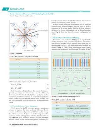
4 Scene Video Coding
In practical applications, many videos are captured in spe⁃
cific scenes, such as surveillance video and videos from class⁃
room, home, court, etc., which are characterized by temporally
stable background. The redundancy originating from the back⁃
ground could be further reduced. In AVS2, a background⁃pic⁃
ture⁃model⁃based coding method is proposed to achieve higher
compression performance [19] (Fig. 13). G⁃pictures and S⁃pic⁃
tures are defined to further exploit the temporal redundancy
and facilitate video event generation such as object segmenta⁃
tion and motion detection.
The G⁃picture is a special I⁃picture, which is stored in a sep⁃
arate background memory. It is encoded by intra mode only
and is not decoded for displaying. The reason is that it is just
for being referenced rather than for viewing. For the generation
of a G⁃picture,a method of segment⁃and⁃weight based running
▲Figure 11. Four 1⁃D directional EO patterns.
▼Table 4. The classification rules and pixel categories
Category
1
2
3
4
0
Condition
c < a && c < b
( c < a && c==b) || (c == a && c < b)
( c > a && c==b) || (c == a && c > b)
c > a && c > b
None of the above
Offset Range
⁃1 <= offset <= 6
0 <= offset <= 1
⁃1 <= offset <= 0
⁃6 <= offset <= 1
None
(6)
ptmp = C[ filterIdx][8]× p(x,y)+∑j = 0
7
C[ filterIdx][ j]×
(p(x - Hor[ j],y - Ver[ j])+ p(x + Hor[ j],y + Ver[ j]))
◀Figure 12.
Adaptive loop filter shape.
a b c
a
b
c
a
b
c
a
b
c
C5 C6 C7 C8 C5C6C7
C2 C3 C4
C1
C0
C4 C3 C2
C1
C0
Special Topic
February 2016 Vol.14 No.1 ZTE COMMUNICATIONSZTE COMMUNICATIONS 09
Overview of the Second Generation AVS Video Coding Standard (AVS2)
Shanshe Wang, Falei Luo, and Siwei Ma](https://image.slidesharecdn.com/p020160311277843128165-160314232837/85/Emerging-Technologies-of-Future-Multimedia-Coding-Analysis-and-Transmission-13-320.jpg)
![average (SWRA) [20] is used to generate the GB picture.
SWRA approximately generates the background by assigning
larger weights on the frequent values in the averaging process.
When encoding the G ⁃ picture, a smaller QP is selected to
make a high⁃quality G⁃picture. Then the G⁃picture can be well
referenced by the following pictures.
S⁃picture is a special P⁃picture that can only be predicted
from a reconstructed G⁃picture or virtual G⁃picture which does
not exist in the actual input sequence but is modeled from in⁃
put pictures and encoded into the stream to act as a reference
picture.Only intra, SKIP and P2N×2N modes with zero motion
vectors are available in S picture. In the AVS2, the S picture is
set as the random access point instead of intra⁃predicted pic⁃
ture. However, the S picture outperforms I picture when adopt⁃
ed as therandom access point since the inter prediction is ad⁃
opted in theS picture and the prediction performance is better.
With the S⁃picture, the performance of the random access can
be improved on a large scale.
Furthermore, according to the predication modes in AVS2
compression bitstream, the blocks of an AVS2 picture could be
classified as background blocks, foreground blocks or blocks
on the edge area. Obviously, this information is very helpful for
possible subsequent vision tasks, such as object detection and
tracking. Object ⁃ based coding has already been proposed in
MPEG ⁃ 4; however, object segmentation remains a challenge
that constrains the application of object based coding. There⁃
fore, AVS2 uses simple background modeling instead of accu⁃
rate object segmentation. The simple background modeling is
easier and provides a good tradeoff between coding efficiency
and complexity.
To provide convenience for applications like event detection
and searching, AVS2 adds some novel high⁃level syntax to de⁃
scribe the region of interest (ROI). In the region extension, the
region number, event ID, and coordinates for top left and bot⁃
tom right corners are included to show what number the ROI
is, what event happened and where it lies.
5 Performance Comparison
In this section, the performance comparisons among AVS2,
AVS1, and state ⁃ of ⁃ the ⁃ art High Efficiency Video Coding
(HEVC) international standard are provided. For comparison,
the reference software used in the experiments is HM16.6 for
HEVC, GDM 4.1 for AVS1 and RD12.0 for AVS2. HEVC and
AVS1 are used as a testing anchor. According to the applica⁃
tions, we tested the performance of AVS2 with three different
coding configurations:all⁃intra (AI), random access (RA), and
low delay (LD), similar to the HEVC common test conditions
and BD⁃Rate is used for bitrate saving evaluation. The UHD,
1080 p, 720 p, WVGA and WQVGA test sequences are the
common test sequences used in AVS2, including partial test se⁃
quences used in HEVC, such as Traffic (UHD), Kimono1
(1080 p), BasketballPass (WQVGA) and City (720 p). More⁃
over, surveillance sequences including 1200 p and 576 p are
tested to further compare the performance of AVS2 and HEVC
under their respective common test condition. All these se⁃
quences and the surveillance/videoconference sequences are
available on the AVS website.
Table 5 shows the rate distortion performance of AVS2 for
three test cases. For different test configurations, AVS2 shows
comparable performance as HEVC and outperforms AVS1 with
significant bits saving, up to 52.9% for RA. Table 6 shows the
rate distortion performance comparisons of AVS2 with HEVC
for surveillance sequences. AVS2 outperforms HEVC by
▲Figure 13. Background picture based scene coding in AVS2.
DCT: discrete cosine transform
IDCT: inverse discrete cosine transform
IQ: inverse quantization
MC: motion compensation
ME: motion estimation
▼Table 5. Bitrate saving of AVS2 performance comparison with
AVS1, HEVC for common test sequences
Sequences
UHD
1080 p
720 p
WVGA
WQVGA
Overall
AI configuration
AVS1 vs. AVS2
⁃31.2%
⁃33.1%
⁃34.0%
⁃30.4%
⁃26.6%
⁃31.2%
HEVC vs. AVS2
⁃2.21%
⁃0.67%
⁃2.06%
1.46%
2.78%
⁃0.06%
RA configuration
AVS1 vs. AVS2
⁃50.5%
⁃51.3%
⁃57.2%
⁃52.8%
⁃52.4%
⁃52.9%
HEVC vs. AVS2
⁃0.29%
⁃2.30%
⁃2.44%
0.05%
1.08%
⁃0.88%
LD configuration
AVS1 vs. AVS2
⁃57.6%
⁃44.3%
⁃56.3%
⁃50.5%
⁃49.4%
⁃51.0%
HEVC vs. AVS2
2.72%
0.68%
1.88%
0.91%
4.87%
2.11%
▼Table 6. Bitrate saving of AVS2 performance comparison with
HEVC for surveillance sequences
Sequences
1200 p
576 p
Overall
RA configuration
⁃35.7%
⁃41.3%
⁃39.1%
LD configuration
⁃38.5%
⁃26.5%
⁃31.3%
G⁃picture
initialization
Background
modeling
DCT&Q
Enctropy
coding
Bit
stream
Raw
video
Background
reference selection
S⁃picture decision
MC/Intra
Pred
ME
IQ and IDCT
Reconstruction
buffer
Loopfilter
Reference
memory
Background
memory
Decoder
Special Topic
Overview of the Second Generation AVS Video Coding Standard (AVS2)
Shanshe Wang, Falei Luo, and Siwei Ma
February 2016 Vol.14 No.1ZTE COMMUNICATIONSZTE COMMUNICATIONS10
HEVC: High Efficiency Video Coding AI: all⁃intra LD: low delay RA: random access
LD: low delay RA: random access](https://image.slidesharecdn.com/p020160311277843128165-160314232837/85/Emerging-Technologies-of-Future-Multimedia-Coding-Analysis-and-Transmission-14-320.jpg)
![39.1% and 31.3% under RA and LD test configuration, respec⁃
tively. The curves in Fig. 14 show the results on two surveil⁃
lance video sequences.
6 Conclusions
This paper gives an overview of the AVS2 standard. AVS2 is
an application oriented coding standard, and different coding
tools have been developed according to various application
characteristics and requirements. For high quality broadcast⁃
ing, flexible prediction and transform coding tools have been
incorporated. Especially for scene applications, AVS2 signifi⁃
cantly improves coding performance and bridges video com⁃
pression with machine vision by incorporating the background
picture modeling, thereby making video coding smarter and
more efficient. In a word, compared to the previous AVS1 cod⁃
ing standard, AVS2 achieves significant improvement both in
coding efficiency and flexibility.
(a) Mainroad
References
[1] S. Ma, S. Wang, and W. Gao,“Overview of IEEE 1857 video coding standard,”
in Proc. IEEE International Conference on Image Processing, Melbourne, Austra⁃
lia, Sept. 2013, pp.1500-1504. doi: 10.1109/MSP.2014.2371951.
[2] Q. Yu, S. Ma, Z. He, et al.,“Suggested video platform for AVS2,”42nd AVS
Meeting, Guilin, China, AVS_M2972, Sept. 2012.
[3] Y. Piao, S. Lee and C. Kim,“Modified intra mode coding and angle adjustment,”
48th AVS Meeting, Beijing, China, AVS_M3304, Apr. 2014.
[4] Q. Yu, X. Cao, W. Li, et al.,“Short distance intra prediction,”46th AVS Meet⁃
ing, Shenyang, China, AVS_M3171, Sept. 2013.
[5] Y. Piao, S. Lee, I.⁃K. Kim, and C. Kim,“Derived mode (DM) for chroma intra
prediction,”44th AVS Meeting, Luoyang, China, AVS_M3042, Mar. 2013.
[6] Y. Lin and L. Yu,“F frame CE: Multi forward hypothesis prediction,”48th AVS
Meeting, Beijing, China, AVS_M3326, Apr. 2014.
[7] Z. Shao and L. Yu,“Multi⁃hypothesis skip/direct mode in P frame,”47th AVS
Meeting, Shenzhen, China, AVS_M3256, Dec. 2013.
[8] Y. Ling, X. Zhu, L. Yu, et al.,“Multi⁃hypothesis mode for AVS2,”47th AVS
meeting, Shenzhen, China, AVS_M3271, Dec. 2013.
[9] I.⁃K. Kim, S. Lee, Y. Piao, and C. Kim,“Directional multi⁃hypothesis prediction
(DMH) for AVS2,”45th AVS Meeting, Taicang, China, AVS_M3094, Jun. 2013.
[10] H. Lv, R. Wang, Z. Wang, et al.,“Sequence level adaptive interpolation filter
for motion compensation,”47th AVS Meeting, Shenzhen, China, AVS_M3253,
Dec. 2013.
[11] Z. Wang, H. Lv, X. Li, et al.,“Interpolation improvement for chroma motion
compensation,”48th AVS Meeting, Beijing, China, AVS_M3348, Apr. 2014.
[12] J. Ma, S. Ma, J. An, K. Zhang, and S. Lei,“Progressive motion vector preci⁃
sion,”44th AVS Meeting, Luoyang, China, AVS_M3049, Mar. 2013.
[13] S. Lee, I.⁃K. Kim, Min⁃Su Cheon, N. Shlyakhov, and Y. Piao,“Proposal for
AVS2.0 Reference Software,”42nd AVS Meeting, Guilin, China, AVS_M2973,
Sept. 2012.
[14] W. Li, Y. Yuan, X. Cao, et al.,“Non⁃square quad⁃tree transform,”45th AVS
Meeting, Taicang, China, AVS_M3153, Jun. 2013.
[15] J. Wang, X. Wang, T. Ji, and D. He,“Two⁃level transform coefficient coding,”
43rd AVS Meeting, Beijing, China, AVS_M3035, Dec. 2012.
[16] X. Wang, J. Wang, T. Ji, and D. He,“Intra prediction mode based context de⁃
sign,”45th AVS Meeting, Taicang, China, AVS_M3103, Jun. 2013.
[17] J. Chen, S. Lee, C. Kim, et al.,“Sample adaptive offset for AVS2,”46th AVS
Meeting, Shenyang, China, AVS_M3197, Sept. 2013.
[18] X. Zhang, J. Si, S. Wang, et al.,“Adaptive loop filter for AVS2,”48th AVS
Meeting, Beijing, China, AVS_M3292, Apr. 2014.
[19] S. Dong, L. Zhao, P. Xing, and X. Zhang,“Surveillance video coding platform
for AVS2,”47th AVS Meeting, Shenzhen, China, AVS_M3221, Dec. 2013.
[20] X. Zhang, Y. Tian, T. Huang, and W. Gao,“Low⁃complexity and high efficien⁃
cy background modelling for surveillance video coding,”in IEEE International
Conference on Visual Communication and Image Processing, San Diego, USA,
Nov. 2012, pp. 1-6. doi: 10.1109/VCIP.2012.6410796.
Manuscript received: 2015⁃11⁃16
Shanshe Wang (sswang@pku.edu.cn) received the BS degree in Department of
Mathematics from Heilongjiang University, China in 2004, MS degree in computer
software and theory from Northeast Petroleum University, China in 2010, and PhD
degree in computer science from the Harbin Institute of Technology, China. Now he
is a post doctor of Computer Science, National Engineering Lab. on Video Technolo⁃
gy, Peking University, China. His current research interests include video compres⁃
sion and image and video quality assessment.
Falei Luo (falei.luo@vipl.ict.ac.cn) received the BS degree from Huazhong Universi⁃
ty of Science and Technology, China and is currently pursuing the PhD degree at In⁃
stitute of Computing Technology, Chinese Academy of Sciences, China.
Siwei Ma (swma@pku.edu.cn) received the BS degree from Shandong Normal Uni⁃
versity, China in 1999, and the PhD degree in computer science from the Institute
of Computing Technology, Chinese Academy of Sciences, China in 2005. From
2005 to 2007, he held a post⁃doctorate position with the University of Southern Cali⁃
fornia, Los Angeles, USA. Then, he joined the Institute of Digital Media, School of
Electronic Engineering and Computer Science, Peking University, China, where he
is currently a professor of Computer Science, National Engineering Lab. on Video
Technology, and a co⁃chair of AVS video Subgroup. He has published over 100 tech⁃
nical articles in refereed journals and proceedings in the areas of image and video
coding, video processing, video streaming, and transmission.
BiographiesBiographies
▲Figure 14. Performance comparison between AVS2 and HEVC for
surveillance videos: (a) MainRoad, (b) Overbridge.
HEVC: High Efficiency Video Coding PSNR: peak signal noise ratio
(b) Overbridge
42
40
38
36
34
32
30
PSNR(dB)
6000500040003000200010000
bit rate (kbps)
•
•
AVS2
HEVC
•
•
•
•
•
•
• •
40
PSNR(dB)
bit rate (kbps)
38
36
34
32
30
28
1400120010008006004002000
•
•
AVS2
HEVC
•
•
•
• •
•
•
•
Special Topic
February 2016 Vol.14 No.1 ZTE COMMUNICATIONSZTE COMMUNICATIONS 11
Overview of the Second Generation AVS Video Coding Standard (AVS2)
Shanshe Wang, Falei Luo, and Siwei Ma](https://image.slidesharecdn.com/p020160311277843128165-160314232837/85/Emerging-Technologies-of-Future-Multimedia-Coding-Analysis-and-Transmission-15-320.jpg)
![An Introduction to High Efficiency Video CodingAn Introduction to High Efficiency Video Coding
Range ExtensionsRange Extensions
Bin Li and Jizheng Xu
(Microsoft Research Asia, Beijing 100080, China)
Abstract
High Efficiency Video Coding (HEVC) is the latest international video coding standard, which can provide the similar quality with
about half bandwidth compared with its predecessor, H.264/MPEG⁃4 AVC. To meet the requirement of higher bit depth coding
and more chroma sampling formats, range extensions of HEVC were developed. This paper introduces the coding tools in HEVC
range extensions and provides experimental results to compare HEVC range extensions with previous video coding standards. Ex⁃
perimental results show that HEVC range extensions improve coding efficiency much over H.264/MPEG⁃4 AVC High Predictive
profile, especially for 4K sequences.
H.265; High Efficiency Video Coding (HEVC); MPEG⁃H; range extensions; video compression
Keywords
DOI: 10.3969/j. issn. 16735188. 2016. 01. 002
http://www.cnki.net/kcms/detail/34.1294.TN.20160203.1627.002.html, published online February 3, 2016
Special Topic
H
February 2016 Vol.14 No.1ZTE COMMUNICATIONSZTE COMMUNICATIONS12
1 Introduction
igh Efficiency Video Coding (HEVC) [1] is the
latest international video coding standard, stan⁃
dardized as ITU⁃T Recommendation H.265 and
ISO/IEC 23008 ⁃ (MPEG ⁃ H Part 2). Compared
with its predecessor, H.264/MPEG⁃4 Advanced Video Coding
(AVC) [2], about 50% bit saving can be achieved [3]. Although
HEVC version 1 supports a wide variety of applications, some
key features are not included and left for further developments.
After the finalization of HEVC version 1, several extensions
of HEVC are being developed. Of these, Range Extensions
(RExt) support various chroma sampling formats and higher bit
depth. Screen Content Coding Extensions (SCC) are based on
RExt, mainly focusing on improving the coding efficiency for
screen content [4]. The development of SCC started in Apr.
2014 and is expected to be finalized in early 2016. Both RExt
and SCC are single⁃layer extensions of HEVC. There are also
several extensions of HEVC targeting multiple layers. Scalable
HEVC extension (SHVC) focuses on serving a same content
with different bandwidth (e.g., different spatial resolution, as
known as spatial scalability and different quality, as known as
SNR scalability) [5]. Multiview and 3D extensions focus on the
encoding of multiple views video content. HEVC Version 2 in⁃
cludes range extensions, scalable extensions and multiview ex⁃
tensions. 3D video coding is enabled in HEVC version 3. SCC
will be included in HEVC version 4, which is expected to be fi⁃
nalized in early 2016.
The version 1 of HEVC was finalized in Jan. 2013. Only 4:2:
0 chroma sampling format with 8-10 bit per sample was con⁃
sidered in HEVC version 1. To enhance capabilities, HEVC
range extensions handle different chroma sampling formats,
such as 4:4:4, 4:2:2, and 4:0:0 (monochrome), and higher bit
depth encoding. Several new coding tools are added into
HEVC range extension, such as cross ⁃ component prediction
(CCP) [6] and Residual Differential Pulse ⁃ Code Modulation
(RDPCM) [7], etc. This paper provides an overview of the new
added coding tools and comprehensive experimental results
comparing with HEVC range extensions with previous video
coding standard are also provided.
The rest of this paper is organized as follows. Section 2 intro⁃
duces HEVC version 1 briefly. Section 3 focuses on the new
coding tools in HEVC range extensions. Section 4 provides sev⁃
eral experimental results to show the coding efficiency of
HEVC range extensions. Section 5 concludes the paper.
2 Brief Introduction to HEVC Version 1
Similar to H.264/MPEG ⁃ 4 AVC, a block ⁃ based hybrid
framework is applied to HEVC (Fig. 1). Intra⁃ or inter⁃predic⁃
tion is applied for each block. A 2D transform may be applied
to the prediction residue (the other option is transform skip [8],
[9], which skips the transform process and the residue is sig⁃
naled in pixel domain rather than transform domain). The quan⁃
tized coefficients together with mode information are signaled
in the bitstream via Context⁃Adaptive Binary Arithmetic Cod⁃](https://image.slidesharecdn.com/p020160311277843128165-160314232837/85/Emerging-Technologies-of-Future-Multimedia-Coding-Analysis-and-Transmission-16-320.jpg)
![•
An Introduction to High Efficiency Video Coding Range Extensions
Bin Li and Jizheng Xu
Special Topic
February 2016 Vol.14 No.1 ZTE COMMUNICATIONSZTE COMMUNICATIONS 13
ing (CABAC). After a deblocking filter is applied to the recon⁃
structed signals, the Sample Adaptive Offset (SAO) filter [10],
which is a non⁃linear filter, can also be applied to improve the
reconstruction quality. Some key concepts of HEVC are intro⁃
duced below.
1) Blocking structure
The basic unit in HEVC is the Coding Tree Unit (CTU),
which can be up to 64 x 64 in luma samples [11]. A hierarchi⁃
cal quadtree structure is used to split CTU into Coding Unit
(CU). The CU size can be from 8 x 8 to 64 x 64, in luma sam⁃
ples. Each CU can be coded with intra⁃prediction or inter⁃pre⁃
diction. The CU can be further split into a Prediction Unit
(PU). The PU is the basic unit to carry the prediction informa⁃
tion, which means that all the pixels in one PU are predicted
using the same rule. Eight kinds of PU are supported in
HEVC. Transform Unit (TU) is used to signal the residue infor⁃
mation. TU is also organized as a quadtree, with the root of
each TU tree is the CU. Within an intra⁃coded CU, a TU is al⁃
ways part of a PU. However, for an inter⁃coded CU, a TU can
cross different PUs.
2) Intra⁃prediction
HEVC applies 33 angular directional intra ⁃ prediction, DC
mode and planar mode to utilize spatial correlations. The intra⁃
prediction of HEVC is performed on TU level to make better
use of the surrounding pixels already being reconstructed. For
luma component, all the 35 intra ⁃ prediction modes can be
used. To simplify the design, only the horizontal, vertical, pla⁃
nar, DC and luma prediction direction (when luma direction is
one of the previous four directions, mode 18, left⁃downward di⁃
agonal mode) can be used for chroma components. The reusing
the luma direction by chroma components is also called Direct
Mode (DM). The two chroma components have the same direc⁃
tion. The intra ⁃ prediction direction is signaled using three
most probable modes (MPMs) deriving from neighboring
blocks that have been previously decoded and the 32 remain⁃
ing modes.
3) Inter prediction
HEVC uses inter prediction to remove temporal correla⁃
tions. the luma motion compensation process is performed with
the precision up to 1/4⁃pel, using 8
⁃ tap (7 ⁃ tap for several positions)
separate interpolation filters [12]. 4
⁃tap separate interpolation filter is
used for chroma components with
1/8 ⁃ pel precision. Advanced Mo⁃
tion Vector Predictor (AMVP) and
merge mode are used to signal the
motion information. In AMVP
mode, up to two motion vector pre⁃
dictors can be used to predict the
current motion vectors (MVs) of
the current PU. In merge mode, all
the motion information (including
inter prediction direction, reference picture index(es), and mo⁃
tion vector(s)) are inherited from a specific merge candidate.
Up to five merge candidates can be used.
4) Transform
4 x 4 to 32 x 32 DCT⁃like transform can be used in HEVC.
For the 4x4 luma TUs in intra⁃prediction CU, a 4 x 4 DST⁃like
transform is used [13], [14]. A special transform skip mode is
also supported for certain type of content (especially screen
content) in 4 x 4 TUs [8], [9].
3 HEVC Range Extensions
This section gives an overview of HEVC range extensions.
New features in HEVC range extensions can be divided into
three categories: extension of chroma sampling formats, exten⁃
sion of bit depths, and new coding efficiency enhancement
tools.
3.1 Extension of Chroma Sampling Formats
One of the main purpose of developing HEVC range exten⁃
sions is to support different chroma sampling formats. Only 4:2:
0 is supported in the HEVC version 1 profiles, in which the
chroma components have half the resolution of luma in both
horizontal and vertical directions. However, a higher chroma fi⁃
delity is required in some applications. Besides 4:2:0, the
range extensions support 4:4:4 (where the chroma components
have the same resolution as luma), 4:2:2 (where the chroma
components have the half horizontal resolution as luma, but
the same vertical resolution as luma), and 4:0:0 (monochrome,
only the video content only has the luma component).
In the 4:4:4 case, the decoding process is quite similar to
the 4:2:0 decoding process. The only difference is that the two
chroma components have the same spatial resolution as the lu⁃
ma component. One square luma rectangle still corresponds to
two square chroma rectangles, the only difference being that
all three rectangles are the same size. If 4:4:4 coding is used,
the video can be coded in RGB format directly or in YCbCr for⁃
mat. Usually, in the RGB coding, the G component is treated
as the luma component and the R and B components are treat⁃
▲Figure 1. Framework of High Efficiency Video Coding.
Input video signal
Split into LCUs.
(e.g. 64×64 pixels)
Coder
control
Transform &
quantization
Intra
prediction
Inter
prediction
Motion
estimation
Dequantization &
inverse transform
Filters
Entropy
coding
•
•
•
Output video signal
Intra/Inter
Control
data
Quantized
transform
coefficients
Filters
data
Motion
data
+
+](https://image.slidesharecdn.com/p020160311277843128165-160314232837/85/Emerging-Technologies-of-Future-Multimedia-Coding-Analysis-and-Transmission-17-320.jpg)
![Special Topic
An Introduction to High Efficiency Video Coding Range Extensions
Bin Li and Jizheng Xu
February 2016 Vol.14 No.1ZTE COMMUNICATIONSZTE COMMUNICATIONS14
ed as the chroma components.
In the 4:2:2 case, the decoding process needs to be changed
accordingly, as one square luma block corresponds to two non⁃
square chroma rectangles. For example, a 16 x 16 luma block
corresponds to two 8 x 16 chroma blocks (one 8 x 16 Cb block
and one 8 x 16 Cr block). To avoid introducing a new non ⁃
square transform, the chroma transform needs to be specially
handled. In the HEVC range extensions, the non⁃square chro⁃
ma block will further split in vertical direction. Thus, two chro⁃
ma transforms with half the horizontal luma size and half the
vertical luma size will be used. In the above example, the 8x16
chroma blocks will be spilt into 8x8 blocks. So, for each chro⁃
ma component, two 8 x 8 transforms are applied. The deblock⁃
ing filter is applied to the newly added transform edge in the 4:
2:2 content.
3.2 Extension of Bit Depths
The other main purpose of HEVC range extensions is to sup⁃
port higher bit depth encoding. Only up to 10 bit is supported
in the HEVC version 1. But some applications, such as those
for medical and military purposes, require higher fidelity.
Thus, higher bit depth encoding is supported in HEVC range
extensions. The main changes to support higher bit depth in⁃
cludes: when extended precision processing is enabled, the dy⁃
namic range of coefficients is enlarged and the de⁃quantization
process is adjusted accordingly. When high precision offsets is
enabled, the precision of weighted prediction is increased. The
SAO offsets can also be scaled up to better support the higher
bit depth content.
3.3 New Coding Efficiency Enhancement Tools
Several new coding tools are included in the HEVC range
extensions to improve the coding efficiency or to provide finer
control of encoding parameters. This sub section provides a
brief introduction of them.
Cross⁃Component Prediction (CCP): CCP is used to remove
the correlation among color components [6]. CCP is primarily
designed for RGB content, but it also provides some bit saving
for YCbCr content. CCP is only enabled for 4:4:4 content.
When CCP is used, the residue of the first component is used
to predict the residue of the other two components via a linear
prediction model. The CCP is only used when the three compo⁃
nents use the same method to generate the prediction (includ⁃
ing inter prediction and intra ⁃ prediction if the three compo⁃
nents use the same intra⁃prediction direction, i.e., DM mode
for chroma).
Residual Differential Pulse − Code Modulation (RDPCM):
Two kinds of RDPCMs are supported in HEVC range exten⁃
sions [7]. RDPCM modifies the residue in pixel domain, so it is
enabled when the residue is signaled in pixel domain. When
the transform is bypassed, e.g., in the blocks coding in lossless
mode or TUs coded with transform skip, the RDPCM may be
used. When horizontal RDPCM is used, the decoded residue is
modified as r[x][y] += r[x-1][y] and when vertical RDPCM is
used, the decoded residue is modified as r[x][y] += r[x][y-1],
where r[x][y] is the residue at the (x, y). The residue is modi⁃
fied one by one, and the modification process looks like differ⁃
ential coding. Thus, it is called RDPCM. For intra⁃coded CUs,
implicit RDPCM is used. The horizontal and vertical RDPCM
is applied when the horizontal and vertical intra⁃prediction is
used, respectively. For inter ⁃ coded CUs, explicit RDPCM is
used. The RDPCM direction is signaled in the bitstream when
explicit RDPCM is used. Because RDPCM is only enabled for
lossless coded blocks and transform skip TUs, it mainly helps
to improve the coding efficiency for lossless coding and screen
content coding.
Improvements on Transform Skip: HEVC range extensions
further improve the transform skip mode to provide better cod⁃
ing efficiency. In HEVC version 1, only 4x4 TUs can use trans⁃
form skip. In HEVC range extensions, all the TUs, from 4x4 to
32x32, can use transform skip [15]. Rotation is applied to intra
4x4 TUs using transform skip [16]. The coefficients at the right
bottom are moved to the upper left, using the equation of r[x]
[y] = coeff[4-x-1][4-y-1], where r[x][y] means the rotated coef⁃
ficient at (x, y) position and coeff[x][y] means the unmodified
coefficient at (x, y). This technique is also applied to the loss⁃
less coded blocks (where transform is bypassed). The context
to encode the significant map of transform bypass (including
transform skip and lossless coded) TUs is also modified to im⁃
prove the coding efficiency [16].
Others: The intra reference pixel smoothing filter can be dis⁃
abled in the HEVC range extensions [17]. Disabling intra refer⁃
ence pixel smoothing filter helps the lossless encoding. Local⁃
ized control of chroma Quantization Parameter (QP) is support⁃
ed to provide the ability to adjust the chroma QP in a finer
granularity [18]. Several new coding tools are added into the
HEVC range extensions, such as persistent rice parameter ad⁃
aptation [19], CABAC bypass alignment [20], etc.
3.4 HEVC Range Extensions Profiles
Several new profiles have been defined for HEVC range ex⁃
tensions. The extended precision processing is enabled in the
16⁃bit profiles and disabled in the other profiles. CABAC by⁃
pass alignment is enabled in High Throughput profile and dis⁃
abled in all the other profiles.
Monochrome, Monochrome 12 and Monochrome 16 profiles
are defined 4:0:0 (monochrome) content with different bit
depth range. All the new range extensions coding tools can be
enabled in Monochrome 16 profile, but they cannot be used in
Monochrome and Monochrome 12 profiles.
Main 12 profile only extends the bit depth range of Main pro⁃
file to 8-12 bits. 4:2:0 and 4:0:0 contents can be used in Main
12 profile. The new range extensions coding tools in range ex⁃
tensions are not enabled in Main 12 profile.
Main 4:2:2 10 and Main 4:2:2 12 profiles are defined for 4:2:
2 content with different bit depth range. 4:2:0 and 4:0:0 con⁃](https://image.slidesharecdn.com/p020160311277843128165-160314232837/85/Emerging-Technologies-of-Future-Multimedia-Coding-Analysis-and-Transmission-18-320.jpg)
![February 2016 Vol.14 No.1 ZTE COMMUNICATIONSZTE COMMUNICATIONS 15
tent can also be used in these profiles. All the new range exten⁃
sions coding tools, except localized control of chroma QP, are
disabled in these two profiles.
Main 4:4:4, Main 4:4:4 10 and Main 4:4:4 12 profiles are de⁃
fined to support 4:4:4 content with different bit depth range.
All the chroma sampling formats, including 4:2:0, 4:4:4, 4:0:0,
and 4:2:2, can be used in these profiles. All the new range ex⁃
tensions coding tools can be used in these profiles.
Main Intra, Main 10 Intra, Main 12 Intra, Main 4:2:2 10 In⁃
tra, Main 4:2:2 12 Intra, Main 4:4:4 Intra, Main 4:4:4 10 Intra,
Main 4:4:4 12 Intra and Main 4:4:4 16 Intra profiles are de⁃
fined for all intra coding.
Main 4:4:4 Still Picture and Main 4:4:4 16 Still Picture pro⁃
files are defined for the case there is only one intra picture in
the whole bitstream.
High Throughput 4:4:4 16 Intra profile is defined for all in⁃
tra coding, with CABAC bypass alignment enabled.
4 Coding Efficiency of HEVC Range
Extensions
To show the coding efficiency of range extensions, this sec⁃
tion provides the coding efficiency results of HEVC range ex⁃
tensions with previous video coding standards. The first part of
this section compares HEVC range extensions with H.264/
MPEG⁃4 AVC High Predictive profiles. The second part of this
section compares HEVC range extensions with HEVC version
1. The latest available reference software is used in the test.
HM⁃16.7 [21] is used to generate HEVC version 1 and range
extensions bitstreams and JM ⁃ 19.0 [22] is used to generate
H.264/MPEG⁃4 AVC bitstreams. Both HM⁃16.7 and JM⁃19.0
are configured with similar settings.
Three coding structures are used in the tests.
One of these is Random Access (RA) coding struc⁃
ture, in which intra refresh is relatively frequent
and the delay is not a critical issue. In the test, ran⁃
dom access points are inserted into the bitstreams
about once a second. A Hierarchical ⁃ B coding
structure with group of pictures (GOP) size of 8 is
used in the RA coding structure. Temporal scalabil⁃
ity with four different layers is supported in the
HEVC RA coding structure, while it is not support⁃
ed in the H.264/MPEG ⁃ 4 AVC RA coding struc⁃
ture. The supporting of temporal scalability with
four different temporal layers in HEVC RA coding
structure brings about 0.3% performance drop on
average [23]. Besides, the low delay (LD) B coding
structure is used for real⁃time communications, in
which the coding delay is critical and the random
access support is less important. IBBB (without pic⁃
ture reordering) coding structure with hierarchical
quantization parameter (QP) is used in LD coding.
The third one is all⁃intra (AI) coding structure, in
which no temporal prediction is applied and all the pictures
use intra⁃picture prediction only.
Only objective PSNR⁃based test results are provided in this
section. The coding efficiency is measured in terms of
Bjøntegaard⁃delta bit rate (BD⁃rate) [24], which measures the
bit rate difference at the same quality. A negative number
means bit rate reduction (performance gain) and a positive
number means bit rate increase (performance loss).
4.1 Comparison of HEVC Range Extensions with H.264/
MPEG4 AVC High 4:4:4 Predictive Profile
To show the coding efficiency of HEVC RExt, we compare it
with H.264/MPEG⁃4 AVC High 4:4:4 Predictive profile. Two
sets of coding results are provided in this paper. The first test
set uses the sequences specified in HEVC RExt Common Test
Condition (CTC) [25]. The sequences in the first test set are 8-
12 bit per sample, in YUV 4:2:2, YUV 4:4:4 and RGB 4:4:4
format. The second test set uses the Netflix sequence [26],
which is in YUV 4:4:4 10⁃bit format, with a spatial resolution
of 4096 x 2160 and the temporal resolution 60 Hz to reflect the
4K video application. We choose 10 clips (120 pictures in
each clip) from the Netflix sequence to conduct the test. The
start time in the original sequence of the 10 clips is provided
An Introduction to High Efficiency Video Coding Range Extensions
Bin Li and Jizheng Xu
Special Topic
▼Table 1. Clips of Netflix sequence used in the test
Clip name
NarrotorWorking
Vegetable
Vegetable2
PeopleWalking
CouplesDancing
Start time (s)
6.84
39.44
55.34
81.89
115.27
Clip name
CityDayView
FlowerMarket
FoodMarket
AztecRitualDance
Motorcycles
Start time(s)
27.76
46.30
70.53
97.70
133.00
▼Table 2. Coding performance of HEVC range extensions over H.264/MPEG⁃4 AVC
(RExt CTC sequences)
RGB 4:4:4
YCbCr 4:4:4
YCbCr 4:2:2
RGB 4:4:4
YCbCr 4:4:4
YCbCr 4:2:2
RGB 4:4:4
YCbCr 4:4:4
YCbCr 4:2:2
All Intra Main⁃tier
Y/G
−34.7%
−26.4%
−21.4%
Random Access Main⁃tier
−40.1%
−40.0%
−31.9%
Low Delay B Main⁃tier
−39.8%
−45.2%
−37.7%
U/B
−27.2%
−26.0%
−13.5%
−35.5%
−51.2%
−21.7%
−35.1%
−56.1%
−28.4%
V/R
−29.4%
−30.9%
−14.3%
−36.3%
−50.1%
−20.4%
−37.2%
−62.2%
−28.4%
All Intra High⁃tier
Y/G
−28.0%
−25.0%
−18.1%
Random Access High⁃tier
−32.3%
−38.8%
−28.3%
Low Delay B High⁃tier
−30.9%
−42.0%
−32.8%
U/B
−24.2%
−26.9%
−13.9%
−30.3%
−47.9%
−28.1%
−30.6%
−49.3%
−30.7%
V/R
−25.6%
−33.6%
−17.7%
−31.2%
−56.8%
−30.4%
−31.3%
−60.4%
−35.3%
All Intra Super⁃High⁃tier
Y/G
−23.2%
−22.5%
−14.3%
U/B
−20.2%
−27.1%
−12.1%
V/R
−21.3%
−33.9%
−15.3%](https://image.slidesharecdn.com/p020160311277843128165-160314232837/85/Emerging-Technologies-of-Future-Multimedia-Coding-Analysis-and-Transmission-19-320.jpg)
![Special Topic
February 2016 Vol.14 No.1ZTE COMMUNICATIONSZTE COMMUNICATIONS16
in Table 1. The coding results using HEVC CTC sequences
are provided in Table 2 and the coding results using Netflix se⁃
quences are provided in Table 3. The QP range is 22-37 for
Main⁃tier, 17-32 for High⁃tier, and 12-27 for Super⁃High⁃tier.
From Table 2, we can know that for RGB 4:4:4 sequences,
compared with H.264/MPEG ⁃ 4
AVC, HEVC saves 23.2%-
34.7% bit⁃rate for All Intra cod⁃
ing. 32.3%-40.1% bits saving is
achieved for Random Access cod⁃
ing and 30.9%- 39.8% bits sav⁃
ing is achieved for Low Delay B
coding, at different bit rate rang⁃
es. Table 2 also shows that the
bit saving is higher at Main⁃tier,
which indicates that improving
the coding efficiency at high
quality end is more challenging.
It can be seen from Table 3
that, when compared with H.264/
MPEG ⁃ 4 AVC, HEVC saves
about 29.4%-36.1% bits for All
Intra coding. 59.7%- 63.2% bits
saving is achieved for Random
Access coding and 50.4%-
51.5% bits saving is achieved for
Low Delay B coding. Table 3 al⁃
so shows that the bits saving of
HEVC of H.264/MPEG ⁃ 4 AVC
is much larger for 4K sequences.
An example R⁃D curve of Motor⁃
cycles clip under Low Delay B
coding structure at Main ⁃ tier is
shown in Fig. 2.
4.2 Comparison of HEVC
Range Extensions with
HEVC Version 1
We also provide the coding ef⁃
ficiency of HEVC RExt over
HEVC version 1. We use HEVC
version 1 test sequences and
HEVC version 1 CTC [27] to per⁃
form the test. The overall coding
performance of HEVC RExt over
HEVC version 1 is provided in
Table 4. The QP range used in
the test is 22- 37. Both HEVC
version 1 encoding and RExt en⁃
coding are configured using 4:2:
0 8 ⁃/10 ⁃ bit encoding. The only
difference is that new coding
tools are enabled in the RExt en⁃
coding configurations.
Table 4 shows that for 4:2:0 content, HEVC range exten⁃
sions do not provide much performance improvements except
for Class F sequences. The main reason for this phenomenon is
that Class F sequences are screen content and HEVC range ex⁃
An Introduction to High Efficiency Video Coding Range Extensions
Bin Li and Jizheng Xu
▼Table 3. Coding performance of HEVC range extensions over H.264/MPEG⁃4 AVC (Netflix sequence clips)
AztecRitualDance
CityDayView
CouplesDancing
FlowerMarket
FoodMarket
Motorcycles
NarrotorWorking
PeopleWalking
Vegetable
Vegetable2
Average
AztecRitualDance
CityDayView
CouplesDancing
FlowerMarket
FoodMarket
Motorcycles
NarrotorWorking
PeopleWalking
Vegetable
Vegetable2
Average
AztecRitualDance
CityDayView
CouplesDancing
FlowerMarket
FoodMarket
Motorcycles
NarrotorWorking
All Intra Main⁃tier
Y/G
−25.5%
−27.1%
−46.7%
−27.9%
−31.4%
−52.8%
−35.8%
−52.8%
−24.0%
−37.2%
−36.1%
Random Access Main⁃tier
−44.6%
−58.8%
−75.0%
−57.8%
−59.4%
−81.2%
−62.4%
−74.3%
−52.5%
−66.5%
−63.2%
Low Delay B Main⁃tier
−51.5%
−75.9%
−77.6%
−56.2%
−61.9%
−81.4%
−69.5%
U/B
−25.5%
−32.5%
−60.8%
−31.3%
−27.7%
−52.4%
−39.6%
−60.2%
−22.7%
−37.4%
−39.0%
−53.8%
−73.8%
−87.0%
−61.5%
−58.2%
−84.8%
−76.9%
−83.7%
−59.9%
−76.5%
−71.6%
−65.2%
−87.8%
−89.0%
−62.6%
−65.0%
−86.3%
−84.8%
V/R
−34.1%
−42.4%
−59.6%
−34.6%
−42.8%
−58.5%
−37.8%
−62.2%
−30.0%
−42.8%
−44.5%
−59.3%
−73.2%
−83.1%
−71.9%
−76.1%
−85.6%
−70.8%
−81.5%
−70.8%
−76.6%
−74.9%
−68.8%
−90.5%
−85.0%
−69.8%
−85.2%
−87.3%
−79.9%
All Intra High⁃tier
Y/G
−25.1%
−26.5%
−47.7%
−22.2%
−29.4%
−51.8%
−38.2%
−55.2%
−20.0%
−34.8%
−35.1%
Random Access High⁃tier
−45.3%
−63.3%
−76.8%
−33.6%
−52.4%
−86.4%
−62.7%
−77.5%
−30.2%
−69.1%
−59.7%
Low Delay B High⁃tier
−50.4%
−73.9%
−77.6%
−35.3%
−51.5%
−83.7%
−67.2%
U/B
−34.1%
−40.9%
−68.1%
−38.5%
−32.6%
−63.5%
−44.9%
−70.3%
−26.7%
−47.2%
−46.7%
−63.9%
−84.6%
−94.6%
−50.8%
−54.7%
−93.5%
−86.8%
−92.1%
−46.0%
−85.9%
−75.3%
−67.7%
−89.7%
−92.4%
−54.3%
−58.3%
−91.1%
−86.5%
V/R
−45.5%
−49.9%
−71.4%
−42.9%
−52.3%
−71.5%
−43.5%
−76.8%
−34.8%
−53.6%
−54.2%
−70.9%
−89.9%
−92.0%
−59.1%
−85.7%
−95.0%
−81.8%
−91.6%
−60.3%
−88.4%
−81.5%
−73.9%
−96.7%
−90.6%
−60.0%
−87.7%
−93.4%
−82.9%
All Intra Super⁃High⁃tier
Y/G
−24.6%
−23.4%
−36.5%
−22.5%
−25.6%
−37.1%
−39.6%
−38.4%
−18.4%
−28.0%
−29.4%
U/B
−44.4%
−44.5%
−76.3%
−43.7%
−31.1%
−74.7%
−47.6%
−79.1%
−23.9%
−59.0%
−52.4%
V/R
−58.4%
−60.1%
−81.2%
−49.3%
−58.8%
−85.2%
−45.2%
−88.5%
−28.2%
−66.0%
−62.1%
PeopleWalking
Vegetable
Vegetable2
Average
−76.4%
−56.1%
−75.3%
−51.5%
−84.7%
−64.6%
−86.3%
−65.2%
−83.1%
−78.6%
−87.5%
−68.8%
−78.7%
−34.7%
−73.1%
−50.4%
−89.4%
−50.1%
−88.1%
−67.7%
−89.9%
−64.3%
−91.6%
−73.9%](https://image.slidesharecdn.com/p020160311277843128165-160314232837/85/Emerging-Technologies-of-Future-Multimedia-Coding-Analysis-and-Transmission-20-320.jpg)
![tensions improves quite a lot for screen content. For nature
content, HEVC range extensions provide almost the same cod⁃
ing efficiency as HEVC version 1.
5 Conclusion
This paper provides an overview of HEVC range extensions.
HEVC range extensions provide the ability to handle higher bit
depths and higher fidelity chroma sampling formats for video.
Several new coding tools are also added in the HEVC range ex⁃
tensions. The experimental results show that for 4K sequences,
compared with H.264/MPEG⁃4 AVC High Predictive profile,
HEVC range extensions save about 36.1% bit⁃rate for All intra⁃
coding, 63.2% bit⁃rate for Random Access coding and 51.5%
bit⁃rate for Low Delay B coding, at Main⁃tier quality range.
February 2016 Vol.14 No.1 ZTE COMMUNICATIONSZTE COMMUNICATIONS 17
An Introduction to High Efficiency Video Coding Range Extensions
Bin Li and Jizheng Xu
Special Topic
▲Figure 2. R⁃D curve of motocrycles clip under low delay B coding
structure at main⁃tier.
▼Table 4. Coding performance of HEVC RExt over HEVC version 1
Class A
Class B
Class C
Class D
Class E
Class F
Overall
Class A
Class B
Class C
Class D
Class E
Class F
Overall
Class A
Class B
Class C
Class D
Class E
Class F
Overall
Class A
Class B
Class C
Class D
Class E
Class F
Overall
All Intra Main
Y
0.0%
0.0%
−0.3%
−0.5%
−0.2%
−4.9%
−1.0%
Random Access Main
0.0%
0.0%
−0.2%
−0.3%
−3.7%
−0.1%
Low Delay B Main
0.0%
−0.1%
−0.1%
−0.1%
−2.4%
−0.5%
Low Delay P Main
0.0%
−0.1%
0.0%
−0.2%
−2.5%
−0.5%
U
0.0%
0.0%
−0.2%
−0.5%
−0.1%
−5.2%
−1.0%
−0.1%
0.1%
−0.4%
−0.5%
−4.2%
−0.2%
0.1%
0.1%
0.2%
−1.1%
−2.1%
−0.5%
0.0%
0.1%
0.2%
−1.3%
−1.8%
−0.5%
V
0.0%
0.0%
−0.3%
−0.6%
−0.1%
−5.4%
−1.1%
0.3%
0.1%
−0.4%
−0.7%
−4.3%
−0.2%
0.0%
0.1%
0.1%
2.1%
−2.3%
−0.1%
0.0%
0.2%
0.6%
1.3%
−2.2%
−0.1%
All Intra Main10
Y
0.0%
0.0%
−0.3%
−0.5%
−0.2%
−5.0%
−0.2%
Random Access Main10
0.0%
0.0%
−0.2%
−0.3%
−3.8%
−0.1%
Low Delay B Main10
0.0%
−0.1%
0.0%
−0.1%
−2.5%
−0.5%
Low Delay P Main10
0.0%
0.0%
0.0%
−0.1%
−2.4%
−0.5%
U
0.0%
0.0%
−0.2%
−0.4%
0.0%
−5.2%
−0.1%
0.3%
−0.1%
−0.5%
−0.5%
−3.9%
−0.2%
0.2%
0.2%
0.1%
−0.3%
−2.4%
−0.4%
0.0%
0.3%
0.3%
−0.4%
−2.4%
−0.4%
V
0.0%
0.0%
−0.3%
−0.5%
−0.1%
−5.7%
−0.2%
−0.4%
−0.1%
−0.6%
−0.5%
−4.6%
−0.4%
0.4%
0.1%
0.6%
1.0%
−4.2%
−0.4%
0.4%
0.0%
0.8%
0.8%
−3.5%
−0.3%
References
[1] G. J. Sullivan, J.⁃R. Ohm, W.⁃J. Han, and T. Wiegand,“Overview of the high effi⁃
ciency video coding (HEVC) standard,”IEEE Transactions on Circuits and Sys⁃
tems for Video Technology, vol. 22, no. 12, pp. 1649- 1668, Dec. 2012. doi:
10.1109/TCSVT.2012.2221191.
[2] T. Wiegand, G.J. Sullivan, G. Bjontegaard, and A. Luthra,“Overview of the
H.264/AVC video coding standard,”IEEE Transactions on Circuits and Systems
for Video Technology, vol. 13, no. 7, pp. 560-576, Jul. 2003. doi: 10.1109/TCS⁃
VT.2003.815165.
[3] J. Ohm, G. J. Sullivan, H. Schwarz, T. K. Tan, and T. Wiegand,“Comparison of
the coding efficiency of video coding standards—including high efficiency video
coding (HEVC),”IEEE Transactions on Circuits and Systems for Video Technolo⁃
gy, vol. 22, no. 12, pp. 1669- 1684, Dec. 2012. doi: 10.1109/TCS⁃
VT.2012.2221192.
[4] ITU⁃T Q6/16 Visual Coding and ISO/IEC JTC1/SC29/WG11 Coding of Moving
Pictures and Audio,“Joint Call for Proposals for Coding of Screen Content,”
49th VCEG Meeting, San José, USA, document VCEG⁃AW90, 2014.
[5] G. J. Sullivan, J. M. Boyce, C. Ying, et al.,“Standardized extensions of high effi⁃
ciency video coding (HEVC),”IEEE Journal of Selected Topics in Signal Process⁃
ing, vol. 7, no. 6, pp. 1001- 1016, Dec. 2013. doi: 10.1109/JST⁃
SP.2013.2283657.
[6] W. Pu, W.⁃K. Kim, J. Chen, et al.,“Non⁃RCE1: inter color component residual
prediction,”14th JCT⁃VC meeting, Vienna, Austria, document JCTVC⁃N0266,
2013.
[7] R. Joshi, J. Sole, and M. Karczewicz,“RCE2 subtest C.2: extension of residual
DPCM to lossy coding,”14th JCT⁃VCmeeting, Vienna, Austria, document JCT⁃
VC⁃N0052, 2013.
[8] C. Lan, J. Xu, G. J. Sullivan, and F. Wu,“Intra transform skipping,”9th JCT⁃VC
meeting, Geneva, Switzerland, document JCTVC⁃I0408, 2012.
[9] X. Peng, C. Lan, J. Xu, and G. J. Sullivan,“Inter transform skipping,”10th JCT⁃
VC meeting, Stockholm, Sweden, document JCTVC⁃J0237, 2012.
[10] C.⁃M. Fu, E. Alshina, A. Alshin, et al.,“Sample adaptive offset in the HEVC
standard,”IEEE Transactions on Circuits and Systems for Video Technology,
vol. 22, no. 12, pp. 1755- 1764, Dec. 2012. doi: 10.1109/TCS⁃
VT.2012.2221529.
[11] I.⁃K. Kim, J. Min, T. Lee, W.⁃J. Han, and J. Park,“Block partitioning structure
in the HEVC standard,”IEEE Transactions on Circuits and Systems for Video
Technology, vol. 22, no. 12, pp. 1697- 1706, Dec. 2012. doi: 10.1109/TCS⁃
VT.2012.2223011.
[12] K. Ugur, A. Alshin, E. Alshina, et al.,“Motion compensated prediction and in⁃
terpolation filter design in H.265/HEVC,”IEEE Journal of Selected Topics in
Signal Processing, vol. 7, no. 6, pp. 946-956, Dec. 2013. doi: 10.1109/JST⁃
SP.2013.2272771.
[13] M. Budagavi, A. Fuldseth, G. Bjontegaard, V. Sze, and M. adafale,“Core trans⁃
form design in the high efficiency video coding (HEVC) standard,”IEEE Jour⁃
nal of Selected Topics in Signal Processing, vol. 7, no. 6, pp. 1029-1041, Dec.
2013. doi: 10.1109/JSTSP.2013.2270429.
H.264/MPEG⁃4 AVC
HEVC•
•
45
PSNRY(dB)
25000
Bitrate (kbps)
44
43
42
41
40
39
38
37
20000150001000050000
•
•
•
•
•
•
•
•
Motocrycles clip, low delay B, maintier](https://image.slidesharecdn.com/p020160311277843128165-160314232837/85/Emerging-Technologies-of-Future-Multimedia-Coding-Analysis-and-Transmission-21-320.jpg)
![Special Topic
February 2016 Vol.14 No.1ZTE COMMUNICATIONSZTE COMMUNICATIONS18
An Introduction to High Efficiency Video Coding Range Extensions
Bin Li and Jizheng Xu
Bin Li (libin@microsoft.com) received the B.S. and Ph.D. degrees in electronic engi⁃
neering from the University of Science and Technology of China (USTC), Hefei, An⁃
hui, China, in 2008 and 2013, respectively. He joined Microsoft Research Asia (MS⁃
RA), Beijing, China, as an Associate Researcher in 2013. He has authored or co⁃au⁃
thored over 20 papers. He holds over 10 granted or pending U.S. patents in the area
of image and video coding. He has more than 30 technical proposals that have been
adopted by Joint Collaborative Team on Video Coding. His current research inter⁃
ests include video coding, processing, and communication. Dr. Li received the best
paper award for the International Conference on Mobile and Ubiquitous Multimedia
from Association for Computing Machinery in 2011. He received the Top 10% Pa⁃
per Award of 2014 IEEE International Conference on Image Processing. He has
been an active contributor to ISO/MPEG and ITU⁃T video coding standards. (JCT⁃
VC). He is currently the Co⁃Chair of the Ad Hoc Group of Screen Content Coding
extensions software development.
Jizheng Xu (jzxu@microsoft.com) (M’07⁃SM’10) received the B.S. and M. S. de⁃
grees in computer science from the University of Science and Technology of China
(USTC), and the Ph.D. degree in electrical engineering from Shanghai Jiaotong Uni⁃
versity, China. He joined Microsoft Research Asia (MSRA) in 2003 and currently he
is a Lead Researcher. He has authored and co⁃authored over 100 conference and
journal refereed papers. He has over 30 U.S. patents granted or pending in image
and video coding. His research interests include image and video representation,
media compression, and communication. He has been an active contributor to ISO/
MPEG and ITU⁃T video coding standards. He has over 40 technical proposals adopt⁃
ed by H.264/AVC, H.264/AVC scalable extension, High Efficiency Video Coding,
HEVC range extension and HEVC screen content coding standards. He chaired and
co⁃chaired the ad⁃hoc group of exploration on wavelet video coding in MPEG, and
various technical ad⁃hoc groups in JCT⁃VC, e.g., on screen content coding, on pars⁃
ing robustness, on lossless coding. He co⁃organized and co⁃chaired special sessions
on scalable video coding, directional transform, high quality video coding at various
conferences. He also served as special session co⁃chair of IEEE International Con⁃
ference on Multimedia and Expo 2014.
BiographiesBiographies
[14] J. Sole, R. Joshi, N. Nguyen, et al.,“Transform coefficient coding in HEVC,”
IEEE Transactions on Circuits and Systems for Video Technology, vol. 22, no.
12, pp. 1765-1777, Dec. 2012. doi: 10.1109/TCSVT.2012.2223055.
[15] X. Peng, J. Xu, B. Li, et al.,“Non⁃RCE2: transform skip on large TUs,”14th
JCTVC meeting, Vienna, Austria, document JCTVC⁃N0288, 2013.
[16] J. Sole, R. oshi, and M. Karczewicz,“RCE2 Test B.1: residue rotation and sig⁃
nificance map context,”14th JCT⁃VC meeting, Vienna, Austria, document JCT⁃
VC⁃N0044, 2013.
[17] J. Zhu, and K. Kazui,“Non⁃RCE2: skip of neighbouring samples filtering in in⁃
tra⁃prediction for lossless coding,”14th JCT⁃VC meeting, Vienna, Austria, doc⁃
ument JCTVC⁃N0080, 2013.
[18] D. Flynn, N. Nguyen, D. He, et al.,“RExt: CU⁃adaptive chroma QP offsets,”
15th JCT⁃VC meeting, Geneva, Switzerland, document JCTVC⁃O0044, 2013.
[19] M. Karczewicz, L. Guo, J. Sole, et al.,“RCE2: results of Test 1 on rice parame⁃
ter initialization,”16th Meeting, San Jose, USA, document JCTVC ⁃ P0199,
2014.
[20] K. Sharman, N. Saunders, and J. Gamei,“RCE1: results of tests B1, B2 and
B3a,”16th Meeting: San Jose, USA, document JCTVC⁃P0060, 2014.
[21] HEVC Model (HM) Reference Software Versions HM⁃16.7 [Online]. Available:
https://hevc.hhi.fraunhofer.de/svn/svn_HEVCSoftware/tags/
[22] H.264/MPEG ⁃ 4 AVC Joint Model (JM) Reference Software Version JM 18.6
[Online]. Available: http://iphome.hhi.de/suehring/tml/download/
[23] B. Li and J. Xu,“On referencing structure supporting temporal scalability,”
18th JCT⁃VC meeting, Sapporo, Japan, document JCTVC⁃R0103, 2014.
[24] G. Bjøntegaard,“Improvements of the BD⁃PSNR model,”35th VCEG meeting,
Berlin, Germany, document VCEG⁃AI11, 2008.
[25] C. Rosewarne, K. Sharman, and D. Flynn,“Common test conditions and soft⁃
ware reference configurations for HEVC range extensions,”16th JCT⁃VC meet⁃
ing, San Jose, USA, document JCTVC⁃P1006, 2014.
[26] A. Norkin, I Katsavounidis, A. Aaron, and J. De Cock,“Netflix test sequences
for next generation video coding,”56th VCEG meeting, Warsaw, Poland, docu⁃
ment VCEG⁃AZ09, 2015.
[27] F. Bossen,“Common test conditions and software reference configurations,”
12th JCT⁃VC meeting, Geneva, Switzerland, document JCTVC⁃L1100, 2013.
Manuscript received: 2015-11-15
Call for Papers
ZTE Communications Special Issue on
MultiGigabit MillimeterWave Wireless Communications
The exponential growth of wireless devices in recent years
has motivated the exploration of the millimeter⁃wave frequen⁃
cy spectrum for multi⁃gigabit wireless communications. Re⁃
cent advances in antenna technology, RF CMOS process,
and high⁃speed baseband signal processing algorithms make
millimeter⁃wave wireless communication feasible. The multi⁃
gigabit⁃per⁃second data rate of millimeter⁃wave wireless com⁃
munication systems will lead to applications in many impor⁃
tant scenarios, such as WPAN, WLAN, back⁃haul for cellu⁃
lar system. The frequency bands include 28 GHz, 38 GHz,
45GHz, 60GHz, E⁃BAND, and even beyond 100 GHz. The
upcoming special issue of ZTE Communications will present
some major achievements of the research and development
in multi⁃gigabit millimeter⁃wave wireless communications.
The expected publication date will be in December 2016. It
includes (but not limited to) the following topics:
•Channel characterization and channel models
•Antenna technologies
•Millimeter⁃wave⁃front⁃end architectures and circuits
•Baseband processing algorithms and architectures
•System aspects and applications
Paper Submission
Please directly send to eypzhang@ntu.edu.sg and use the
email subject“ZTE⁃MGMMW⁃Paper⁃Submission”.
Tentative Schedule
Paper submission deadline: June 15, 2016
Editorial decision: August 31, 2016
Final manuscript: September 15, 2016
Guest Editors
Prof. Yueping Zhang, Nanyang Technological University,
Singapore (eypzhang@ntu.edu.sg)
Prof. Ke Guan, Beijing Jiao Tong University, China
(kguan@bjtu.edu.cn)
Prof. Junjun Wang, Beihang University, China (wangjun⁃
jun@buaa.edu.cn)](https://image.slidesharecdn.com/p020160311277843128165-160314232837/85/Emerging-Technologies-of-Future-Multimedia-Coding-Analysis-and-Transmission-22-320.jpg)
![Multi⁃Layer Extension of the High Efficiency VideoMulti⁃Layer Extension of the High Efficiency Video
Coding (HEVC) StandardCoding (HEVC) Standard
Ming Li and Ping Wu
(ZTE Corporation, Shenzhen 518057, China)
Abstract
Multi⁃layer extension is based on single⁃layer design of High Efficiency Video Coding (HEVC) standard and employed as the com⁃
mon structure for scalability and multi⁃view video coding extensions of HEVC. In this paper, an overview of multi⁃layer extension
is presented. The concepts and advantages of multi⁃layer extension are briefly described. High level syntax (HLS) for multi⁃layer
extension and several new designs are also detailed.
HEVC; multi⁃layer extension
Keywords
DOI: 10.3969/j. issn. 16735188. 2016. 01. 003
http://www.cnki.net/kcms/detail/34.1294.TN.20160119.0957.002.html, published online January 19, 2016
H
1 Introduction
igh Efficiency Video Coding (HEVC) standard is
the newest video coding standard of the ITU⁃T
Q6/16 Video Coding Experts Group (VCEG) and
the ISO/IEC JTC 1 SC 29/WG 11 Moving Pic⁃
ture Experts Group (MPEG). The first version of HEVC stan⁃
dard was released in 2013 [1] and referred to as“HEVC Ver⁃
sion 1”standard. It is the next generation video coding stan⁃
dard after H.264/AVC, and achieves a dramatic improvement
of coding efficiency relative to existing H.264/AVC. Testing re⁃
sults demonstrate that HEVC brings the same subjective quali⁃
ty by consuming an average of 50% fewer coding bits than that
of H.264/AVC [2], [3]. HEVC standard is believed to be adopt⁃
ed in most of the potential applications employing video coding
including broadcast, storage, streaming, surveillance, video te⁃
lephony and etc.
To address the requirements of a wider range of applica⁃
tions, key extensions of the HEVC Version 1 standard have
been introduced by the Joint Collaboration Team on Video
Coding (JCT⁃VC) and Joint Collaboration Team on 3D Video
Coding Extension Development (JCT⁃VC) of VCEG and MPEG
[4]. Range extensions (RExt), multiview extension (MV⁃HEVC)
and scalable extension (SHVC) were introduced and included
in the second version of HEVC standard [5]. 3D high⁃efficien⁃
cy video coding extension (3D⁃HEVC) was finalized as the lat⁃
est extension in the third version of HEVC standard [6] to en⁃
able high⁃coding of the representative 3D video signal of“mul⁃
tiview video + multiview depth”. Currently, new extensions for
Screen Content Coding (SCC) [7] and high dynamic range and
wide color gamut (HDR & WCG) [8] are being developed in
VCEG and MPEG and are scheduled for release in the coming
one or two years.
In the second version of the HEVC standard, the concept of
layer refers to a scalable layer (e.g. a spatial scalable layer) in
SHVC or a view in MV⁃HEVC. Fig. 1 shows an example SH⁃
VC bitstream of spatial scalability with two layers. The base
layer (BL) is of lower resolution, and the enhancement layer
(EL) higher resolution. In both BL and EL, temporal scalabili⁃
ty, which is already supported in HEVC Version 1, is ensured
by using hierarchical B⁃pictures, and the pictures with tempo⁃
ral identifier (ID) equal to 0 and 1 form sub⁃layers of BL and
EL, respectively. A similar layer concept is also applied to the
MV⁃HEVC bitstream in Fig. 2, where a layer corresponds to a
view and one base view and two dependent views are referred
to as BL (central view), EL1(right view) and EL2 (left view), re⁃
spectively. In both SHVC and MV⁃HEVC, BL provides back⁃
ward compatibility to single layer HEVC codec.
For both SHVC and MV⁃HEVC, the inter⁃layer prediction is
the key to superior coding efficiency compared with simulcast.
MV⁃HEVC is based on HEVC Version 1 standard and follows
the same principle of multiview video coding (MVC) extension
of H.264/AVC [9], which does not introduce changes to block⁃
level algorithms. In MV⁃HEVC, inter⁃layer prediction is car⁃
ried out by high⁃level operations to put the reconstructed pic⁃
tures from reference views to the reference lists of the current
picture. Block level tools are adopted in 3D⁃HEVC for further
improving coding efficiency. In the development of SHVC in
JCT ⁃ VC, in ⁃ depth study and testing has been conducted to
evaluate the overall performance of two inter⁃layer prediction
Special Topic
February 2016 Vol.14 No.1 ZTE COMMUNICATIONSZTE COMMUNICATIONS 19](https://image.slidesharecdn.com/p020160311277843128165-160314232837/85/Emerging-Technologies-of-Future-Multimedia-Coding-Analysis-and-Transmission-23-320.jpg)
![schemes of high⁃level extension using reference index to signal
inter⁃layer reference and block level extension with dedicated
tools for coding EL [10]. Considering the trade⁃offs among de⁃
sign advantage, coding efficiency and complexity, JCT⁃VC se⁃
lects high ⁃ level extension approach for SHVC. Therefore, a
multi⁃layer extension of HEVC is established and employed as
the common structure for both MV⁃HEVC and SHVC, as well
as other future extensions using the layered structure.
2 Multi⁃Layer Extension
Multi⁃layer extension represents scalable and multiview
structures by layers and offers flexibility to combinations of dif⁃
ferent types of layered structures. Compared to Scalable Video
Coding (SVC) and MVC extensions of H.264/AVC standard,
multi⁃layer extension provides an identical framework for SH⁃
VC and MV⁃HEVC extensions, as well as future extensions em⁃
ploying multi⁃layer structure, of HEVC standard. From the per⁃
spective of decoding operations, the main feature is that the de⁃
coding operations at block level are kept the same as those
specified for single layer profiles of HEVC
standard. For example, an SHVC decoder con⁃
forming to Scalable Main profile is implement⁃
ed using the same block level decoding algo⁃
rithms as the ones specified in HEVC Main
Profile. In multi ⁃ layer extension, inter ⁃ layer
prediction is enabled by putting the recon⁃
structed pictures of lower layers into the refer⁃
ence lists of the pictures in higher layers with⁃
in the same access unit.
An example of an end⁃to⁃end system em⁃
ploying multi ⁃ layer bitstream with a BL and
one EL is shown in Fig. 3. At the source side,
the pre⁃processing module is used to get the
BL video and EL video for BL encoder and
EL encoder, respectively. For example, when
the multi⁃layer encoder is an SHVC encoder
of spatial scalability with two layers, the pre⁃
processing module generates a lower resolu⁃
tion video for BL encoder by down⁃sampling
the input video. When the multi⁃layer encod⁃
er is an MV⁃HEVC encoder with its input of
stereo video of two views, the pre⁃processing
module will choose one view as BL and the
other as EL according to the configurations.
The bitstream adaptation module forms the
multi ⁃ layer bitstream by combining the cod⁃
ing bits of BL and EL following the specifica⁃
tions of multi⁃layer extension. At the destina⁃
tion side, the bitstream extraction module in
multi⁃layer decoder is to separate BL and EL
stream from the received multi ⁃ layer bit⁃
stream, e.g. by running the bitstream extrac⁃
tion process. The rendering module at destination is to show
the decoded video according to the requests from users. In the
above mentioned examples, the rendering module displays the
desired video from an SHVC decoder of spatial scalability, or
constructs a stereo pair from the decoded videos from an MV⁃
HEVC decoder for 3D viewing.
At both sides of source and destination, when inter⁃layer pre⁃
diction is used, the inter⁃layer processing module accesses the
decoded picture buffer (DPB) of the BL encoder (or BL decod⁃
er) to get the corresponding reconstructed BL picture to gener⁃
ate the inter⁃layer reference picture for encoding (or decoding)
the EL picture in the same access unit. When one or more pa⁃
rameters of resolution, bit depth and colour gamut of the BL re⁃
constructed picture are different from the parameters of EL pic⁃
ture, the inter⁃layer processing module performs necessary op⁃
erations on the BL reconstructed picture that may include con⁃
versions of texture, color and motion field. The output picture
of the inter⁃layer processing module is then put into the inter⁃
layer reference picture set and marked as“used for long⁃term
reference”in encoding (or decoding) the EL picture. In the pro⁃
▲Figure 1. An example of SHVC bitstream.
BL: The base layer EL: the enhancement layer ID: identifier POC: Picture Order Count
▲Figure 2. An example of MV⁃HEVC bitstream.
BL: The base layer EL: the enhancement layer ID: identifier POC: Picture Order Count
Access unit
EL
BL
Temporal ID
POC
0
0
1
1
0
2
1
3
0
4
Temporal ID
POC
0
0
1
1
0
2
1
3
0
4
EL1
BL
EL2
Access unit
Special Topic
Multi⁃Layer Extension of the High Efficiency Video Coding (HEVC) Standard
Ming Li and Ping Wu
February 2016 Vol.14 No.1ZTE COMMUNICATIONSZTE COMMUNICATIONS20](https://image.slidesharecdn.com/p020160311277843128165-160314232837/85/Emerging-Technologies-of-Future-Multimedia-Coding-Analysis-and-Transmission-24-320.jpg)
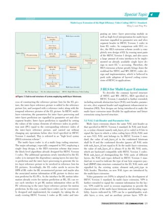
![scribes the number of layers and dependency relationship
among the layers. The dependency relationship indicates the
reference layers for inter⁃layer prediction when decoding the
current layer. In multi⁃layer extension, a layer can only refer⁃
ence lower layers. VPS signals the representation format for
each layer. VPS provides the information for bitstream confor⁃
mance and operation points, including profile, tier, level, layer
sets, hypothetical reference decoder (HRD) parameters, and
etc. Video usability information (VUI) for multi⁃layer bitstream
is also signalled in VPS.
Extension of sequence parameter set (SPS) for multi ⁃ layer
extension introduces only one syntax element in⁃
ter_view_mv_vert_constraint_flag, which is to signal whether
the vertical components of motion vectors used for inter⁃layer
prediction are constrained. Extension of picture parameter set
(PPS) for multi⁃layer extension includes parameters for picture
processing to derive inter ⁃ layer reference pictures, including
reference picture scaling offsets, reference region, reference
phase offsets and colour mapping.
3.2 LayerWise Decoding and Picture Order Count
(POC) Resetting
In SVC, the decoding process can only correctly start from
an access unit with all pictures coded as instantaneous decod⁃
ing refresh (IDR) pictures. At the encoder side, coding an ac⁃
cess unit with all IDR pictures always leads to an instanta⁃
neous bit⁃rate increment. By comparison, multi⁃layer extension
releases the constraint that the intra random access point
(IRAP) pictures are aligned within one access unit. A device
can start decoding a multi⁃layer bitstream from an access unit
with the BL picture being a random access picture, and make
an access to EL layers later, for example, when a random ac⁃
cess picture is in the EL layer.
Fig. 4 shows a multi ⁃ layer bitstream structure supporting
layer⁃wise decoding. The access unit AU(t4) is an access unit
with BL picture coded as a broken link access (BLA) picture.
The multi⁃layer decoder can make an access to the BL of this
multi⁃layer bitstream from AU(t4) first, and then access the EL
from AU(t8) in which the EL
picture is an IDR picture.
Note that in the example
shown in Fig. 4, the EL pic⁃
ture in AU(t4) is not decod⁃
able, because its temporal
reference picture in EL (i.e.
the EL picture in AU(t0)) is
not available when accessing
from AU(t4).
As with the HEVC Ver⁃
sion 1 standard, POC is used
in multi ⁃ layer extension to
represent the relative output
order of pictures within each
layer, and generally the derivation of POC value of a picture
does not depend on the POC values of pictures in other layers.
As IDR picture and BLA picture will force the complete POC
value or the most significant bits (MSB) of the POC to be 0, the
POC values of pictures within an access unit may be different
(e.g. BL and EL pictures in AU(t4) in Fig. 4), which violates
the constraint that the pictures in the same access unit have
the same POC value. To solve this, a POC resetting process is
designed for multi⁃layer extension, which resets the POC val⁃
ues for the pictures in an access unit when such pictures in dif⁃
ferent layers would get different POC values following the nor⁃
mal POC derivation process as specified in HEVC Version 1
standard [11]-[13]. In addition, to keep the consistency of the
POC differences in reference picture set (RPS) operations,
POC shifting operations are performed after resetting on previ⁃
ous pictures in decoding order as a decrement in POC values.
The parameters for POC resetting are signalled in slice seg⁃
ment header extension.
3.3 Hybrid Coding
Unlike SVC, which has the BL coded in H.264/AVC and
the BL bitstream embedded in the SVC bitsteam, multi⁃layer
extension enables the BL bitstream to be provided by external
means not specified in the second version of HEVC standard.
Furthermore, the BL bitstream provided by external means can
be generated by any single layer encoder besides HEVC, such
as H.264/AVC, MPEG⁃2, and etc. This feature of multi⁃layer
extension can be referred to as hybrid codec scalability or hy⁃
brid coding. In this case, decoding of the external BL is out the
scope of multi ⁃ layer extension, and hybrid coding is carried
out following the decoding operations of EL specified in multi⁃
layer extension by forwarding the reconstructed pictures after
decoding external BL to EL and inserted into the EL reference
lists for inter⁃layer prediction.
One use case for hybrid coding is long⁃term gradual upgrad⁃
ing a system by appending an HEVC EL to the existing stream
coded by other standards (e.g., MPEG⁃2, H.264/AVC). The
HEVC EL may provide higher resolution, higher dynamic
BL: the base layer EL: the enhancement layer
▲Figure 4. Example multi⁃layer bitstream structure with layer⁃wise decoding.
TRAIL_R
EL
BL
TRAIL_N
TRAIL_R
TRAIL_N
TRAIL_R
RADL_N
RADL_R
RADL_N TRAIL_N
IDR_W_
RADL
TRAIL_R
TRAIL_N
TRAIL_R
TRAIL_R
RADL_N
RADL_R
RADL_N TRAIL_N
TRAIL_R
TRAIL_N TRAIL_N
TRAIL_R
TRAIL_N
TRAIL_RBLA_W_
RADL
TRAIL_R
t0 t1 t2 t3 t4 t5 t6 t7 t8 t9 t10 t11 t12
Special Topic
Multi⁃Layer Extension of the High Efficiency Video Coding (HEVC) Standard
Ming Li and Ping Wu
February 2016 Vol.14 No.1ZTE COMMUNICATIONSZTE COMMUNICATIONS22](https://image.slidesharecdn.com/p020160311277843128165-160314232837/85/Emerging-Technologies-of-Future-Multimedia-Coding-Analysis-and-Transmission-26-320.jpg)
![range and/or wider color gamut to enhance the viewing quality
or provide a view other than the view represented by BL to
form a stereo pair for 3D viewing. Accordingly, the devices
with hybrid coding will provide more vivid viewing experience,
while legacy devices can still provide basic perceptual quality
by discarding the HEVC EL bits. The main advantage is that a
lot of bandwidth can be saved compared to simulcast solution
of two separate bitstreams while maintaining backward compat⁃
ibility during upgrade. However, the cost is that the devices
with hybrid coding need to support a number of standards and
conduct exact synchronization of HEVC EL pictures and BL
pictures in both inter⁃layer prediction and picture output pro⁃
cess (especially for stereo pair in 3D viewing).
3.4 Independent NonBase Layer (INBL)
Multi⁃layer extension supports INBL. The INBL is an EL in
multi⁃layer bitstream, which is coded without using inter⁃layer
prediction and conforms to a single layer profile. That is, the
only difference of an INBL and ordinary single layer bitstream
is that the nuh_layer_id in NAL units in INBL stream is not
equal to 0. In VPS, a flag is signalled along with profile, tier
and level of a layer to indicate whether this layer is an INBL.
INBL provides a simulcast layer in the multi⁃layer extension.
This flag is also used to signal the capability of a decoder
whether INBL can be processed, which is used in, for example,
session negotiation. An INBL rewriting process is also de⁃
signed for multi⁃layer extension to convert the INBL bitstream
extracted from multi⁃layer bitstream into a bitstream conform⁃
ing to a single layer profile.
4 Conclusions
This paper gives an overview of the concepts and HLS in
multi⁃layer extension of HEVC Version 1 standard. Multi⁃layer
extension is developed based on HEVC Version 1 standard
and serves as a common architecture for HEVC extensions us⁃
ing layered structure, including SHVC and MV⁃HEVC in the
second version of HEVC. High ⁃ level extension approach is
used to multi⁃layer extension without changing the block level
decoding operations already specified in single layer HEVC
profiles. This design principle enables the implementation of
SHVC and MV ⁃ HEVC to be built on existing single layer
HEVC codec with additional inter⁃layer reference picture pro⁃
cessing operations, which dramatically alleviates the workload
of codec design. Additionally, several new designs are also de⁃
veloped for multi⁃layer extension to achieve more flexibility for
applications and future extensions using layered structure. The
benefits of multi ⁃ layer extension will facilitate widespread
adoption of layered coding extensions of HEVC to applica⁃
tions.
Acknowledgment
The authors thank the experts of ITU ⁃ T VCEG, ISO/IEC,
MPEG, the ITU⁃T/ISO/IEC Joint Collaborative Team on Video
Coding (JCT⁃VC) and the ITU⁃T/ISO/IEC Joint Collaborative
Team on 3D Video Coding Extension Development (JCT⁃VC)
for their contributions.
Ming Li (li.ming42@zte.com.cn) received the BEng degree in telecommunication
engineering and PhD degree in communication and information systems from Xidi⁃
an University, China, in 2005 and 2010, respectively. He has been a standardiza⁃
tion engineer in video coding in ZTE since 2010. His current research interests in⁃
clude video coding and multimedia communication.
Ping Wu (ping.wu@zte.com.cn) received the BEng degree in Electrical Engineering
from Tsinghua University, Beijing, China in 1985 and received the PhD degree in
signal processing from Reading University, United Kingdom in 1993. From 1993 to
1997, he was a research fellow in the area of medical data processing in Plymouth
University, United Kingdom. From 1997 to 2008, he was a consultant engineer in
News Digital Systems Ltd, Tandberg Television, and Ericsson. He participated in
the development of ISO/IEC MPEG and ITU⁃T video coding standards. He also su⁃
pervised the engineering team to build the High Definition H.264 encoder products
for broadcasters. From 2008 to 2011, he joined Mitsubishi Electric Research Centre
Europe and continued to participate in High Efficiency Video Coding (HEVC) stan⁃
dard development with contributions in Call for Evidence and Call for Proposal.
From 2011, he has been a senior specialist in video coding in ZTE. He has many
technical proposals and contributions to the international standards on video coding
over past 18 years.
BiographiesBiographies
References
[1] High Efficiency Video Coding, ITU⁃T Recommendation H.265 standard v1, Apr.
2013.
[2] J. ⁃R. Ohm, G. J. Sullivan, H. Schwarz, T. K. Tan, and T. Wiegand,“Comparison
of the coding efficiency of video coding standards—including high efficiency vid⁃
eo coding (HEVC) ,”IEEE Transactions on Circuits and Systems for Video Tech⁃
nology, vol.22, no.12, pp. 1669- 1684, Dec. 2012. doi: 10.1109/TCS⁃
VT.2012.2221192.
[3] T. K. Tan, M. Mrak, V. Baroncini, and N. Ramzan,“Report on HEVC compres⁃
sion performance verification testing,”ITU, JCT⁃VC Document JCTVC⁃Q1011,
Mar. 2014.
[4] G. J. Sullivan, J. M. Boyce, Y. Chen, et al.,“Standardized extensions of high effi⁃
ciency video coding (HEVC),”IEEE Journal of Selected Topics in Signal Process⁃
ing, vol. 7, no. 6, pp. 1001- 1016, Dec. 2013. doi: 10.1109/JST⁃
SP.2013.2283657.
[5] High Efficiency Video Coding, ITU⁃T Recommendation H.265 standard v2, Oct.
2014.
[6] High Efficiency Video Coding, ITU⁃T Recommendation H.265 standard v3, Apr.
2015.
[7] R. Joshi, S. Liu, G. J. Sullivan, et al.,“HEVC screen content coding draft text
4,”ITU, JCT⁃VC Document JCTVC⁃V1005, Oct. 2015.
[8] K. Minoo, P. Yin, T. Lu, et al.,“Exploratory test model for HDR extension of
HEVC,”MPEG Document N15792, Oct. 2015.
[9] Advanced Video Coding for Generic Audiovisual Services, ITU⁃T Recommendation
H.264, Jun. 2011.
[10] L. Guo, Y. He, D.⁃K. Kwon, et al.,“TE 2: summary report on inter⁃layer texture
prediction signaling in SHVC”, ITU, JCT⁃VC Document JCTVC⁃L0022, Jan.
2013.
[11] Y. Chen, Y.⁃K. Wang, and A. K. Ramasubramonian,“MV⁃HEVC/SHVC HLS:
cross⁃layer POC alignment,”ITU, JCT⁃VC Document JCTVC⁃N0244 & JCT⁃
3V Document JCT3V⁃E0075, Jul. 2013.
[12] G. J. Sullivan,“JCT⁃VC AHG report: multi⁃layer picture order count derivation
(AHG10),”ITU, JCT⁃VC Document JCTVC⁃P0010, Jan. 2014.
[13] Hendry Fnu, A. K. Ramasubramonian, Y.⁃K. Wang, et al.,“MV⁃HEVC/SHVC
HLS: on picture order count,”ITU, JCT⁃VC Document JCTVC⁃P0041 & JCT⁃
3V Document JCT3V⁃G0031, Jan. 2014.
Manuscript received: 2015⁃11⁃10
Multi⁃Layer Extension of the High Efficiency Video Coding (HEVC) Standard
Ming Li and Ping Wu
Special Topic
February 2016 Vol.14 No.1 ZTE COMMUNICATIONSZTE COMMUNICATIONS 23](https://image.slidesharecdn.com/p020160311277843128165-160314232837/85/Emerging-Technologies-of-Future-Multimedia-Coding-Analysis-and-Transmission-27-320.jpg)
![SHVC, the Scalable Extensions of HEVC,SHVC, the Scalable Extensions of HEVC,
and Its Applicationsand Its Applications
Yan Ye1
, Yong He1
, YeKui Wang2
, and Hendry2
(1. InterDigital Communications, Inc., San Diego, CA 92121, USA;
2. Qualcomm Incorporated, San Diego, CA 92121, USA)
Abstract
This paper discusses SHVC, the scalable extension of the High Efficiency Video Coding (HEVC) standard, and its applications in
broadcasting and wireless broadband multimedia services. SHVC was published as part of the second version of the HEVC specifi⁃
cation in 2014. Since its publication, SHVC has been evaluated by application standards development organizations (SDOs) for its
potential benefits in video applications, such as terrestrial and mobile broadcasting in ATSC 3.0, as well as a variety of 3GPP mul⁃
timedia services, including multi⁃party multi⁃stream video conferencing (MMVC), multimedia broadcast/multicast service (MBMS),
and dynamic adaptive streaming over HTTP (DASH). This paper provides a brief overview of SHVC and the performance and com⁃
plexity analyses of using SHVC in these video applications.
HEVC; SHVC; broadcasting; video conferencing; video streaming
Keywords
DOI: 10.3969/j. issn. 16735188. 2016. 01. 004
http://www.cnki.net/kcms/detail/34.1294.TN.20160122.1848.004.html, published online January 22, 2016
Special Topic
H
February 2016 Vol.14 No.1ZTE COMMUNICATIONSZTE COMMUNICATIONS24
1 Introduction
igh ⁃ Efficiency Video Coding (HEVC) [1] is the
state⁃of⁃the⁃art video coding standard developed
by the Joint Collaborative Team on Video Coding
(JCT⁃VC) of ISO/IEC JTC 1 SC 29/WG 11 MPEG
and ITU⁃T Q6/16 VCEG. Finalized in January 2013, the first
version of HEVC achieved more than 50% bit rate reduction
over its predecessor H.264/MPEG⁃4 part 10 Advanced Video
Coding (H.264/AVC) [2] at comparable subjective quality [3].
An overview of HEVC can be found in [4].
The first version of HEVC provides support for temporal
scalability. To support other types of scalabilities, such as spa⁃
tial scalability and quality scalability, the ISO/IEC MPEG and
ITU⁃T VCEG issued a joint call for proposals [5] for scalable
video coding extensions of HEVC (SHVC) in July 2012. In Oc⁃
tober 2012, twenty responses were received from companies,
research institutes, and universities worldwide, and the devel⁃
opment of the SHVC standard officially started. In July 2014,
SHVC was finalized as part of the second version of HEVC [6],
[7], which also includes the multiview extensions of HEVC (MV⁃
HEVC) and the range format extensions of HEVC (RExt). An
SHVC test model document describing the non⁃normative as⁃
pects of SHVC, including encoder description, as well as the
reference software continued to evolve after the normative SH⁃
VC specification was finalized. The latest SHVC test model
(SHM 10) document and reference software can be found in [8]
and [9], respectively. The common conditions under which the
performance of SHVC is tested can be found in [10].
In recent years, video entertainment habits have changed
significantly. Smartphones, tablets, and other portable devices
are equipped with increasingly more powerful computing capa⁃
bilities and faster network connections. These devices provide
rich platforms for video and multimedia applications. Instead
of sitting in front of the TV and watching pre⁃scheduled pro⁃
grams provided by free ⁃ to ⁃ air or cable networks, people are
spending more time consuming video content on⁃demand
through a wide variety of devices, such as living room TVs,
smartphones, tablets, and laptops. The N ⁃ screen scenario,
where video content is generated from and distributed to differ⁃
ent terminals with a wide range of capabilities, has become
common. Furthermore, more collaboration and communication
in the workplace and at home involves video chat, multi⁃party
video conferencing, and telepresence. In light of the significant
increase in device and network heterogeneity, scalable video
coding can potentially make networks more efficient and resil⁃
ient to errors. For this reason, since SHVC was finalized in
2014, various application standards development organizations
(SDOs) have quickly taken up the tasks of evaluating the poten⁃
tial benefits of supporting SHVC in their applications.
The Advanced Television Standardization Committee
(ATSC) was established in the early 1980s. The most widely](https://image.slidesharecdn.com/p020160311277843128165-160314232837/85/Emerging-Technologies-of-Future-Multimedia-Coding-Analysis-and-Transmission-28-320.jpg)
![SHVC, the Scalable Extensions of HEVC, and Its Applications
Yan Ye, Yong He, Ye⁃Kui Wang, and Hendry
Special Topic
February 2016 Vol.14 No.1 ZTE COMMUNICATIONSZTE COMMUNICATIONS 25
used standard developed by ATSC is ATSC1.0, which is used
for digital television transmission in the United States, Canada,
Mexico, South Korea, and a few other North and South Ameri⁃
can countries. Since 2013, the committee has been developing
the ATSC 3.0 standard, with the goal of providing more servic⁃
es to the viewer with increased bandwidth efficiency and better
compression. Because broadcasters need to transmit video pro⁃
grams in a variety of formats, including standard definition
(SD) [11], high definition (HD) [12], and ultra⁃high definition
(UHD) [13], scalable video coding can provide better coding ef⁃
ficiency compared to transmitting these various video formats
independently using simulcast. After careful review of the cod⁃
ing performance and complexity of SHVC, the committee re⁃
cently decided to adopt the support of SHVC into ATSC 3.0.
Commercial deployment of ATSC 3.0 is expected to emerge
within the next few years.
The 3GPP is a collaboration between groups of telecommuni⁃
cations associations. 3GPP has developed a number of mobile
communications standards that are widely deployed around the
globe, including GSM, Universal Mobile Telecommunications
System (UMTS), High Speed Packet Access (HSPA), and most
recently, 4G Long Term Evolution (LTE). 3GPP SA WG4 Co⁃
dec (SA4) specifies speech, audio, video, and multimedia co⁃
decs in both circuit ⁃ switched and packet ⁃ switched environ⁃
ments. As mobile and portable devices become main consump⁃
tion platforms for video and multimedia applications, much
pressure is put on wireless network operators to provide rich
multimedia experience to a wide range of devices with maxi⁃
mum bandwidth efficiency. Scalable video coding can increase
the ability of service providers to adapt to the capabilities of
customer devices and fluctuating network conditions. Scalable
video coding can also provide better error resilience because it
combines naturally with unequal error protection mechanisms
to better combat error⁃prone wireless channels. For this rea⁃
son, 3GPP SA4 established a video⁃enhancements study item
with a focus on the performance and complexity of SHVC in a
number of mobile video applications, including multiparty mul⁃
tistream video conferencing (MMVC), multimedia broadcast/
multicast service (MBMS), and 3GPP dynamic adaptive stream⁃
ing over HTTP (3GP⁃DASH).
The remainder of this paper is organized as follows. In sec⁃
tion 2, SHVC architecture is briefly reviewed. In section 3, the
performance of SHVC for terrestrial and mobile broadcasting
in ATSC 3.0 is discussed. In section 4, the performance of SH⁃
VC for a number of 3GPP video applications is discussed. Sec⁃
tion 5 concludes the paper.
2 SHVC
In scalable video coding, interlayer prediction (ILP) is a
powerful tool for improving the coding efficiency of enhance⁃
ment layers (ELs). ILP involves predicting an EL picture using
a base layer (BL) or another lower reference layer picture.
Take a two⁃layer scalable coding system that consists of one
BL and one EL for example. SHVC uses the so⁃called“refer⁃
ence index”framework for efficient ILP. In the reference index
framework, the reconstructed picture of the BL is treated as an
interlayer reference picture (ILRP). The existing reference in⁃
dex signaling that is already part of the single⁃layer HEVC co⁃
dec is used to identify whether the block⁃level prediction
comes from the BL or current EL. Such an ILP method is simi⁃
lar in principle to the multiview extension of H.264/AVC (An⁃
nex H in [2], also commonly referred to as MVC) and MV ⁃
HEVC. This reference⁃index⁃based framework of SHVC is fun⁃
damentally different from its predecessor, the scalable exten⁃
sion of H.264/AVC (Annex G in [2], also commonly referred to
as SVC), which instead relies on a block⁃level flag to indicate
whether an EL block is predicted from the BL or current EL.
Fig. 1 shows the SHVC codec architecture from the decoder’s
perspective using a two⁃layer system as an example. The BL re⁃
construction is retrieved from the BL decoded picture buffer
(BL DPB). If necessary, appropriate interlayer processing is
done to the reconstructed BL picture to obtain the interlayer
reference picture. The ILRP is put into the EL DPB as a long⁃
term reference picture and is used with the EL temporal refer⁃
ence pictures for EL coding.
There are a number of design benefits with the reference in⁃
dex framework. First, all block⁃level logic of the EL codec is
kept the same as that of a single⁃layer HEVC codec. Changes
made to support the EL codec are limited to the slice header
level and above; in other words, they are limited to the high⁃
level syntax (HLS). Therefore, the EL decoder is labelled an
HEVC decoder* (Fig. 1). Making HLS⁃only changes enables
the existing ASIC design of an HEVC codec to be reused to the
greatest possible extent to implement an SHVC codec. Second,
the BL codec in Fig. 1 can operate as a black box because the
scalable coding of the EL only requires the reconstructed BL
pictures. This allows earlier⁃generation codecs, such as H.264/
AVC, to be used in the BL for backward compatibility. The
more efficient HEVC codec is used in the EL to improve cod⁃
AVC: Advanced Video Coding
BL: base layer
DPB: decoded picture buffer
EL: enhancement layer
HEVC: High⁃Efficiency Video Coding
SHVC: scalable video coding extensions of HEVC
▲Figure 1. SHVC decoder architecture with two layers. The EL
decoder has the same block⁃level logic as a single⁃layer HEVC decoder.
HEVC decoder*
SHVC
bitstream
EL video output
EL DPB
Inter layer
processing
Demux
Base layer decoder
(HEVC, AVC, etc)
BL DPB
EL stream
BL stream
BL video output](https://image.slidesharecdn.com/p020160311277843128165-160314232837/85/Emerging-Technologies-of-Future-Multimedia-Coding-Analysis-and-Transmission-29-320.jpg)
![Special Topic
SHVC, the Scalable Extensions of HEVC, and Its Applications
Yan Ye, Yong He, Ye⁃Kui Wang, and Hendry
February 2016 Vol.14 No.1ZTE COMMUNICATIONSZTE COMMUNICATIONS26
ing performance. Finally, the scalable system in Fig. 1 is com⁃
patible with MV⁃HEVC. Although SHVC and MV⁃HEVC start⁃
ed out as different efforts, a unified architecture of the two ex⁃
tensions is desirable. Once one of these two has been imple⁃
mented, the other can be easily added, and this can increase
the chances that both extensions will be commercially used.
In terms of computation complexity, the architecture in Fig.
1 is based on the multi⁃loop decoding design. This means that
all lower reference layers need to be fully reconstructed to de⁃
code the current EL, and decoding complexity is higher than
that of the single⁃loop decoding design in SVC [14]. More de⁃
tailed reviews of the SHVC standard and HEVC extensions
can be found in [15]-[17].
3 SHVC in ATSC 3.0
3.1 ATSC 3.0
In the past, delivery of video entertainment to the consumer
was relatively simple and controlled, and involved broadcast⁃
ers or content producers sending TV signals at prescheduled
times to the living room. Today, people watch video on⁃demand
on a wide variety of devices at a time and place of their choice.
The delivery paths may be over⁃the⁃air, cable or satellite, Inter⁃
net, local storage, or a combination of these. ATSC 3.0 is the
next ⁃ generation broadcast standard designed to address this
need. It uses advanced transmission, including hybrid broad⁃
cast and broadband, as well as advanced video/audio coding
techniques to bring new, creative services to viewers [18].
The next⁃generation ATSC 3.0 broadcast system is designed
to increase service flexibility and enable terrestrial broadcast⁃
ers to send hybrid⁃content services to fixed and mobile receiv⁃
ers in a seamless manner. It combines both over⁃the⁃air trans⁃
mission and broadband delivery. Other essential features in⁃
clude support for multiscreen and the flexibility to choose
among SD, HD and UHD resolutions. SHVC provides an effi⁃
cient solution when different spatial resolutions need to be
transmitted by the content provider at the same time.
The work on ATSC 3.0 is organized according to layers,
such as the physical layer, management and protocol layer,
and application and presentation layer. Video coding, audio
coding, and run⁃time environment are addressed by the appli⁃
cation and presentation layer. Support for UHD and HD is key
for video coding — 4K support at the start and potentially 8K
support via future extensions. Portable, handheld, vehicular,
and fixed devices (both indoors and outdoors) are all targeted,
and hybrid integration of broadcast and broadband delivery is
required. This paper mainly focuses on the work by ATSC S34⁃
1, the ad hoc group for video for ATSC 3.0. A general overview
of ATSC 3.0 and all ATSC 3.0 groups can be found in [19].
3.2 SHVC Performance with ATSC 3.0
Video requires support for UHD and HD; support for porta⁃
ble, mobile, vehicular, and fixed devices operating in indoors
or outdoors; and support for hybrid broadcast/broadband deliv⁃
ery. The following four scenarios were identified for ATSC 3.0
deployment:
1) larger coverage area (scenario A). Receivers in a first class
are fixed within the current ATSC 1.0 coverage area, and re⁃
ceivers in a second class are fixed but are not within the cov⁃
erage area (e.g., rural, or with an indoor or integrated anten⁃
na).
2) pedestrian phone or tablet (scenario B). Receivers in a first
class are handheld and moving at pedestrian speeds (possi⁃
bly indoors), and receivers in a second class are stationary.
3) mobile⁃enabled (scenario C). Receivers in a first class are
moving at relatively high speed, and receivers in a second
class are stationary.
4) tablet in bedroom (scenario D). Receivers in a first class are
indoors and are portable, and receivers in a second class are
stationary.
SHVC was evaluated in each of these four cases, with the
main focus on spatial scalability; i.e., the base layer could be
optimized for mobile reception and the enhancement layer
could be optimized for up to 4K resolution. These four scenari⁃
os were proposed and agreed upon by S34⁃1 to be used as com⁃
mon test conditions for comparing the performance of SHVC
with HEVC simulcast. In each scenario, three different physi⁃
cal⁃layer pipes (PLPs)—PLP⁃1, PLP⁃2 and PLP⁃3—were as⁃
sumed for transmitting high⁃quality video, low⁃quality video,
and audio (and miscellaneous information), respectively. The
video resolution, spectral efficiency, and coded bit rate for
each PLP and each scenario are summarized in Table 1. In all
four scenarios, the sum of bandwidths of all PLPs (after spec⁃
tral efficiency has been taken into account) does not exceed 6
Mbps. The detailed test conditions can be found in [19].
To make a meaningful comparison, both HEVC and SHVC
▼Table 1. ATSC 3.0 common test conditions for SHVC
Scenario
A
B
C
D
Configuration
Resolution
Spectral Efficiency (b/s/Hz)
Bit rate (Mbps)
Resolution
Spectral Efficiency (b/s/Hz)
Bit rate (Mbps)
Resolution
Spectral Efficiency (b/s/Hz)
Bit rate (Mbps)
Resolution
Spectral Efficiency (b/s/Hz)
Bit rate (Mbps)
PLP⁃1
UHD (2160)
4.0
15.1
HD (1080)
2.23
5.0
HD (1080)
4.0
5.0
UHD
7.1
4.5
PLP⁃2
HD (1080)
2.67
5.0
HD (720)
1.0
3.46
qHD (540)
0.44
1.7
HD
0.59
2.75
PLP⁃3
Audio/misc.
1.31
0.47
Audio/misc.
1.0
0.3
Audio/misc.
0.44
0.34
Audio
0.44
0.3
HD: high definition
PLP: physical⁃layer pipe
qHD: quarter high definition
UHD: ultra⁃high definition](https://image.slidesharecdn.com/p020160311277843128165-160314232837/85/Emerging-Technologies-of-Future-Multimedia-Coding-Analysis-and-Transmission-30-320.jpg)
![Special Topic
February 2016 Vol.14 No.1 ZTE COMMUNICATIONSZTE COMMUNICATIONS 27
were coded using configurations that were as similar as possi⁃
ble. The hierarchical B configuration following the SHVC com⁃
mon test condition in JCT⁃VC [10] was used, with the random
access point period of 0.5 seconds for the BL and 0.5 seconds
or 4 seconds for the EL. The quality range was controlled by
using a PSNR of between 38 dB and 42 dB, the typical operat⁃
ing quality for broadcasters. The bit rates of both layers were
controlled so that they were no higher than those listed in Ta⁃
ble 1.
Fig. 2 shows the performance of SHVC and HEVC simul⁃
cast for each scenario. Two types of savings were calculated: 1)
the percentage of average video bit rate savings, which is how
much SHVC reduces the coded video bit rate compared to si⁃
mulcast while maintaining the same quality (PSNR); and 2) the
percentage of average channel utilization savings, which is cal⁃
culated by converting bit rate savings into actual channel utili⁃
zation savings by taking into account the different spectral effi⁃
ciencies for each PLP.
In general, SHVC provides 40%-47% video bit rate savings
in the four scenarios and 6%-37% channel utilization savings
in the four scenarios when spectral efficiency is taken into ac⁃
count. Channel utilization is inversely proportional to the spec⁃
tral efficiency factors in Table 1. In the ATSC tests, the BL bit
rates were fixed; therefore, the spectral efficiency for the BL
(PLP⁃2) does not have any effect. A bigger spectral efficiency
factor for the EL (PLP⁃1) will translate the same amount of bit
rate saving into less channel utilization saving. This is why the
channel utilization savings for scenario D with the PLP⁃1 spec⁃
tral efficiency of 7.1 is significantly less than that of scenario
A with PLP⁃1 spectral efficiency of 4.0. The detailed perfor⁃
mance comparison can be found in [20].
4 SHVC in 3GPP SA4
4.1 3GPP SA4
SA4 is the 4th working group of the 3GPP Technical Specifi⁃
cation Group of Service and System Aspects (TSG⁃SA). SA4 is
responsible for development of 3GPP standards that handles
media codecs and related aspects. In particular, SA4 has speci⁃
fied the media handling aspects of all 3GPP multimedia ser⁃
vice standards, including 3GP⁃DASH in TS 26.247 [21], Pack⁃
et⁃switched Streaming Service (PSS) in TS 26.234 [22], MBMS
in TS 26.346 [23], Multimedia Telephony Service over IMS
(MTSI) in TS 26.114 [24] (this also includes MMVC), Multime⁃
dia Messaging Service (MMS) in TS 26.140 [25], IMS Messag⁃
ing and Presence in TS 26.141 [26], and IMS based Telepres⁃
ence in TS 26.223 [27].
For each of these multimedia services, the selection of me⁃
dia codecs to be supported is important. Support for H.264/
AVC in 3GPP multimedia services was decided in 2004, e.g.,
it was first included in TS 26.234 in v6.1.0 dated in September
2004. SVC was studied in 2010 and the result was included in
TR 26.904 [28]; it was decided not to specify SVC support in
the 3GPP multimedia services. For HEVC, a specific work
item was agreed by SA4 in August 2012, and a study was per⁃
formed comparing HEVC with H.264/AVC and documented in
TR 26.906 [29]. For SHVC, a study item was agreed by SA4 in
November 2014, focusing on evaluation of SHVC versus
HEVC simulcast for three of the 3GPP multimedia services:
the MMVC part of MTSI, MBMS, and 3GP⁃DASH. The use cas⁃
es and simulations for MMVC happened to apply to the telep⁃
resence service. This study was completed in November 2015.
An overview of the SHVC use cases, simulation results, and
complexity analyses is provided in the following subsections.
4.2 Using SHVC for MMVC and Telepresence
The performance of SHVC was evaluated for the MMVC and
telepresence use cases in 3GPP SA4 [30]. The use case consid⁃
ers video conferencing with multiple participating user equip⁃
ment (UE) with different decoding and display capabilities.
The multimedia resource function processor (MRFP) connects
multiple video conferencing endpoints, receives video streams
from each endpoint, and forwards a set of appropriate video
streams to each endpoint.
Fig. 3 illustrates an example of such use case with four UEs
in the video conferencing session, where UE⁃A and UE⁃D are
high⁃end devices and UE⁃B and UE⁃C are low⁃end devices.
Each UE displays a full video of the active speaker and a num⁃
SHVC, the Scalable Extensions of HEVC, and Its Applications
Yan Ye, Yong He, Ye⁃Kui Wang, and Hendry
▲Figure 2. SHVC vs. HEVC simulcast. ▲Figure 3. The use case for MMVC and telepresence.
A B C D
Scenarios
Bitrate savings Channel utilization savings
50%
45%
40%
35%
30%
25%
20%
15%
10%
5%
0%
Percentageofsavings
High⁃end device
B
“previous active speaker”A
“Active speaker”
Low⁃end deviceC
MRFP
DHigh⁃end device
Low⁃end device
MRFP:multimedia resource function processor](https://image.slidesharecdn.com/p020160311277843128165-160314232837/85/Emerging-Technologies-of-Future-Multimedia-Coding-Analysis-and-Transmission-31-320.jpg)
![Special Topic
February 2016 Vol.14 No.1ZTE COMMUNICATIONSZTE COMMUNICATIONS28
ber of thumbnails of all other participants, while the active
speaker displays the previous active speaker as full video. In
Fig. 3, UE⁃A is the current active speaker sending a high video
resolution and a medium video resolution to the MRFP. The
high⁃resolution video is forwarded to participants with a high⁃
end device (UE ⁃ D), and the medium resolution video is for⁃
warded to participants with a low⁃end device (UE⁃B and UE⁃
C). The current active speaker (UE ⁃ A) receives the medium
resolution video from the previous active speaker (UE⁃B). Each
UE except the active speaker receives either high⁃resolution or
medium⁃resolution video of the active speaker from the MRFP
and sends a low⁃resolution thumbnail video to the MRFP to be
displayed by other UEs.
For HEVC simulcast, on the uplink side, UE⁃A sends one
high⁃resolution video bitstream and one medium⁃resolution vid⁃
eo bitstream to the MRFP, UE⁃B sends a medium⁃resolution
video bitstream and a thumbnail video bitstream to the MRFP,
and UE ⁃ C and UE ⁃ D each sends a thumbnail video to the
MRFP. On the downlink side, each UE except the active speak⁃
er receives one high⁃ or medium⁃resolution video bitstream of
the active speaker depending on the device capability for full
video display, and a thumbnail video bitstream from each of
the other UEs for thumbnail display. The active speaker re⁃
ceives the medium⁃resolution video bitstream of the previous
active speaker for full video display, and a thumbnail video bit⁃
stream from each of the other UEs for thumbnail display.
For SHVC, on the uplink side, UE⁃A sends a two⁃layer SH⁃
VC bitstream with BL at medium resolution and EL at high res⁃
olution to the MRFP. UE⁃B sends a two⁃layer SHVC bitstream
with BL at thumbnail resolution and EL at medium resolution
to the MRFP. UE⁃C and UE⁃D each sends an HEVC single lay⁃
er thumbnail video bitstream to the MRFP. On the downlink
side, UE⁃A receives a two⁃layer SHVC bitstream from UE⁃B
for full video display, and two HEVC single⁃layer bitstreams
from UE⁃C and UE⁃D for thumbnail display. UE⁃B receives
the extracted BL bitstream from UE⁃A for full video display,
and two HEVC bitstreams from UE⁃C and UE⁃D for thumbnail
display. UE⁃C receives one extracted BL bitstream from UE⁃A
for full video display, one extracted BL bitstream from UE⁃B
for thumbnail display, and one HEVC single ⁃ layer bitstream
from UE⁃D for thumbnail display. UE⁃D receives one two⁃layer
SHVC bitstream from UE⁃A for full video display, one extract⁃
ed BL bitstream from UE ⁃ B for thumbnail display, and one
HEVC single⁃layer bitstream from UE⁃C for thumbnail display.
In the simulations, the high video resolution was 1080p, the
medium video resolution was 720p, and thumbnail video reso⁃
lution was 240p.
Table 2 shows the SHVC rate savings on the uplink and
rate penalty on the downlink, for each participant. On the up⁃
link, UE ⁃ A saves on average 27.3% bandwidth, and UE ⁃ B
saves on average 5.5% bandwidth. On the downlink, because
the two ⁃ layer bitstream needs to be received when SHVC is
used, UE⁃A’s downlink bandwidth increases by 11.6%, UE⁃D’s
downlink bandwidth increases by 23.5%. For UE⁃C and UE⁃D,
the uplink bandwidth usage is identical, regardless of the co⁃
dec choice. The same is true for downlink bandwidth usage for
UE⁃B and UE⁃C.
In general, SHVC provides uplink bandwidth savings for
UEs that are sending more than one video resolution, and in⁃
curs downlink bandwidth penalty for UEs that are receiving
the high⁃resolution video. Further detailed results can be
found in [30]-[33].
4.3 Using SHVC for MBMS
The MBMS case is referred to as the differentiated⁃service
MBMS use case [33]. For this use case, it is assumed that two
different classes of video services may be provided (more class⁃
es of video service is possible but could pose burden for any
broadcast system), e.g., the normal video service of 720p and
the premium video service of 1080p. UEs may subscribe to ei⁃
ther of the two services depending on their decoding and ren⁃
dering capabilities, network access conditions, power saving
strategies, price, and/or other considerations. UEs receiving
the normal service receive and render the lower quality video
with lower resolution, and UEs receiving the premium service
receive and render the higher quality video with higher resolu⁃
tion. The same scenario is also applicable to evolved MBMS
(eMBMS), which allows broadcast over the LTE network. Due
to the fact that only the broadcast mode can be used in
eMBMS, all bits required for both services are assumed to be
transmitted on all the network paths, from the content provider
to the Broadcast⁃Multicast Service Centre (BM⁃SC), from the
BM⁃SC to MBMS Gateway (MBMS⁃GW), from MBMS⁃GW to
evolved Node B (eNodeB), as well as the air interface between
eNodeB and UEs, as shown in Fig. 4.
When SHVC is used in the differentiated⁃service MBMS use⁃
case, the content is encoded with two layers of different spatial
resolutions, and is transmitted from the content provider to the
BM⁃SC, and all the way to the UEs. Each premium⁃service UE
receives and decodes both layers and renders the higher layer,
while each normal⁃service UE receives, decodes, and renders
the base layer only.
The performance of SHVC was evaluated for the MBMS use
case against HEVC simulcast. Five test sequences with 720p
for the BL and 1080p for the EL were used. For HEVC simul⁃
cast, the bandwidth for transmission from the content provider
to the BM⁃SC, and all the way to the UEs is the bandwidth re⁃
quired for transmitting one HEVC coded 1080p bitstream and
SHVC, the Scalable Extensions of HEVC, and Its Applications
Yan Ye, Yong He, Ye⁃Kui Wang, and Hendry
▼Table 2. Uplink and downlink rate saving comparison for
MMVC/telepresence
UE: user equipment
Average uplink bandwidth saving
Average downlink bandwidth cost
UE⁃A
27.3%
11.6%
UE⁃B
5.5%
0%
UE⁃C
0%
0%
UE⁃D
0%
23.5%](https://image.slidesharecdn.com/p020160311277843128165-160314232837/85/Emerging-Technologies-of-Future-Multimedia-Coding-Analysis-and-Transmission-32-320.jpg)
![one HEVC coded 720p bitstream. In the simulations, video bit⁃
streams were encoded with a random access coding structure
to achieve the highest compression efficiency. Furthermore, to
enable stream switching or late tuning⁃in and channel switch⁃
ing in MBMS, intra random access point (IRAP) picture is cod⁃
ed once every two seconds. Further details of the simulation
condition can be found in [33]. The performance of SHVC com⁃
pared to HEVC simulcast for the MBMS use case in terms of
bandwidth reduction, decoding complexity and encoding com⁃
plexity are summarized as follows (further details can be found
in [33], [34]):
1) In term of bandwidth reduction, the use of SHVC provides
an average bandwidth reduction around 32.9% when com⁃
pared to HEVC simulcast.
2) The decoding complexity overhead at UEs depends on how
many layers an UE needs to decode. The decoding complexi⁃
ty for UEs receiving normal⁃service when SHVC is used can
be assumed the same as when HEVC simulcast is used be⁃
cause UEs receiving normal⁃service can ignore coded data
for enhancement layer. The decoding complexity overhead
for UEs receiving the premium⁃service when SHVC is used
is roughly the percentage of the number of samples in the
lower resolution video relative to that in the higher resolu⁃
tion video.
3) Compared with simulcast, SHVC encoding may be less com⁃
plex than simulcast encoding because SHVC places the zero⁃
motion constraint on inter layer prediction. When the inter⁃
layer reference picture provides a sufficiently good predic⁃
tion signal (without the need for motion estimation), early ter⁃
mination is typically applied at the encoder, and the need
for motion estimation of the temporal reference pictures is
avoided, leading to lower encoding complexity.
4.4 Using SHVC for the 3GPDASH Use Case
The use case scenario the 3GP⁃DASH video streaming ser⁃
vices involves a diverse of end user devices which could have
different display capabilities and network access conditions
[33]. Each UE may prefer to receive a different quality of con⁃
tent, possibly with a different resolution, and request the cho⁃
sen video content from the origin server, involving cache serv⁃
ers between the origin server and the UE. During a session, an
UE may also adaptively switch to segments of different repre⁃
sentations of different bit rates and qualities and possibly also
different spatial resolutions to adapt to the dynamic network
conditions. Video content is encoded into multiple video
streams in different representations providing different levels
of resolutions or qualities, e.g., as three representations of reso⁃
lutions 360p, 720p and 1080p (Fig. 5). Copies of the streams
may be stored in the cache servers and directly served to the
UEs.
When SHVC is used, multiple resolutions or quality repre⁃
sentations can be encoded into multi⁃layer SHVC bitstreams.
Each layer can be encapsulated as one 3GP⁃DASH representa⁃
Special Topic
February 2016 Vol.14 No.1 ZTE COMMUNICATIONSZTE COMMUNICATIONS 29
SHVC, the Scalable Extensions of HEVC, and Its Applications
Yan Ye, Yong He, Ye⁃Kui Wang, and Hendry
▲Figure 4. The use case for MBMS.
BM⁃SC: Broadcast⁃Multicast Service Centre
MBMS⁃GW: multimedia broadcast/multicast service gateway
UE: user equipment
▲Figure 5. The use case for 3GP⁃DASH.
Premium⁃service UEs
Normal⁃service UEs eNodeB
eNodeB
eNodeB
BM⁃SC/
MBMS⁃GW
Content
provider
Video
encoder
Origin server
Video
encoder
Video
encoder
Cache server
Cache server
Cache server](https://image.slidesharecdn.com/p020160311277843128165-160314232837/85/Emerging-Technologies-of-Future-Multimedia-Coding-Analysis-and-Transmission-33-320.jpg)
![tion. A client wanting a particular resolution or quality can re⁃
quest segments of that representation and all other representa⁃
tions it depends on (i.e., request the desired layer and all lay⁃
ers the desired layer depends on). The desired layer and all its
dependent layers are then sent to the client, which decodes the
bitstream and outputs the desired layer.
The performance of SHVC was evaluated for the 3GP⁃DASH
use case against HEVC simulcast. The simulations were con⁃
ducted with three representations of spatial resolution 360p,
720p and 1080p, the random access coding structure, and one
IRAP picture every two and four seconds. Further details of
the simulation condition can be found in [33]. The perfor⁃
mance of SHVC compared to HEVC simulcast from the as⁃
pects of required bandwidth for transmission, decoding com⁃
plexity and encoding complexity are as follows (further details
can be found in [33] and [35]):
1) For outgoing transmission bandwidth, i.e., bandwidth re⁃
quired for transmission of encoded content from the origin
server to cache servers and from the origin server to UEs,
compared to HEVC simulcast SHVC requires less band⁃
width for transmitting the encoded streams from the origin
server to cache and to UEs. The bandwidth reduction varies
from 9.2% to 10.5% for transmitting both the 360p and
720p bitstreams and from 23.3% to 23.6% for transmitting
all the 360p, 720p and 1080p bitstreams. In addition to sav⁃
ing the outgoing bandwidth, the same amount of savings can
be achieved on the storage requirements for the origin server
and the cache servers. For incoming transmission band⁃
width, i.e., bandwidth required by UEs to receive the encod⁃
ed content, SHVC incurs data overhead for UEs when receiv⁃
ing the medium or high resolution representation. The over⁃
head varies from 20.4% to 22.1% when receiving the 720p
resolution and from 24.9% to 26.9% when receiving the
1080p.
2) The decoding complexity is mainly proportional to the reso⁃
lution(s) of the video represented in the bitstream. For
HEVC simulcast, only one single layer stream needs to be
decoded, i.e., one of the three bitstreams of 360p, 720p and
1080p. For SHVC, the decoding complexity depends on the
resolution of each layer that needs to be decoded in order to
output the highest layer video resolution.
3) For HEVC simulcast, the content provider has to encode in⁃
dependent bitstreams of different spatial resolutions. For SH⁃
VC, the content provider has to encode a bitstream with mul⁃
tiple layers in which each layer is associated with one spa⁃
tial resolution. Compared to simulcast, the complexity of SH⁃
VC encoding may be less than that of simulcast encoding for
the same reason as discussed in the MBMS use case.
5 Conclulsions
In this paper, a brief overview of SHVC, the latest scalable
video coding standard based on HEVC, was provided. Several
use cases for SHVC, as were recently studied by application
SDOs including ATSC and 3GPP SA4, were reviewed. In the
broadcasting and multicasting cases, SHVC saves transmission
bandwidth. In the video conferencing and telepresence cases,
SHVC saves uplink bandwidth but increases the downlink rate
for high ⁃ end devices. In the DASH ⁃ based video streaming
case, SHVC saves server storage and outgoing transmission
bandwidth but increases incoming transmission bandwidth for
devices receiving representations with higher bit rates, picture
rates, spatial resolutions and so on. The decoding complexity
for clients processing an SHVC bitstream is higher than that
for clients processing a corresponding HEVC bitstream in si⁃
mulcast, whereas the encoding complexity is typically lower.
SHVC was recently included in the ATSC 3.0 standard based
on the significant channel utilization savings it can provide for
the broadcasters. 3GPP concluded that SHVC can provide
technical benefits in different scenarios and circumstances and
may be an attractive codec solution whenever new use cases
and scenarios are considered within emerging 3GPP multime⁃
dia services. However, a normative specification of SHVC sup⁃
port in a 3GPP Release 13 multimedia service standard has
not been included.
Special Topic
February 2016 Vol.14 No.1ZTE COMMUNICATIONSZTE COMMUNICATIONS30
SHVC, the Scalable Extensions of HEVC, and Its Applications
Yan Ye, Yong He, Ye⁃Kui Wang, and Hendry
References
[1] High Efficiency Video Coding, Rec. ITU⁃T H.265 and ISO/IEC 23008⁃2, Version
1⁃3, Apr. 2013⁃Apr. 2015.
[2] Advanced Video Coding for Generic Audiovisual Services, Rec. ITU⁃T H.264 and
ISO/IEC 14496⁃10 (MPEG⁃4 AVC), Version 8, Jul. 2007.
[3] T. K. Tan, M. Mrak, V. Baroncini, and N. Ramzan,“Report on HEVC compres⁃
sion performance verification testing,”Joint Collaborative Team on Video Cod⁃
ing, JCTVC⁃Q1011, Valencia, Spain, 27 March⁃4 April 2014.
[4] G. J. Sullivan, J.⁃R. Ohm, W.⁃J. Han, and T. Wiegand,“Overview of the high effi⁃
ciency video coding (HEVC) standard,”IEEE Transaction on Circuits and Sys⁃
tems for Video Technology, vol. 22, no. 12, pp. 1649- 1668, Dec. 2012. doi:
10.1109/TCSVT.2012.2221191.
[5] G. J. Sullivan and J.⁃R. Ohm,“Joint call for proposals on scalable video coding
extensions of high efficiency video coding (HEVC),”ITU⁃T Study Group 16 Vid⁃
eo Coding Experts Group (VCEG) document VCEG⁃AS90 and ISO/IEC JTC 1/
SC 29/WG 11 (MPEG) document N12957, Jul. 2012.
[6] J. Chen, J. Boyce, Y. Ye, et al.,“High efficiency video coding (HEVC) scalable
extension draft 7,” Joint Collaborative Team on Video Coding, JCTVC ⁃
R1008_v7, Sapporo, Japan, 2014.
[7] J. Boyce, J. Chen, Y. Chen, et al.,“Draft high efficiency video coding (HEVC)
version 2, combined format range extensions (RExt), scalability (SHVC), and
multi⁃view (MV⁃HEVC) extensions,”Joint Collaborative Team on Video Coding,
JCTVC⁃R1013_v6, Sapporo, Japan, 2014.
[8] J. Chen, J. Boyce, Y. Ye, and M. M. Hannuksela,“SHVC Test Model 10 (SHM
10) Introduction and Encoder Description,”Joint Collaborative Team on Video
Coding, JCTVC⁃U1007, Warsaw, Poland, Jun. 2015.
[9] SHM ⁃ 10.0 Reference Software [Online]. Available: https://hevc.hhi.fraunhofer.
de/svn/svn_SHVCSoftware/tags/SHM⁃10.0
[10] V. Seregin and Y. He,“Common SHM test conditions and software reference
configurations,”JCT⁃VC, Joint Collaborative Team on Video Coding (JCT⁃VC)
Document JCTVC⁃Q1009, Valencia, Spain, Ap. 2014.
[11] Studio Encoding Parameters of Digital Television for Standard 4:3 and Wide⁃](https://image.slidesharecdn.com/p020160311277843128165-160314232837/85/Emerging-Technologies-of-Future-Multimedia-Coding-Analysis-and-Transmission-34-320.jpg)
![Special Topic
February 2016 Vol.14 No.1 ZTE COMMUNICATIONSZTE COMMUNICATIONS 31
SHVC, the Scalable Extensions of HEVC, and Its Applications
Yan Ye, Yong He, Ye⁃Kui Wang, and Hendry
Yan Ye (Yan.Ye@InterDigital.com) received her PhD from the Electrical and Com⁃
puter Engineering Department at University of California, San Diego in 2002. She
received her MS and BS degrees, both in Electrical Engineering, from the Universi⁃
ty of Science and Technology of China, in 1994 and 1997, respectively. She is cur⁃
rently with the Wireless Business Unit Labs at InterDigital Communications as a Se⁃
nior Manager, where she manages the video standards and platforms project. Previ⁃
ously she was with Image Technology Research at Dolby Laboratories Inc and Multi⁃
media R&D and Standards at Qualcomm Inc. She has been involved in the develop⁃
ment of various international video coding standards, including the HEVC standard,
the scalable extensions, screen content coding extensions, and high dynamic range
extensions of HEVC, and the scalable extensions of H.264/AVC. Her research inter⁃
ests include video coding, processing and streaming. She is the co⁃inventor of 40+
granted US patents. She received InterDigital’s Innovation Awards and Publication
Award in 2012, 2013 and 2014.
Yong He (Yong.He@InterDigital.com) received his PhD degree from Hong Kong
University of Science and Technology, MS and BS degrees from Southeast Universi⁃
ty, Nanjing, China. He is currently a member of technical staff in InterDigital Com⁃
munications, Inc, San Diego, CA, USA. His early working experiences and titles in⁃
clude Principal Staff Engineer at Motorola, San Diego, CA, USA, from 2001 to
2011, and Research Engineer at Motorola Australia Research Center, from 1999 to
2001. He is currently active in video related standardization and platform develop⁃
ment. He has co⁃authored various technical standardization contributions, academic
papers, and over 10 granted US patents. His research interests include video cod⁃
ing, analysis and processing.
Ye⁃Kui Wang (yekuiw@qti.qualcomm.com) received his BS degree in industrial au⁃
tomation in 1995 from Beijing Institute of Technology, and his PhD degree in elec⁃
trical engineering in 2001 from the Graduate School in Beijing, University of Sci⁃
ence and Technology of China. He is currently a Director of Technical Standards at
Qualcomm, San Diego, CA, USA. Previously, he worked at Huawei Technologies,
Nokia Corporation, and Tampere University of Technology. His research interests in⁃
clude video coding and multimedia transport and systems. He has been a contribu⁃
tor to various multimedia standards of video codecs, file formats, RTP payload for⁃
mats, HTTP streaming, and video application systems, and an editor of several stan⁃
dards, including HEVC, SHVC, HEVC file format, HEVC RTP payload format, SH⁃
VC/MV⁃HEVC file format, H.271, SVC file format, MVC, RFC 6184, RFC 6190,
and 3GPP TR 26.906 and 26.948. He has co⁃authored over 500 standardization con⁃
tributions, about 50 academic papers, and over 200 families of granted or pending
patents.
Hendry (hendry@qti.qualcomm.com) received his PhD and MS degrees from Korea
Advanced Institute of Science and Technology, in 2011 and 2005, respectively, BS
degree from University of Indonesia, in 2002. He is currently a staff engineer in
Qualcomm, Inc, San Diego, CA, USA. His early working experience and title in⁃
cludes Senior Engineer at LG Electronics, Seoul, Korea, from 2011 to 2013. He has
been involved in the development of MPEG standards including MPEG⁃21, MPEG
Multimedia Applications Formats, MPEG⁃2 Transport Systems and ISO⁃Based File
Format and its derivations, video coding standards, including the HEVC standard
and its multi⁃layer extensions. He is the co⁃inventor of 30+ filed US patents. His re⁃
search interests include video coding and its transport systems.
BiographiesBiographies
Screen 16:9 Aspect Ratios, ITU⁃R Recommendation BT.601, 1982.
[12] Parameter Values for the HDTV Standards for Production and International Pro⁃
gramme Exchange, ITU⁃R Recommendation BT.709, Dec. 2010.
[13] Parameter Values for UHDTV Systems for Production and International Pro⁃
gramme Exchange, ITU⁃R Recommendation BT.2020, Aug. 2012.
[14] H. Schwarz, D. Marpe, and T. Wiegand,“Constrained inter⁃layer prediction for
single⁃loop decoding in spatial scalability,”in Proc. ICIP, Genoa, Italy, Sep.
2005, vol. 2, pp. 870⁃873. doi: 10.1109/ICIP.2005.1530194.
[15] J. M. Boyce, Y. Ye, J. Chen, and A. K. Ramasubramonian,“Overview of SHVC:
the scalable extensions of the high efficiency video coding (HEVC) standard,”
IEEE Transactions on Circuits and Systems for Video Technology, vol. 26, no. 1,
pp. 20⁃34, Jan. 2016. doi: 10.1109/TCSVT.2015.2461951.
[16] Y. Ye and P. Andrivon,“The scalable extensions of HEVC for ultra high defini⁃
tion video delivery,”IEEE Transactions on Circuits and Systems for Video Tech⁃
nology, to appear.
[17] G. J. Sullivan, J. M. Boyce, Y. Chen, et al.,“Standardized extensions of high ef⁃
ficiency video coding (HEVC),”IEEE Journal of Selected Topics in Signal Pro⁃
cessing, vol. 7, no. 6, pp. 1001 ⁃ 1016, Dec. 2013. doi: 10.1109/JST⁃
SP.2013.2283657.
[18] ATSC. ATSC 3.0: Where We Stand [Online]. Available: http://atsc.org/newslet⁃
ter/atsc⁃3⁃0⁃where⁃we⁃stand
[19] ATSC,“S34⁃1⁃123r3⁃On Common Conditions for SHVC,”ATSC 34⁃1 docu⁃
ment, Jan. 2015.
[20] ATSC,“S34⁃1⁃169r1⁃Summary of SHVC Testing,”ATSC 34⁃1 document, May
2015.
[21] Transparent End⁃to⁃End Packet⁃Switched Streaming Service (PSS); Progressive
Download and Dynamic Adaptive Streaming over HTTP (3GP⁃DASH), 3GPP TS
26.247, 2015.
[22] Transparent End⁃to⁃End Packet⁃Switched Streaming Service (PSS); Protocols
and Codecs, 3GPP TS 26.234, 2015.
[23] Multimedia Broadcast/Multicast Service (MBMS); Protocols and Codecs, 3GPP
TS 26.346, 2015.
[24] IP Multimedia Subsystem (IMS); Multimedia Telephony; Media Handling and
Interaction, 3GPP TS 26.114, 2015.
[25] Multimedia Messaging Service (MMS); Media Formats and Codecs, 3GPP TS
26.140, 2015.
[26] IP Multimedia System (IMS) Messaging and Presence; Media Formats and Co⁃
decs, 3GPP TS 26.141, 2015.
[27] Telepresence Using the IP Multimedia Subsystem (IMS); Media Handling and In⁃
teraction, 3GPP TS 26.223, 2015.
[28] Improved Video Coding Support, 3GPP TR 26.904, 2015.
[29] Evaluation of High Efficiency Video Coding (HEVC) for 3GPP Services, 3GPP
TR 26.906, 2015.
[30] FS_VE_3MS: Use Case for MMVC, 3GPP SA4, S4⁃150966, Aug. 2015.
[31] FS_VE_3MS: Additional Simulation Results for MMVC and Telepresence, 3GPP
SA4, S4⁃151317, Oct. 2015.
[32] FS_VE_3MS: Additional Cost and Benefit Comparison Between SHVC and
HEVC Simulcast for MMVC and Telepresence Use Cases, 3GPP SA4, S4 ⁃
151318, Oct. 2015.
[33] Study on Video Enhancements in 3GPP Multimedia Services, 3GPP TR 26.948
V1.2.0, 2015.
[34] FS_VE_3MS: Use Case for MBMS, 3GPP SA4, S4⁃150967, Aug. 2015.
[35] FS_VE_3MS: Use⁃Case for 3GP⁃DASH, 3GPP SA4, S4⁃150968, Aug. 2015.
Manuscript received: 2015⁃11⁃19](https://image.slidesharecdn.com/p020160311277843128165-160314232837/85/Emerging-Technologies-of-Future-Multimedia-Coding-Analysis-and-Transmission-35-320.jpg)
![ITP Colour Space and Its Compression PerformanceITP Colour Space and Its Compression Performance
for High Dynamic Range and Wide Colour Gamutfor High Dynamic Range and Wide Colour Gamut
Video DistributionVideo Distribution
Taoran Lu, Fangjun Pu, Peng Yin, Tao Chen, Walt Husak, Jaclyn Pytlarz, Robin Atkins, Jan Frhlich, and GuanMing Su
(Dolby Laboratories Inc., Sunnyvale, CA 94085, USA)
Abstract
High Dynamic Range (HDR) and Wider Colour Gamut (WCG) content represents a greater range of luminance levels and a more
complete reproduction of colours found in real⁃world scenes. The current video distribution environments deliver Standard Dynam⁃
ic Range (SDR) signal Y′CbCr. For HDR and WCG content, it is desirable to examine if such signal format still works well for
compression, and to know if the overall system performance can be further improved by exploring different signal formats. In this
paper, ITP (ICTCP) colour space is presented. The paper concentrates on examining the two aspects of ITP colour space: 1) ITP
characteristics in terms of signal quantization at a given bit depth; 2) ITP compression performance. The analysis and simulation
results show that ITP 10 bit has better properties than Y′CbCr⁃PQ 10bit in colour quantization, constant luminance, hue property
and chroma subsampling, and it also has good compression efficiency. Therefore it is desirable to adopt ITP colour space as a new
signal format for HDR/WCG video compression.
HDR; WCG; Y′CbCr; ITP; ICTCP
Keywords
DOI: 10.3969/j. issn. 16735188. 2016. 01. 005
http://www.cnki.net/kcms/detail/34.1294.TN.20160205.1903.006.html, published online February 5, 2016
Special Topic
C
February 2016 Vol.14 No.1ZTE COMMUNICATIONSZTE COMMUNICATIONS32
1 Introduction
urrent video distribution environments deliver a
Standard Dynamic Range (SDR) signal. For SDR
content, the common practice is to apply compres⁃
sion on a non⁃constant luminance (NCL) Y′CbCr
colour difference signal defined in ITU⁃R BT.709 [1] using a
gamma transfer function (ITU ⁃ R BT.1886 [2]) and non ⁃ con⁃
stant luminance 4:2:0 chroma subsampling. With the advance
of display technologies, commercial interests in High Dynamic
Range (HDR) and Wide Colour Gamut (WCG) content distribu⁃
tion are growing rapidly. Compared with conventional SDR
content, HDR/WCG video content has a greater range of lumi⁃
nance levels and colours found in real⁃world scenes, and this
creates a more pleasant, immersive viewing experience for peo⁃
ple with advanced HDR displays. In order to deliver the HDR/
WCG content, an HDR/WCG video distribution workflow has
to be employed from content creation to final display, which
comprises of post⁃production, encoding, transmission, decod⁃
ing, colour volumn mapping and display. It is desirable to have
a signal format for HDR and WCG content that is not only suit⁃
able for efficient image signal encoding, but also suitable for
video compression and colour volume mapping. Therefore, for
HDR/WCG content distribution, we can examine whether the
conventional Y′ CbCr 4:2:0 NCL signal format is still a good
format to represent HDR/WCG video, and if it still compressed
well by a video codec developed using SDR content. In this pa⁃
per, the main focus is on compression related part (the encod⁃
ing and decoding blocks) in the distribution pipeline.
MPEG is the working group formed by ISO and IEC to cre⁃
ate standards for video and audio compression and transmis⁃
sion. In July 2013, MPEG started to look into the problem at
the request of several studios and consumer electronics compa⁃
nies [3]. An Ad⁃Hoc Group (AhG) on HDR and WCG was es⁃
tablished to investigate if any changes to the state⁃of⁃the⁃art
High Efficiency Video Coding (HEVC) standard [4] are needed
for HDR/ WCG video compression. For applications such as
Ultra HD Blu ⁃ ray disk, it is mandatory that HDR content is
transmitted using the HEVC Main 10 profile with metadata in
VUI and SEI message [5]. This is commonly referred to as the
“HDR⁃10”solution [6]. The HDR⁃10 essential metadata in⁃
cludes the signaling of the following video characteristics:
SMPTE ST 2084 HDR Perceptual Quantizer transfer function
(PQ⁃TF), ITU⁃R BT. 2020 [7] colour primary, and Y′CbCr non⁃
constant luminance in ITU⁃R BT. 2020. In this paper, the sig⁃
nal format in HDR⁃10 is referred to as Y′CbCr⁃PQ 10bit. Oth⁃](https://image.slidesharecdn.com/p020160311277843128165-160314232837/85/Emerging-Technologies-of-Future-Multimedia-Coding-Analysis-and-Transmission-36-320.jpg)
![ITP Colour Space and Its Compression Performance for High Dynamic Range and Wide Colour Gamut Video Distribution
Taoran Lu, Fangjun Pu, Peng Yin, Tao Chen, Walt Husak, Jaclyn Pytlarz, Robin Atkins, Jan Fröhlich, and Guan⁃Ming Su
Special Topic
February 2016 Vol.14 No.1 ZTE COMMUNICATIONSZTE COMMUNICATIONS 33
er than defining some metadata to represent different video
characteristics,“HDR⁃10”follows closely the common prac⁃
tice of SDR distribution which uses the gamma transfer func⁃
tion, ITU⁃R BT.709 colour primary, and Y′CbCr non⁃constant
luminance in BT.709.
After several rounds of tests and demonstrations, the MPEG
HDR/WCG AhG concluded that, for applications that use high
bitrate compression, such as the Blu⁃Ray application, the per⁃
formance of“HDR ⁃ 10”seems to be sufficient. For applica⁃
tions that need compression at lower bitrates, such as broad⁃
cast and over⁃the⁃top (OTT) applications, several shortcomings
of“HDR⁃10”were discovered, suggesting that further improve⁃
ment might be necessary. In February 2015, MPEG issued a
Call for Evidence (CfE) [8] to look for solutions that improve
the HDR/WCG video coding performance over HEVC Main
10. A set of anchors targeting broadcast/OTT bitrates are pro⁃
vided using the HEVC Main 10 codec with ST 2084 [9] and ST
2086 support [10]. Anchors generated this way closely model
the“HDR⁃10”distribution system.
As active participants of the MPEG committee work on
HDR/WCG coding, Arris, Dolby, and InterDigital submitted a
joint proposal (the ADI solution) [11] in response to the CfE.
The joint proposal provides evidence that with a few new tech⁃
nologies: 1) ITP (ICTCP) colour space; 2) colour enhancement
filter; and 3) adaptive reshaping and transfer function, the cod⁃
ing performance can be further improved for HDR/WCG con⁃
tent [12].
This paper mainly focuses on the ITP colour space. The pa⁃
per tries to answer two questions: 1) what is ITP? Compared to
Y′CbCr⁃PQ, what is advantage of using ITP? 2) How does ITP
work for compression?
The paper is organized as follows. Section 2 describes ITP
colour space. Section 2.1 describes ITP conversion workflow.
Section 2.2 presents ITP properties. Section 3 presents ITP
compression performance for HDR and WCG video compres⁃
sion followed by conclusion in Section 4.
2 IPT Colour Space and ITP (ICTCP) Colour
Space
Non ⁃ Constant Luminance (NCL) Y′ CbCr is the most fre⁃
quently used colour space for the distribution of SDR signals.
Y′CbCr is a colour difference model derived from nonlinear
R′G′B′ signals. For HDR signals, the ST. 2084 (also known as
PQ) transfer function is applied in linear RGB space. NCL
Y′CbCr has some limitations: 1) it cannot fully de⁃correlate in⁃
tensity information from chroma information; 2) it is con⁃
strained by RGB colour primaries; therefore, the 3x3 matrix co⁃
efficients keep on changing according to RGB colour prima⁃
ries; 3) its colour difference weights are not based on perceptu⁃
al model but are derived by filling a colour volume. Constant
Luminance (CL) Y′CbCr was added in ITU⁃R BT. 2020 to ad⁃
just Y′CbCr to better de⁃correlate intensity from chroma. How⁃
ever, the conversion is significantly more complex, making it
harder to use in real applications. The IPT colour space is an
alternative colour space to de⁃correlate intensity and chroma
information better matching the perceptual mechanisms of the
Human Visual System (HVS) [13]. This alternate colour space
is more advantageous for HDR and WCG video than the NCL
Y′CbCr in signal representation. The advantage of using HVS
to derive such a colour space is that the distortion introduced
is perceptually minimized.
2.1 ITP Conversion Flow
IPT uses a colour opponent model which has similar conver⁃
sion flow to NCL Y′CbCr but more closely mimics the HVS. I
corresponds to brightness of the pixel nonlinearly encoded
(similar to how the Y′ is encoded in Y′CbCr), T corresponds to
blue⁃yellow colour perception and P corresponds to red⁃green
colour perception. IPT was first introduced in 1998 and was op⁃
timized using a limited set of training data with standard dy⁃
namic range and BT. 709 colour gamuts due to the lack of
HDR/WCG content at that time [14]. The proposed ITP colour
space improves the original IPT by exploring higher dynamic
range (up to 10000 nits) and larger colour gamuts (BT. 2020).
Considering the non⁃trivial changes over the original IPT and
to follow the Y′CbCr practice to have blue⁃related colour com⁃
ponent prior to red ⁃ related colour component, the new name
ITP or ICTCP colour space is adopted to refer to this variation of
the original IPT colour space.
To better understand ITP, the early stages of human colour
vision are described as follows (Fig. 1) [13]:
1) Incoming light strikes the three photo receptors (cones) in
the eye that have their peak sensitivity in the (L)ong, (M)edi⁃
um, and (S)hort wavelengths;
2) This linear light is transduced (converted) into a non⁃linear
signal response to reduce dynamic range;
3) The non ⁃ linear output goes through a colour differencing
process to extract important information and separates the
signal into three distinct pathways;
4) The brain sees three colour opponent channels.
ITP conversion steps (Fig. 2) are as follows:
1) Compute LMS response;
2) Apply non⁃linear encoding PQ;
3) Apply colour differencing equation.
The similar complexity of the conversion as Y′CbCr allows
mass deployment in a wide range of devices. Essentially the ex⁃
isting devices can just change the 3x3 matrix.
The conversion matrix from the CIE XYZ tri⁃stimulus values
to LMS (derived RGB2020 to LMS) and LMS to ITP are listed be⁃
low. Equ. (1) shows the Conversion from XYZ to LMS colour
space, (2) shows the Conversion from RGB2020 to LMS colour
space, and (3) shows the Conversion from L′M′S′ to ITP colour
space. Note that the coefficients in the conversion matrices
shown in this paper are the rounded decimal representation of
the real conversion matrices. They may have higher precision](https://image.slidesharecdn.com/p020160311277843128165-160314232837/85/Emerging-Technologies-of-Future-Multimedia-Coding-Analysis-and-Transmission-37-320.jpg)
![Special Topic
ITP Colour Space and Its Compression Performance for High Dynamic Range and Wide Colour Gamut Video Distribution
Taoran Lu, Fangjun Pu, Peng Yin, Tao Chen, Walt Husak, Jaclyn Pytlarz, Robin Atkins, Jan Fröhlich, and Guan⁃Ming Su
February 2016 Vol.14 No.1ZTE COMMUNICATIONSZTE COMMUNICATIONS34
or fixed point representation depending on implementation
needs.
æ
è
çç
ö
ø
÷÷
L
M
S
=
æ
è
çç
ö
ø
÷÷
0.3592 0.6976 -0.0358
-0.1922 1.1004 0.0755
0.0070 0.0749 0.8434
æ
è
çç
ö
ø
÷÷
X
Y
Z
(1)
æ
è
çç
ö
ø
÷÷
L
M
S
=
æ
è
çç
ö
ø
÷÷
0.4120 0.5239 0.0641
0.1667 0.7204 0.1129
0.0241 0.0755 0.9004
æ
è
çç
ö
ø
÷÷
R
G
B
(2)
æ
è
çç
ö
ø
÷÷
I
P
T
=
æ
è
çç
ö
ø
÷÷
0.5000 0.5000 0.0000
1.6137 -3.3234 1.7097
4.3780 -4.2455 -0.1325
æ
è
çç
ö
ø
÷÷
L'
M'
S'
(3)
2.2 ITP Properties
When designing a colour space, the main goal is to minimize
colour distortion and prevent visible quantization artifacts
when images are represented with a given number of digital
codewords (i.e., given bit depth). Another requirement is to de⁃
correlate the chroma information from luma information to en⁃
able colour subsampling, which is important for video compres⁃
sion. In the context of HDR and WCG, and due to various dis⁃
plays in market which supports different dynamic range and co⁃
lour gamut, a colour space should fit for colour volume map⁃
ping as well. In the following, a set of psychophysical experi⁃
ments have been conducted to validate the advantages of ITP
over Y′CbCr⁃PQ for HDR and wide⁃gamut imaging. Compared
with Y′CbCr⁃PQ, ITP has the following properties:
1) Better signal representation (smaller just⁃noticeable⁃differ⁃
ence) in colour quantization in 10 bits;
2) Improved intensity prediction (constant luminance);
3) Better predicted lines of constant hue for worst case;
4) Friendliness to 4:2:0 chroma downsampling.
2.2.1 Baseband Property in Colour Quantization
Baseband signal encoding refers to the representation of a
linear light HDR signal in integer codewords in a given bit
depth. Ideally, the higher the bit depth, the easier the quan⁃
tized signal can preserve the dynamics in the original linear
light signal. However, due to practical considerations, the high⁃
est existing pipeline for broadcast is limited to 10 bits. So it is
very important to investigate how good ITP 10 bit baseband
property can be. It decides how good the signal can start with
and thus impact the full chain performance of HDR and WCG
content distribution. Mathematical computation shows that ITP
has the best overall baseband performance compared with Y′
CbCr and Yu′v′ when quantized to 10 bits (Fig. 3). The indus⁃
try accepted DE2000 metric is used to measure the visual dif⁃
ference. If the value is below the detection threshold of one
“just noticeable difference”JND, no noticeable colour quanti⁃
zation artifact can be observed. The value of dE2000 for Y′Cb⁃
Cr⁃PQ 10b is between 3.0 and 5.5. For Yu′v′⁃PQ, it is 2.3. For
ITP, it is about 1.0 above 100 nits which is the JND threshold.
The better colour quantization property of ITP is due to the fact
that ITP is more perceptually uniform than the other colour
spaces [15].
2.2.2 Constant Luminance Property
Constant luminance encoding is more effective in reducing
crosstalk between luma and chroma components than the con⁃
ventional NCL encoding method. Therefore, a colour space
which has better constant luminance property tends to have
better chroma downsampling, such as 4:2:0. Both subjective ex⁃
periment and theory shows that ITP outperforms NCL Y′CbCr
in intensity prediction. In the subjective experiment, 11 partici⁃
pants matched the intensity of a colour patch with a reference
▲Figure 1. Opponent colour model in HVS.
▲Figure 2. XYZ to ITP conversion.
L
M
S
Cone response Colour opponency
LightDark
ReddishGreenish
YellowishBlueish
3×3Matrix to
convert to LMS
XYZ LMS PQ non⁃linear
encoding
3×3Matrix to
convert to
ITP
L′M′S′ ITP
▲Figure 3. Visual difference of colour space.
10
9
8
7
6
5
4
3
2
1
0
Visualdifference(dE2000)
Grey level luminance (nits)
100
104
103
102
101
Colour quantization (DE2000)
Visual difference threshold
10 bit Y′CbCr
10 bit Yu′V′
10 bit ITP](https://image.slidesharecdn.com/p020160311277843128165-160314232837/85/Emerging-Technologies-of-Future-Multimedia-Coding-Analysis-and-Transmission-38-320.jpg)
![Special Topic
February 2016 Vol.14 No.1 ZTE COMMUNICATIONSZTE COMMUNICATIONS 35
neutral. The data gathered was used to test various colour spac⁃
es. ITP outperforms NCL Y′CbCr in intensity prediction (indi⁃
cated by the higher correlation to the reference) (Fig. 4). The
property is also validated in scientific analysis, where uniform⁃
ly distributed RGB samples are generated and is converted in
ITP, NCL Y′CbCr and CL Y′CbCr, and the correspondence is
shown in Fig. 5. The I in ITP correlates better with constant lu⁃
minance Y′ than the NCL Y′ from Y′CbCr.
2.2.3 Hue Property
For colour volume mapping, since observers perceiving
changes in hue is more impactful than changes in lightness or
chroma, it is desirable to have a colour space as hue⁃linear as
possible. Linear hue lines make it very easy to model the map⁃
ping process with the hue⁃preservation requirement. ITP was
designed for linear hue property, so it has better hue linearity.
A psychophysical experiment was conducted to determine
lines of constant hue at multiple hue angles (Fig. 6). ITP more
closely follows the lines of predicted constant hue than Y′CbCr
for the worst case measured by the maximum absolute hue de⁃
viation. The most notable improvement with hue linearity is
the lack of large deviations in ITP as opposed to those found
on the right of the constant hue Y′CbCr plot. Table 1 showed
the average and maximum absolute hue deviation of ITP and Y′
CbCr, respectively.
2.2.4 Chroma Downsampling Property
Similar to Y′ CbCr, ITP is also friendly to 4:2:0 chroma
downsampling, which is the common chroma sampling format
used in video compression. Table 2 shows the difference in dB
in objective metrics computed from a conversion only workflow
for ITP and Y′CbCr⁃PQ. The details of those objective metrics
are referred to in [12]. The MPEG CfE chroma down/up sam⁃
pling filters are applied. The conversion flow is as follows:
RGB 4:4:4 (12 or 16 bit depending on content) ⁃>Y′CbCr⁃PQ
4:2:0 10 bit /ITP 4:2:0 10 bit ⁃> RGB 4:4:4 (original bitdepth).
ITP has overall higher PSNR in luminance channel (Y) and
overall colour metrics (DE) than Y′CbCr NCL, and is suitable
for compression in the 4:2:0 domain.
3 ITP Compression Performance
As well as having better baseband signal properties than the
ITP Colour Space and Its Compression Performance for High Dynamic Range and Wide Colour Gamut Video Distribution
Taoran Lu, Fangjun Pu, Peng Yin, Tao Chen, Walt Husak, Jaclyn Pytlarz, Robin Atkins, Jan Fröhlich, and Guan⁃Ming Su
▲Figure 4. Iso⁃intensity performance.
▲Figure 5. Comparison of constant luminance performance of ITP and
NCL Y'CbCr⁃PQ.
▲Figure 6. Constant hue.
1.0
Testneutral
Reference colour
1.00.90.80.70.60.50.40.30.20.10
0.9
0.8
0.7
0.6
0.5
0.4
0.3
0.2
0.1
0
ITP intensity ratio (r=0.9981)
Y′CbCr intensity ratio (r=0.9332)
Reference
1.0
st.2084encodedluminanceY
I from ITP
1.0
0.8
0.6
0.4
0.2
0
0.80.60.40.20
1.0
st.2084encodedluminanceY
Y′ from Y′CbCr
1.0
0.8
0.6
0.4
0.2
0
0.80.60.40.20
0.15
Cr
Cb
0.15
0.10
0.05
0
-0.05
-0.10
0.100.050-0.05-0.10-0.15
Lines of constant hue in Y′CbCr
Constant hue lines
Reference point
Ideal constant hue lines
0.4
T
P
0.4
0.3
0.2
0.1
0
-0.1
-0.2
0.30.20.10-0.1-0.2-0.3-0.4
Constant hue lines
Reference point
Ideal constant hue lines
Lines of constant hue in ITP
▼Table 1. Absolute hue deviation of ITP and Y'CbCr
ITP
Y′CbCr
Absolute Hue Deviation (degrees)
Average
2.34
2.95
Maximum
7.79
16.6](https://image.slidesharecdn.com/p020160311277843128165-160314232837/85/Emerging-Technologies-of-Future-Multimedia-Coding-Analysis-and-Transmission-39-320.jpg)
![Special Topic
February 2016 Vol.14 No.1ZTE COMMUNICATIONSZTE COMMUNICATIONS36
NCL Y′CbCr⁃PQ, ITP can compress well. To evaluate the com⁃
pression performance of ITP, two studies have been conducted:
1) compare transform coding gain with KLT; 2) compare covari⁃
ance of ITP with Y′CbCr. We formed a test set of 19 frames
representing all the scenes from MPEG HDR/WCG AhG se⁃
quences, i.e., one representative frame from each scene.
Transform coding gain is one metric to measure compression
performance. It is defined by the ratio of the arithmetic mean
to the geometric mean of the variances of the variables in the
new coordinates, properly scaled by the norms of the synthesis
basis functions for nonunitary transforms [16]. The coding gain
is usually measured in decibels, representing the reduction in
quantization noise by quantizing in the transformed domain in⁃
stead of the original domain [16]. The test shows that the cod⁃
ing gain of ITP is 12.42 dB, while the coding gain using opti⁃
mal KLT is 13.16 dB.
Another important statistical indicator for compression is
the covariance matrix of the signal for 3 channels. We comput⁃
ed the covariance matrix of the test set with BT. 2020 Y′CbCr⁃
PQ and ITP, both in 10⁃bit 4:4:4 Standard Range.
The covariance of 3 channels for Y′CbCr⁃PQ 10bit case is
shown in Table 3, and that for ITP 10bit case is shown in Ta⁃
ble 4.
By comparing the above two covariance matrix, we found
that the variance of P channel is about four times of Cb chan⁃
nel and the variance of T channel is about four times of Cr
channel, respectively. The cross ⁃ variances of IP and IT are
about twice that of YCb and YCr, respectively. The cross⁃vari⁃
ance of PT is about four times of CbCr. This indicates that if
we reduce the signal of P/T by half, i.e., representing P/T with
9 bit, the covariance matrix should be close to Y′CbCr case.
Table 5 is the covariance matrix for the newly generated ITP
signal. They are indeed very close to Y′CbCr case in terms of
covariance.
The conversion only results for I 10bit and PT 9bit com⁃
pared with Y′CbCr 10bit case is listed in Table 6. By compar⁃
ing Table 6 with Table 2, the conversion⁃only benefit of ITP
over Y′CbCr is reduced but is still retained for majority testing
content. One exception is the sequence BalloonFestival featur⁃
ing very saturated colours, suggesting 9 bit is not good enough
to signal chroma components for this content.
The compression simulation was also performed to test the
performance of ITP. ITP colour space is implemented in
HDRTools 0.8.1 [17]. HM16.2 [18] is used for compression
test. The test sequences and targeted bitrate is listed in Table
7. For I 10bit and TP 9bit case, we used the same fixed QP as
in the Y′ CbCr ⁃ PQ anchor case. The compression results
showed similar bit rate as the anchor. The BD⁃rate calculated
using the suggested metrics is shown in Table 8. This is a fair
comparison with Y′CbCr because a fixed scalar is used for P
and T. Alternatively, we can simply encode the signal with
HEVC by setting luma bit depth to 10 and chroma bit depth to
9. This shows that for DE100, which is considered as a perfor⁃
mance indicator for colour reproduction, ITP with static reshap⁃
ITP Colour Space and Its Compression Performance for High Dynamic Range and Wide Colour Gamut Video Distribution
Taoran Lu, Fangjun Pu, Peng Yin, Tao Chen, Walt Husak, Jaclyn Pytlarz, Robin Atkins, Jan Fröhlich, and Guan⁃Ming Su
▼Table 2. Objective metric differences for conversion⁃only
(ITP 10bit - Y'CbCr⁃PQ 10bit)
Sequence
FireEater
Tibul2
Market3
AutoWelding
BikeSparklers
ShowGirl2
MagicHour
WarmNight
BalloonFestival
Average (dB)
Diff tPSNR Y
6.57
10.8
7.81
8.31
5.18
4.9
2.54
6
7.36
6.61
Diff DEPSNR
0.97
0.83
0.17
0.17
0.04
0.15
0.05
0.06
0.09
0.28
▼Table 3. The covariance of 3 channels for Y'CbCr⁃PQ 10bit case
Y
Cb
Cr
Y
2.8949
⁃0.1304
0.0766
Cb
⁃0.1304
0.0730
⁃0.0314
Cr
0.0766
⁃0.0314
0.0321
▼Table 4. The covariance of 3 channels for ITP 10bit case
I
T
P
I
2.5430
⁃0.2146
0.2099
T
⁃0.2146
0.2658
⁃0.1344
P
0.2099
⁃0.1344
0.1912
▼Table 5. The covariance matrix for the newly generated ITP signal
I
T
P
I
2.8653
⁃0.1233
0.1214
T
⁃0.1233
0.0783
⁃0.0396
P
0.1214
⁃0.0396
0.0564
▼Table 6. Objective metric differences for conversion⁃only
(ITP I 10bit PT 9bit ⁃ Y'CbCr⁃PQ 10bit)
Sequence
FireEater
Tibul2
Market3
AutoWelding
BikeSparklers
ShowGirl2
MagicHour
WarmNight
BalloonFestival
Average (dB)
Diff tPSNR Y
5.27
9.51
6.72
7.74
4.84
4.23
2.17
5.58
6.39
5.83
Diff DEPSNR
0.73
0.52
0.02
0.13
0.02
0.05
0.04
0.04
⁃0.22
0.15](https://image.slidesharecdn.com/p020160311277843128165-160314232837/85/Emerging-Technologies-of-Future-Multimedia-Coding-Analysis-and-Transmission-40-320.jpg)
![Special Topic
February 2016 Vol.14 No.1 ZTE COMMUNICATIONSZTE COMMUNICATIONS 37
ing can gain 19% over Y′CbCr⁃PQ.
These findings suggest that ITP 10 bit signal contains more
colour information than Y′ CbCr ⁃ PQ 10 bit signal. Since the
baseband signal has much better representation in colour, it
gives compression much more flexibility for having a“better”
signal to start with. Considering this aspect, a technology
called adaptive reshaping is incorporated into ITP to adaptive⁃
ly adjust the quantization of luma and chroma components and
maximize coding efficiency. The evidence is shown in the
MPEG CfE ADI proposal [11] and CfE test results report [19],
and MPEG Core Experiment CE2.1.1 results [20] where ad⁃
vanced reshaping is applied in ITP colour space. In all those
tests, ITP has shown superior compression performance com⁃
pared to the MPEG CfE anchor. Table 9 list results in MPEG
HDR/WCG CE2.1.1.
When compared on an HDR display, the ITP with advanced
reshaping can significantly improve compression performance
of the HEVC Main 10 Anchors. The colour patches/blotches
are mitigated substantially in low to medium bitrate compres⁃
sion. Besides, it can also improve texture preservation. Fig. 7
shows the snapshots taken during the side⁃by⁃side (SbS) view⁃
ing on the HDR reference display Pulsar, for the test sequenc⁃
es“Market3”(copyright @ Technicolour) in MPEG CfE ADI
solution. The circled areas show the most significant improve⁃
ments over the anchor. For example, at similar bitrates, the de⁃
tails on the wall and wood frames in Market3 are better pre⁃
served (Fig. 7).
4 Conclusions
In this paper, ITP 10 bit is shown to have better baseband
properties than Y′ CbCr ⁃ PQ 10 bit. The compression perfor⁃
mance of ITP 10 bit is also justified with compression results
both in MPEG HDR/WCG CfE and following Core Experi⁃
ments. The other property of ITP also shows that it is a good fit
for colour volume mapping too. ITP is shown to work well for
full HDR and WCG video delivery pipeline. Therefore, it is de⁃
sirable to endorse ITP as a new signal format for HDR/WCG
signal.
Acknowledgment
We would like to acknowledge Y. He, Y. Ye, and L. Kerof⁃
sky from InterDigital and D. Baylon, Z. Gu, A. Luthra, K. Mi⁃
noo from Arris to work together for the joint CfE contribution.
ITP Colour Space and Its Compression Performance for High Dynamic Range and Wide Colour Gamut Video Distribution
Taoran Lu, Fangjun Pu, Peng Yin, Tao Chen, Walt Husak, Jaclyn Pytlarz, Robin Atkins, Jan Fröhlich, and Guan⁃Ming Su
▼Table 7. HDR/WCG test sequences and target rate points (kbps)
Class
A
B
C
D
G
Seq
S00
S01
S02
S03
S04
S05
S06
S07
S08
Sequence name
FireEater2Clip4000r1
Tibul2Clip4000r1
Market3Clip4000r2
AutoWeldingClip4000
BikeSparklersClip4000
ShowGirl2TeaserClip4000
StEM_MagicHour
StEM_WarmNight
BalloonFestival
Rate 1
1922
6101
7913
3157
6119
3316
3959
2441
6644
Rate 2
1260
2503
4224
1383
4085
1652
2205
1328
3767
Rate 3
812
970
2311
778
2184
971
1302
780
2156
Rate 4
521
403
1248
454
1261
574
771
462
1276
▼Table 8. Compression results (BD rates) compared to Y'CbCr⁃10b
for I10b TP9b
FireEaterClip4000r1
Market3Clip4000r2
Tibul2Clip4000r1
AutoWelding
BikeSparklers
ShowGirl2Teaser
StEM_MagicHour
StEM_WarmNight
BalloonFestival
Overall
X
⁃25.0%
⁃6.1%
⁃21.9%
⁃10.6%
⁃10.5%
⁃10.9%
⁃9.6%
⁃13.0%
⁃7.8%
⁃12.8%
Y
⁃11.4%
⁃1.4%
⁃13.5%
0.2%
⁃1.0%
⁃1.7%
⁃1.2%
⁃1.0%
⁃2.2%
⁃3.7%
Z
53.4%
⁃3.8%
150.3%
13.0%
4.9%
⁃7.7%
⁃3.9%
6.4%
2.6%
23.9%
XYZ
2.0%
⁃3.8%
5.4%
1.5%
⁃1.5%
⁃6.7%
⁃4.7%
⁃0.8%
⁃1.5%
⁃1.1%
tOSNR⁃
XYZ
⁃3.3%
⁃5.5%
11.5%
1.8%
⁃3.3%
⁃10.4%
⁃5.2%
⁃1.7%
⁃2.8%
⁃2.1%
DE100
⁃23.5%
⁃23.5%
⁃15.6%
⁃19.0%
⁃21.2%
⁃22.6%
⁃15.9%
⁃22.1%
⁃7.7%
⁃19.0%
MD100
⁃19.5%
⁃7.2%
⁃7.2%
⁃20.3%
⁃16.8%
⁃25.8%
⁃19.7%
⁃28.2%
⁃23.5%
⁃18.7%
PSNRL100
⁃11.1%
⁃1.7%
⁃11.4%
3.1%
0.0%
⁃2.2%
⁃1.0%
⁃0.5%
⁃2.8%
⁃3.1%
▼Table 9. Compression results (BD rates) of MPEG HDR/WCG CE2.1.1
FireEaterClip4000r1
Tibul2Clip4000r1
Market3Clip4000r2
AutoWelding
BikeSparklers
ShowGirl2Teaser
StEM_MagicHour
StEM_WarmNight
BalloonFestival
Overall
X
⁃11.8%
⁃8.7%
12.4%
⁃15.4%
⁃16.8%
4.9%
⁃8.2%
⁃6.0%
56.9%
0.8%
Y
4.9%
2.9%
20.6%
⁃0.8%
⁃5.1%
19.3%
2.5%
9.5%
86.9%
15.6%
Z
19.2%
11.6%
⁃13.2%
⁃13.6%
⁃17.2%
⁃6.6%
⁃10.3%
⁃5.0%
110.2%
8.3%
XYZ
2.4%
⁃0.7%
3.6%
⁃10.6%
⁃13.8%
4.7%
⁃6.8%
⁃1.5%
88.5%
7.3%
tOSNR⁃
XYZ
⁃0.3%
⁃4.8%
⁃12.1%
⁃10.9%
⁃16.5%
1.5%
⁃8.5%
⁃2.7%
28.7%
⁃2.8%
DE100
⁃21.3%
⁃22.1%
⁃70.5%
⁃48.0%
⁃48.1%
⁃48.6%
⁃34.5%
⁃42.7%
⁃45.0%
⁃42.3%
MD100
⁃32.3%
⁃16.0%
0.0%
⁃21.8%
⁃11.6%
0.0%
⁃21.4%
⁃45.9%
⁃77.9%
⁃25.2%
PSNRL100
⁃6.4%
⁃5.3%
⁃17.2%
1.8%
⁃5.0%
⁃5.4%
1.3%
2.0%
⁃1.5%
⁃4.0%
▲Figure 7. Market3 (from Technicolor) coded at R3:
(a) ADI (2305 kbps), (b) Anchor (2311 kbps).
References
[1] Parameter Values for the HDTV Standards for Production and International Pro⁃
gramme Exchange, ITU⁃R BT.709, 2015.](https://image.slidesharecdn.com/p020160311277843128165-160314232837/85/Emerging-Technologies-of-Future-Multimedia-Coding-Analysis-and-Transmission-41-320.jpg)
![Special Topic
February 2016 Vol.14 No.1ZTE COMMUNICATIONSZTE COMMUNICATIONS38
ITP Colour Space and Its Compression Performance for High Dynamic Range and Wide Colour Gamut Video Distribution
Taoran Lu, Fangjun Pu, Peng Yin, Tao Chen, Walt Husak, Jaclyn Pytlarz, Robin Atkins, Jan Fröhlich, and Guan⁃Ming Su
Taoran Lu (tlu@dolby.com) is currently a Staff Researcher with Dolby Laboratories,
Inc. She got her PhD in electrical and computer engineering from the University of
Florida in December 2010 and joined Dolby in January 2011. Her research interest
is on image/video processing and compression, especially on high dynamic range
video distribution. She has been an active participant in the MPEG/ITU ⁃ T video
compression standardization expert group. She has authored and co⁃authored many
academic journal and conference papers, standard contributions and US patents.
Fangjun Pu (Fangjun.Pu@dolby.com) is currently a Research Engineer at Image
Technology Department in Dolby Laboratories, Inc. She got her Master degree in
Electrical Engineering Department from University of Southern California in May
2014. Her research interest is about image/video processing and compression. She
is an active participant in MPEG video compression HDR/WCG related standardiza⁃
tions. She has authored or co⁃authored several standard contributions and confer⁃
ence papers.
Peng Yin (pyin@dolby.com) is Senior Staff Researcher at Image Technology Depar⁃
tment at Dolby Laboratories, Inc. from 2010. Before joining Dolby Laboratories, she
worked at Corporate Research, Thomson Inc./Technicolor. She received her PhD de⁃
gree from Princeton University in 2002. Her research interest is video processing
and compression. She is very active in MPEG/VCEG video coding related standard⁃
izations and has many publications and patents. She received the IEEE Circuits and
Systems Society Best Paper Award in 2003.
Tao Chen (tchen@dolby.com) holds a PhD degree in computer science. Since 2011,
he has been with Dolby Labs as Director of Applied Research. Prior to that, he was
with Panasonic Hollywood Lab in Universal City, CA and Sarnoff Corporation in
Princeton, NJ. His research interests include image and video compression, 3D vid⁃
eo processing and system, and HDR video technology. Dr. Chen has served as ses⁃
sion chairs and has been on technical committees for a number of international con⁃
ferences. He was appointed vice chair of a technical group for video codec evalua⁃
tion in the Blu⁃ray Disc Association in 2009. Dr. Chen was a recipient of an Emmy
Engineering Award in 2008. He received Silver Awards from the Panasonic Tech⁃
nology Symposium in 2004 and 2009. In 2002, he received the Most Outstanding
Ph.D. Thesis Award from the Computer Science Association of Australia and a Mol⁃
lie Holman Doctoral Medal from Monash University.
Walt Husak (WJH@dolby.com) is the Director of Image Technologies at Dolby
Labs, Inc. He began his television career at the Advanced Television Test Center
(ATTC) in 1990 carrying out video objective measurements and RF multipath test⁃
ing of HDTV systems proposed for the ATSC standard. Joining Dolby in 2000, Walt
has spent his early years studying and reporting on advanced compression systems
for Digital Cinema, Digital Television, and Blu⁃ray. He has managed or executed vi⁃
sual quality tests for DCI, ATSC, Dolby, and MPEG. He is now a member of the
CTO's office focusing his efforts on High Dynamic Range for Digital Cinema and
Digital Television. Walt has authored numerous articles and papers for a number of
major industry publications. Walt is an active member of SMPTE, MPEG, JPEG,
ITU⁃T, and SPIE.
Jaclyn Pytlarz (Jaclyn.Pytlarz@dolby.com) holds a BS degree in Motion Picture Sc⁃
ience from Rochester Institute of Technology. She has worked at Dolby Laboratories
since 2014 as an Engineer in the Applied Vision Science Group inside Dolby’s Ad⁃
vanced Technology Group. Prior to work at Dolby, she worked at the Academy of
Motion Picture Arts and Sciences as an Imaging Science Intern and iCONN Video
Production in 2013 and 2012 accordingly. Her main areas of research include vi⁃
sion and color science as it relates to developing technology for high dynamic range
and wide color gamut displays as well signal processing for future compatibility.
Robin Atkins (Robin.Atkins@dolby.com) has degrees in Electrical Engineering and
Engineering Physics. His career in color and imaging science began while design⁃
ing High Dynamic Range displays at Brightside Technologies. These displays re⁃
vealed a fascinating host of new challenges in color appearance, which he is now
working to address as part of the Applied Vision Science Group at Dolby Labs. His
main focus is on building color management systems for mapping High Dynamic
Range and Wide Color Gamut content to a wide range of consumer display devices,
and solving the question of how to best represent large color volumes for content dis⁃
tribution.
Jan Fröhlich (jfroe@dolby.com) is PhD⁃Student at the University of Stuttgart. He is
currently working on high dynamic range and wide color gamut imaging and gamut
mapping. Froehlich contributed to multiple research projects on new acquisition,
production and archiving systems for television and cinema and has been involved
in a number of technically groundbreaking film projects, such as Europe’s first ani⁃
mated stereoscopic feature film and the HdM⁃HDR⁃ 2014 high dynamic range &
wide gamut video dataset. Before starting the PhD he was Technical Director at
CinePostproduction GmbH in Germany. He is member of SMPTE, IS&T, SPIE, FK⁃
TG, and the German Society of Cinematographers (BVK).
Guan⁃Ming Su (guanming.su@dolby.com) is with Dolby Labs, Sunnyvale, CA. Prior
to this he has been with the R&D Department, Qualcomm, Inc., San Diego, CA; ESS
Technology, Fremont, CA; and Marvell Semiconductor, Inc., Santa Clara, CA. He is
the inventor of 50+ U.S. patents and pending applications. He is the co⁃author of 3D
Visual Communications (John Wiley & Sons, 2013). He served as an associate edi⁃
tor of Journal of Communications; and Director of review board and R ⁃ Letter in
IEEE Multimedia Communications Technical Committee. He also serves as the
Technical Program Track Co⁃Chair in ICCCN 2011, Theme Chair in ICME 2013,
TPC Co⁃Chair in ICNC 2013, TPC Chair in ICNC 2014, Demo Chair in SMC 2014,
General Chair in ICNC 2015, and Area Co⁃Chair for Multimedia Applications in
ISM 2015. He is the Executive Director of Industrial Governance Board in Asia Pa⁃
cific Signal and Information Processing Association (APSIPA) since 2014. He is a
senior member of IEEE. He obtained his Ph.D. degree from University of Maryland,
College Park.
BiographiesBiographies
[2] Reference Electro ⁃ Optical Transfer Function for Flat Panel Displays Used in
HDTV Studio Production, ITU⁃R BT.1886, 2011.
[3] H. Basse, W. Aylsworth, S. Stephens, et al.,“Proposed standardization of XYZ
image,”Doc. m30167, Vienna, Austria, Jul. 2013.
[4] HEVC, Recommendation ITU⁃T H.265, International Standard ISO/IEC 23008⁃
2, 2013.
[5] Blu⁃ray Disc Association,“Ultra HD Blu⁃ray Video Parameters Liaison Informa⁃
tion,”Doc. m36740, Warsaw, Poland, Jun. 2015.
[6] D. Le Gall, A. Tourapis, M. Raulet, et al.,“High dynamic range with HEVC
main10,”JCTVC⁃U0045, Warsaw, Poland, Jun. 2015.
[7] Parameter Values for Ultra⁃High Definition Television Systems for Production and
International Programme Exchange, ITU⁃R BT.2020, 2015.
[8] A. Luthra, E. Francois, and W. Husak,“Call for evidence (CfE) for HDR and
WCG video coding,”Doc. N15083, Geneva, Switzerland, Feb. 2015.
[9] Electro⁃Optical Transfer Function for High Dynamic Range Reference Display, So⁃
ciety of Motion Picture and Television Engineers ST 2084, 2014.
[10] Electro ⁃ Mastering Display Colour Volume Metadata Supporting High Lumi⁃
nance and Wide Colour Gamut Images, Society of Motion Picture and Televi⁃
sion Engineers ST 2086, 2014.
[11] D. Baylon, Z. Gu, A. Luthra, et al.,“Response to call for evidence for HDR and
WCG video coding: Arris, Dolby and InterDigital,”Doc. m36264, Warsaw, Po⁃
land, Jul. 2015.
[12] A. Luthra, E. Francois, and W. Husak,“Call for Evidence (CfE) for HDR and
WCG Video Coding,”Doc. N15083, Geneva, Switzerland, Feb. 2015.
[13] G. M. Johnson, X. Song, E. D. Montag, and M. D. Fairchild.“Derivation of a co⁃
lour space for image colour difference measurement,”Colour Research & Appli⁃
cation, vol. 35, no. 6, pp. 387-400, 2010.
[14] F. Ebner and M. D. Fairchild.“Development and testing of a colour space (IPT)
with improved hue uniformity,”in Colour and Imaging Conference, Scottsdale,
USA, Nov. 1998, pp. 8-13.
[15] J. Froehlich, T. Kunkel, R. Atkins, et al.,“Encoding colour difference signals
for high dynamic range and wide gamut imagery,”in Colour and Imaging Con⁃
ference, Darmstadt, Germany, Oct. 2015, pp. 240-247.
[16] H. Malvar, G. Sullivan, and S. Srinivasan,“Lifting ⁃ based reversible colour
transformations for image compression”, in Proc. SPIE 7073, Application of
Digital Image Processing XXXI, San Diego, USA, 2008. doi: 10.1117/
12.797091.
[17] MPEG SVN [Online]. Available: http://wg11.sc29.org/svn/repos/Explorations/
XYZ/HDRTools/tags/0.8.1
[18] HEVC [Online]. Available: https://hevc.hhi.fraunhofer.de/svn/svn_HEVCSoft⁃
ware/tags/HM⁃16.2
[19] MPEG requirement,“Test Results of Call for Evidence (CfE) for HDR and
WCG Video Coding”, Doc. N15350, July 2015, Warsaw, Poland.
[20] D. Baylon, Z. Gu, A. Luthra, et al.,“CE2.1.1: single layer HDR⁃only solution
based on m36264”, Doc. m37070, Geneva, Switzerland, Oct. 2015.
Manuscript received: 2015⁃11⁃28](https://image.slidesharecdn.com/p020160311277843128165-160314232837/85/Emerging-Technologies-of-Future-Multimedia-Coding-Analysis-and-Transmission-42-320.jpg)
![DASH and MMT and Their ApplicationsDASH and MMT and Their Applications
in ATSCin ATSC 33..00
Yiling Xu1
, Shaowei Xie1
, Hao Chen1
, Le Yang2
, and Jun Sun1
(1. Shanghai Jiaotong University, Shanghai 200000, China;
2. Jiangnan University, Wuxi 214000, China)
Abstract
Despite the success of MPEG⁃2 Transport Stream (TS) being used to deliver services in broadcast channels, the increase of on⁃
demand viewing of multimedia content over IP with browser⁃centric media endpoints introduces a new requirement for more indi⁃
vidualized and flexible access to content. This has resulted in alternatives to MPEG⁃2 TS. While the needs of interactive broad⁃
cast services (such as personalized advertisement or selection of audio stream with a language suitable for a specific user) grow
there is an active standardization work under going for the next generation broadcasting systems. To best enable a complete sys⁃
tem of hybrid broadcast and broadband services, Advanced Television Systems Committee (ATSC) 3.0 has developed an enhanced
broadcast transport method named Real⁃Time Object Delivery over Unidirectional Transport (ROUTE)/DASH for delivery of DASH
⁃formatted content and non⁃real time (NRT) data. Additionally, for broadcasting, ATSC 3.0 has also adopted MPEG Media Trans⁃
port (MMT) standard, which inherits major advantageous features of MPEG⁃2 TS and is very useful in real⁃time streaming delivery
via a unidirectional delivery network.This paper mainly describes features and design considerations of ATSC 3.0, and discusses
the applications of the transport protocols used for broadcasting, i.e., ROUTE/DASH and MMT, whose comparative introductions
are also presented in details.
ATSC 3.0; ROUTE/DASH; MMT; Hybrid delivery; next⁃generation broadcasting system
Keywords
DOI: 10.3969/j. issn. 16735188. 2016. 01. 006
http://www.cnki.net/kcms/detail/34.1294.TN.20160205.1525.004.html, published online February 5, 2016
1 Introduction
he rapid increase in the volume of multimedia con⁃
tent, together with the needs of flexible and interac⁃
tive multimedia broadcast services such as person⁃
alized advertisement, has changed significantly the
multimedia service environments. To address the associated
emerging challenges [1] for multimedia delivery, standardiza⁃
tion has been taken for developing next generation broadcast⁃
ing systems that are independent content delivery systems
while being able to exploit broadband networks more frequent⁃
ly. The resultant Advanced Television Systems Committee
(ATSC) 3.0 standard incorporates a number of innovative fea⁃
tures not typical in a conventional broadcasting system, and it
is the very first full IP⁃based broadcasting standard. ATSC 3.0
assumes hybrid systems [2] with the media delivery channel
consisting of broadcast and broadband networks.
Prior to ATSC 3.0, the most successful standards for multi⁃
media content delivery are MPEG⁃ 2 [3], proposed by MPEG
and the associated ISO Base Media File Format (ISO BMFF)
[4]. Specifically, the MPEG⁃ 2 Transport Stream (TS) [5] pro⁃
vides very efficient methods of multiplexing multiple audiovi⁃
sual data streams into one delivery stream according to con⁃
sumption order, (Fig. 1). This makes MPEG⁃2 TS an ideal solu⁃
tion for broadcasting multimedia contents in cases where a
large number of users request the same content. However,
MPEG⁃2 TS may be inadequate to fulfill the emerging needs
for more individualized and flexible access to the content
brought by e.g., personalized on⁃demand viewing of multime⁃
dia contents. This is also the case for the ISO BMFF, which
stores metadata containing information for synchronized play⁃
back separately from the compressed media data. In particular,
it is difficult to access a certain portion of the ISO BMFF con⁃
tent, e.g., to locate and retrieve an audio stream with a specific
T
▲Figure 1. Multiplex of multiple audiovisual streams in MPEG⁃2 TS.
Video
Audio 1
Audio 2
Multiplex
User1
User2
Broadcast
Special Topic
February 2016 Vol.14 No.1 ZTE COMMUNICATIONSZTE COMMUNICATIONS 39](https://image.slidesharecdn.com/p020160311277843128165-160314232837/85/Emerging-Technologies-of-Future-Multimedia-Coding-Analysis-and-Transmission-43-320.jpg)
![language during playback.
As a solution to immediate market demands, HTTP adaptive
streaming [6], [7] is currently being used to deliver all broad⁃
band streaming IP content. Meanwhile, recognizing the draw⁃
backs of existing standards and systems, MPEG developed the
Dynamic Adaptive Streaming over HTTP (DASH) [8] standard
by converging different HTTP adaptive streaming technologies
with a focus on the adaptive streaming of media content over
the legacy HTTP delivery environment [9]. Although HTTP
streaming over TCP is suitable for broadband/unicast delivery,
it is not an appropriate end ⁃ to ⁃ end delivery mechanism for
broadcasting. To better support hybrid broadcast and broad⁃
band services, an enhanced broadcast transport method, re⁃
ferred to as Real ⁃ Time Object Delivery over Unidirectional
Transport (ROUTE) [10]/DASH, has been proposed for deliver⁃
ing DASH⁃format content and non⁃real time (NRT) data over
broadcast channels.
MPEG⁃DASH has been successful in commercial online vid⁃
eo markets [11], [12], and MPEG turned its attention to ad⁃
dress the new challenges of multimedia content delivery in In⁃
ternet delivery environments beyond HTTP. The MPEG Media
Transport (MMT) standard [13] has been recently proposed as
part of the ISO/IEC 23008 High Efficiency Coding and Media
Delivery in Heterogeneous Environments (MPEG⁃H) standard
suite [14], [15]. It assumes IP networks with in⁃network intelli⁃
gent caches close to the receiving entities. The caches actively
pre⁃fetch the content and also adaptively packetize and push
cached content to receiving entities. MMT also assumes a net⁃
work environment where content can be accessed at a finer
grain with unique identifiers regardless of the specific service
providers and their locations [16].
Recognizing the benefits and potential for flexible and inter⁃
active multimedia services in hybrid networks, ATSC 3.0 uses
both ROUTE/DASH and MMT standards. In the remainder of
this paper, we give a comparative review of DASH and MMT
systems with introduction of their applications in ATSC 3.0.
The discussion starts in Section 2 with the design consider⁃
ations of ATSC 3.0 for the next generation broadcast and the
employed signaling structure. The ROUTE/DASH and MMTP/
MPU are presented in the Section 3. In Section 4, content de⁃
livery in broadcast is described in detail, including the media
encapsulation, the delivery of streaming services and the NRT
content, as well as the system models for content delivery. Sec⁃
tion 5 introduces the hybrid delivery modes with ROUTE/
DASH and MMTP/MPU used in broadcast. Section 6 con⁃
cludes the paper.
2 ATSC 3.0 Overview
2.1 Receiver Protocol Stack
To address the need for a unified receiver protocol stack
that can handle the diverse potential service types and delivery
methods, ATSC 3.0 adopts the receiver protocol stack depicted
in Fig. 2. This structure has the advantages of allowing clean
interface among the various layers and enabling the required
functionalities via various delivery methods.
In Fig. 2, a typical ATSC 3.0 system contains three function⁃
al layers, namely, the physical layer, delivery layer and Appli⁃
cation layer. More specifically, the physical layer comprises
the broadcast and broadband physical layers. The delivery lay⁃
er realizes data streaming and object flow transport functional⁃
ity. The application layer enables various type of services,
such as the digital television or HTML5 [17] applications.
ATSC 3.0 incorporates MMT and ROUTE in its Delivery
Layer, both of which are carried out via a UDP/IP multicast
over the broadcast physical layer. In particular, MMT utilizes
the MMT Protocol (MMTP) [13] to deliver media processing
units (MPUs), while ROUTE is based on MPEG DASH and
Layered Coding Transport (LCT) [18] to deliver DASH seg⁃
ments. The delivery layer of ATSC 3.0 is also equipped with
the HTTP protocol [19] with a TCP/IP unicast over the Broad⁃
band Physical layer. Non⁃timed content including the NRT me⁃
dia, electronic program guide (EPG) data, and other files can
be delivered with ROUTE or directly over UDP. Signaling may
be delivered over MMTP and/or ROUTE, while bootstrap sig⁃
naling information is the means of the service list table (SLT).
To support hybrid service delivery, in which one or more pro⁃
gram elements are delivered via the broadband path, MPEG
DASH over HTTP/TCP/IP is used on the broadband physical
layer. Media files in ISO BMFF are used as the delivery, media
encapsulation and synchronization format for both broadcast
and broadband deliveries.
2.2 Functionality of ATSC 3.0 System
With ATSC 3.0 being a unified IP centric delivery system,
content providers have the flexibility of exploring broadcast de⁃
livery, broadband delivery, or both to enhance efficiency and
potential revenue. For instance, for broadcast services, the us⁃
ALC: Asynchronous Layered Coding
ATSC: Advanced Television Systems Committee
DASH: Dynamic Adaptive Streaming over HTTP
LCT: Layered Coding Transport
MMTP: MPEG Media Transport Protocol
MPU: media processing unit
NRT: non⁃real time
SLT: service list table
UDP: User Datagram Protocol
▲Figure 2. ATSC 3.0 receiver protocol stack.
SignalingNRTDASHNRTSignalingSignalingMPU
Applications (HTML5)
HTTPROUTE (ALC/LCT)MMTPSLT
TCPUDP
IP
Physical layerPhysical layer (e.g. ATSC3.0)
BroadbandBroadcast
Special Topic
DASH and MMT and Their Applications in ATSC 3.0
Yiling Xu, Shaowei Xie, Hao Chen, Le Yang, and Jun Sun
February 2016 Vol.14 No.1ZTE COMMUNICATIONSZTE COMMUNICATIONS40](https://image.slidesharecdn.com/p020160311277843128165-160314232837/85/Emerging-Technologies-of-Future-Multimedia-Coding-Analysis-and-Transmission-44-320.jpg)
![er experience can be improved via a browser⁃based user inter⁃
face that enables interactive applications to run in the same
playback environment as the streaming media. There are many
opportunities for increased revenue from the placement of per⁃
sonalized advertisements. For broadband services, key benefits
may be the opportunity to provide narrowly focused content
more efficiently than broadcasting. This in turn enables more
precise user targeting. There are also opportunities to improve
channel capacity via e.g, always utilizing the more efficient de⁃
livery method. Therefore, this makes ATSC 3.0 an ideal option
for hybrid services [20], which focus largely on either high⁃pen⁃
etration contents that are best served by broadcast delivery or
contents with narrower interest to be best carried over broad⁃
band delivery. ATSC 3.0 can aggregate the content of hybrid
services from a variety of sources and deliver it through dynam⁃
ically exploiting broadcast and broadband distribution chan⁃
nels (Fig. 3).
In addition, with MMT and DASH/ROUTE, services within
ATSC 3.0 can be distributed as scalable streams consisting of
a base layer and a number of enhancement layers [21]. The
broadcaster has different means to transmit these multilayer
content. For examples, the base layer content may be delivered
via broadcasting, while the enhancement information is trans⁃
mitted over the broadband network. Alternatively, delivering
all layers content only via the broadcast network is also
possible.
3 Signaling for ROUTE/DASH and MMTP/
MPU Service Delivery
3.1 Service List Table and Service Layer Signaling
Signaling information is carried in the payload of IP packets
[22] with a well ⁃ known address/port and it is commonly re⁃
ferred to as Low Level Signaling (LLS). In ATSC 3.0, service
list Ttble (SLT) is specified as the LLS and its functionality is
similar to that of the program association table (PAT) of MPEG⁃
2. To be more specific, SLT supports a rapid channel scan that
enables a receiver first encountering the broadcast emission to
build a list of all the received ATSC 3.0 services. SLT also pro⁃
vides bootstrap information that allows a receiver to locate the
Service Layer Signaling (SLS). The SLS of each ATSC 3.0 ser⁃
vice describes the service characteristics including its content
components, where to acquire them as well as the device capa⁃
bilities needed to produce a meaningful presentation of the ser⁃
vice. The bootstrap information provided by the SLT contains
the destination IP address and the destination port of the Lay⁃
ered Coding Transport (LCT) session or the MMTP session that
carries the SLS for services delivered via ROUTE/DASH or
MMTP/MPU.
Fig. 4 summarizes the relationship among the SLT, SLS and
the ATSC 3.0 services. It can be seen that for broadcast deliv⁃
ery of ROUTE/DASH services (streaming and NRT), the SLS
is carried by ROUTE/UDP/IP in one of the LCT transport ses⁃
sions, while for the MMT/MPU streaming services, the SLS is
carried by MMTP Signaling Messages. SLS is delivered at a
suitable carousel rate to support fast channel join and switch⁃
ing. Under broadband delivery, the SLS is transmitted over
HTTP(S)/TCP/IP.
3.2 Service Identification in ROUTE and MMTP Sessions
Each ROUTE session has one or more LCT sessions which
carry, as a whole or in part, the content components that make
up the ATSC 3.0 service. In streaming service delivery, an
LCT session may carry an individual component of a user ser⁃
vice, such as an audio, video or closed caption stream. Stream⁃
ing media is partitioned per MPEG DASH into DASH seg⁃
ments. Each MMTP session contains one or more MMTP pack⁃
et flows which carry MMT signaling messages for the content
components. An MMTP packet flow may carry MMT signaling
messages or components formatted per MMT as MPUs.
A ROUTE session is identified via the source IP address,
destination IP address and destination port number. An LCT
session associated with the service component(s) it carries is
identified via the transport session identifier (TSI), which is
unique within the scope of the parent ROUTE session. Proper⁃
ties common to the LCT sessions and properties unique to indi⁃
vidual LCT sessions are given in a ROUTE signaling structure
DASH: Dynamic Adaptive Streaming over HTTP
MMT: MPEG Media Transport
MMTP: MMT Protocol
MPU: media processing unit
NRT: non⁃real time
ROUTE: Real⁃Time Object Delivery
over Unidirectional Transport
SLS: Service Layer Signaling
SLT: service list table
UDP: User Datagram Protocol
▲Figure 3. Hybrid services with different delivery channels. ▲Figure 4. SLT references to services via SLS.
Audio 1
Video
Audio 2
User 1
User 2
Broadband
Broadcast
Broadband
Streaming
service
components
(MPUs)
MMT
signaling
components Pointer to
MMTP
Pointer to
ROUTE
SLS
H
T
T
P
SLT
SLS
Streaming service
components
(DASH segments)
NRT service
components
SLS
Service
components
MMTP ROUTE HTTP
UDP/TPUDP/TP UDP/TP TCP/IP
Typically carried in the most robust
manner of this transmission
Special Topic
February 2016 Vol.14 No.1 ZTE COMMUNICATIONSZTE COMMUNICATIONS 41
DASH and MMT and Their Applications in ATSC 3.0
Yiling Xu, Shaowei Xie, Hao Chen, Le Yang, and Jun Sun](https://image.slidesharecdn.com/p020160311277843128165-160314232837/85/Emerging-Technologies-of-Future-Multimedia-Coding-Analysis-and-Transmission-45-320.jpg)
![called Service⁃based Transport Session Instance Description
(S⁃TSID), which is part of the SLS. Each LCT session is carried
over a single physical layer pipe. Different LCT sessions of a
ROUTE session may or may not be contained in different phys⁃
ical layer pipes. The properties described in the S ⁃ TSID in⁃
clude TSI value and PLP_ID for each LCT session, descriptors
for the delivery objects/files, and Application Layer Forward
Error Correction (AL⁃FEC) parameters [23].
The MMTP session and packet flow are identified in a simi⁃
lar manner as the ROUTE session. In particular, the destina⁃
tion IP address/port number and the packet_id unique within
the scope of the parent MMTP session are used. Properties
common to each MMTP packet flow and properties of individu⁃
al MMTP packet flows are included in the SLT. Properties for
each MMTP session are given by MMT signaling messages,
which may be carried within the MMTP session. These proper⁃
ties include packet_id value and PLP_ID for each MMTP pack⁃
et flow.
Fig. 5 gives an example on the use of SLT to bootstrap the
SLS acquisition and also the use of the SLS to acquire service
components delivered on either ROUTE sessions or MMTP ses⁃
sions. In this example, ATSC 3.0 receiver starts acquiring the
SLT and each service identified by service_id provides the fol⁃
lowing SLS bootstrapping information: PLP_ID, source IP ad⁃
dress (sIP), destination IP address (dIP) and destination port
number (dPort).
For service delivery in ROUTE, the SLS consists of the fol⁃
lowing metadata fragments: User Service Bundle Description
(USBD), S ⁃ TSID and DASH Media Presentation Description
(MPD). These are all pertinent to a certain service. The USBD/
USD fragment contains service identification, device capability
information, Uniform Resource Identifier (URI) [24] references
to the S⁃TSID fragment and the MPD fragment, and metadata
to enable the receiver to determine whether the transport mode
is broadcast and/or broadband for service components. The S⁃
TSID fragment provides component acquisition information as⁃
sociated with a service and mapping between DASH represen⁃
tations found in the MPD and the TSI corresponding to the
BSID: Broadcast Stream ID
LCT: Layered Coding Transport
MMT: MPEG Media Transport
MMTP: MMT Protocol
MPD: Media Presentation Description
PLP: Physical Layer Pipe
ROUTE: Real⁃Time Object Delivery over
Unidirectional Transport
SLT: service list table
S⁃TSID: Service⁃based Transport Session
Instance Description
TSI: transport session identifier
SLS: Service Layer Signaling
UDP: User Datagram Protocol
USBD: User Service Bundle Description
USD: User Service Description
▲Figure 5. Exemplary use of service signaling for bootstrapping and service discovery.
service #1
service_id (0x1001)
short_name (ABC)
…
SLS_Bootstrapping
sIP (sIP1)
dIP (dIP1)
dPort (dPort1)
PLP_ID (#1)
service #2
service_id (0x1002)
short_name (XYZ)
…
SLS_Bootstrapping
sIP (sIP2)
dIP (dIP2)
dPort (dPort2)
PLP_ID (#2)
SLT
BSID
RouteSession
TransportSession
component attributes
@tsi⁃v
SourceFlow
ApplicationIdentifier (Rv)
TransportSession
component attributes
@tsi⁃a
SourceFlow
ApplicationIdentifier (Ra)
S⁃TSID
atsc: BroadcastAppService
basePattern (video)
atsc: BroadcastAppService
basePattern (audio)
UserService Description
@atscServiceID (0x1001)
@atscFullMPDUri
@atscSLSIDUri
DeliveryMethod
USBD/USD
AdaptationSet
segmentURL (audio/Seg#1)
representation (Ra)
AdaptationSet
segmentURL (video/Seg#1)
representation (Rv)
MPD
period
MPD
reference
LCT (TSI⁃SLS)
Service #1 Service layer signaling
LCT (TSI⁃v) Video segments
LCT (TSI⁃a) Audio segments
LCT (TSI⁃SLS) Service signalingROUTE #1
sIP1
dIP1
dPort1
PLP (#1)
packet_id⁃v Video MPUs
packet_id⁃a Audio MPUs
packet_id⁃s MMT signaling
messageMMTP #2
sIP2
dIP2
dPort2
PLP (#2)
Physical
layer
frame
(BSID)
PLP (#1) UDP/IP SLT User Service Description
@atscServiceId (0x1002)
service attributes
…
atsc:mpuComponent
USBD/USD
packet_id⁃s
Service #2 Service layer signaling
Special Topic
DASH and MMT and Their Applications in ATSC 3.0
Yiling Xu, Shaowei Xie, Hao Chen, Le Yang, and Jun Sun
February 2016 Vol.14 No.1ZTE COMMUNICATIONSZTE COMMUNICATIONS42](https://image.slidesharecdn.com/p020160311277843128165-160314232837/85/Emerging-Technologies-of-Future-Multimedia-Coding-Analysis-and-Transmission-46-320.jpg)
![component of the service.
For service delivery using MMTP, the SLS contains only
USBD fragments. These mainly reference the MMT signaling’s
MMT package table (MPT) message that provides identifica⁃
tion of package ID and location information for assets belong⁃
ing to the service. MMT signaling messages are delivered by
MMTP according to the signaling message mode specifided
in [13].
To attain compatibility with MPEG DASH components,
MMTP SLS needs to include USBD fragments used in ROUTE/
DASH and even MPD fragments. This would lead to signaling
redundancy. It is still unclear whether MPD should be carried
as an SLS metadata fragment in ROUTE/DASH or in the pay⁃
load of media presentation information (MPI) message, which
is an instance type of MMT signaling messages. On the other
hand, due to the USBD fragment being reused, USBD for MMT
can give complete service bundle description for both media
component formats, i.e., the DASH segment and MPU format.
This means that MMTP/MPU can support the delivery of both
media formats. As a result, MMTP/MPU is more inclusive and
robust to diverse media component formats. In addition,
MMTP/MPU defines more detailed USBD information about
the service, including attributes such as @atsc:providerId,
@atsc:ServiceCategory and @atsc:serviceStatus, and elements
such as atsc:channel and atsc:componentInfo. At the cost of in⁃
creased redundancy, MMTP/MPU signaling can achieve richer
and more comprehensive media service.
4 Content Delivery
4.1 Overview
MPEG DASH is designed for communication between HTTP
servers and DASH client(s). It specifies formats and methods
for delivering streaming service(s), and describing a collection
of media segments and auxiliary metadata through an MPD.
The ROUTE protocol provides general broadcast delivery capa⁃
bilities similar to the broadband delivery capabilities provided
by HTTP. In addition to supporting the file ⁃ based streaming
techniques used in DASH, ROUTE provides media⁃aware con⁃
tent delivery, which enables faster channel switch. On the
whole, ROUTE/DASH is a broadcast ⁃ oriented, media ⁃ aware
byte range delivery protocol based on MPEG DASH and LCT
over UDP, with the use of AL⁃FEC. ROUTE/DASH can also
operate with any media codec, including scalable media co⁃
decs provided that the appropriate codec specific file format is
specified.
MMTP is a protocol designed to deliver ISOBMFF files and
it is very useful in real⁃time streaming delivery via an unidirec⁃
tional delivery network. MMTP has several distinct features
such as:
•media⁃aware packetization of ISOBMFF files
•multiplexing of various media components into a single MMTP
session
•network jitter removal at the receiver under the constraints
set by the sender
•receiver buffer management by the server to avoid any buf⁃
fer underflow or overflow and the fragmentation/aggregation
of payload data
•detection of missing packets during delivery.
It is noteworthy that in ATSC 3.0, the use of AL ⁃ FEC in
ROUTE is crucial for e.g. the large NRT file delivery, DVR ap⁃
plications and enhanced robustness for collecting small ob⁃
jects, while in MMTP, it is optional.
4.2 Media Encapsulation
In broadcast service, since ROUTE/LCT doesn’t differenti⁃
ate DASH Segments by type, it may introduce more service de⁃
lay considering the dependency among the segments. On the
contrary, MPU is self⁃contained, i.e., the initialization informa⁃
tion and metadata required to fully decode the media data in
each MPU is included in the MPU. In MMTP sessions, the me⁃
dia fragment type of the payload is known, leading to easy con⁃
struction of the media data. These two properties of MMTP/
MPU improve system performance in terms of resistance and
robustness. For instance, with the knowledge on the fragment
type in MMTP session, adaptive AL⁃FEC protection could be
used on the basis of the significance of media fragments to
achieve better user experience. In terms of random access and
channel switch, MMTP/MPU acquires the service in MPU lev⁃
el faster due to self ⁃ contained attributes. By comparison,
ROUTE/DASH may force users to wait until the next metadata
segment arrives.
In addition, with the concept of Media Delivery Event
(MDE), ROUTE/DASH users need more time to restore a ser⁃
vice when abrupt data loss or error occurs in MDE starting
with a Random Access Point (RAP), until the next MDE starts
with a RAP. Another important issue is that live advertisement
insertion and removal are easier for MMTP/MPU because there
is no structural difference between an ad MPU and a program
MPU.
Finally, for MMTP/MPU, each MPU contains a globally
unique ID for media components and a sequence number to en⁃
able unique identification of each MPU regardless of the deliv⁃
ery mechanism. As for DASH, media segments and auxiliary
metadata are referenced by Uniform Resource Locator (URL)
through MPD, while in a ROUTE session, S⁃TSID provides the
mapping between DASH representations found in the MPD
and the TSI corresponding to the component of the service.
The identification scheme used in MPU is more accurate and
scalable, which benefits media allocation and recognition in
media service.
4.3 Streaming Services
Flexible packaging and diverse delivery modes supported
both in ROUTE/DASH and MMTP/MPU enable multiple types
Special Topic
February 2016 Vol.14 No.1 ZTE COMMUNICATIONSZTE COMMUNICATIONS 43
DASH and MMT and Their Applications in ATSC 3.0
Yiling Xu, Shaowei Xie, Hao Chen, Le Yang, and Jun Sun](https://image.slidesharecdn.com/p020160311277843128165-160314232837/85/Emerging-Technologies-of-Future-Multimedia-Coding-Analysis-and-Transmission-47-320.jpg)
![of service components to be packaged and delivered in a way
best for them. This feature enhances agility and effectiveness
of delivery method and it also dramatically improves the QoS
for the system and QoE of users.
4.3.1 Delivery in ROUTE/DASH
In the streaming service of ROUTE/DASH, no matter it is
live content or pre⁃recorded content, the attribute‘type’of the
MPD (MPD@type) should be set to“dynamic”. As for the attri⁃
bute‘minimumUpdatePeriod’(MPD@ minimumUpdatePeri⁃
od), when it is present, the receiver should get MPD updates
carried in the LCT session. The objects delivered by LCT ses⁃
sion of the ROUTE protocol shall be formatted according to the
announcement in the MPD. The MPD and the described Media
Presentation should conform to the ISO Base media file format
as specified in [8].
In streaming services delivery using ROUTE/DASH, three
different kinds of delivery mode are proposed, namely, Entity
Mode, File Mode and Packaging Mode. The Entity Mode is
used when it is not possible to determine the Extended File De⁃
livery Table (EFDT) parameters in ROUTE prior to the object
delivery. In this case, the EFDT parameters (as entity⁃headers)
are sent in⁃band with the delivered object (as the entity⁃body)
in the form of a compound object. The file/object metadata is
carried by one or more entity⁃header fields associated with the
entity⁃body. Meanwhile, Entity Mode enables partial or chun⁃
ked delivery in the same way as HTTP, and it provides the
means to reduce the sender delay and possibly the end⁃to⁃end
delay as well. In the File Mode, the file/object metadata as rep⁃
resented by the EFDT would either be embedded within or be
referenced as a separate delivery object. The file may also be
sent in a progressive manner using the regular ROUTE send⁃
ing operation in order to reduce sender delay. The Packaging
Mode should be used as the delivery object format if the repair
flow is used in conjunction with the source flow for streaming
content delivery. It enables more robust AL⁃FEC recovery by
applying FEC protection across a collection of delivered ob⁃
jects for enhanced time diversity and constant QoS.
4.3.2 Delivery in MMTP/MPU
Each content component is considered an MMT asset under
MMTP/MPU. Each MMT asset is a collection of one or more
MPUs with the same unique Asset ID. An MMT package is a
collection of one or more assets, and an ATSC 3.0 Service can
have one or more MMT packages. Both MMT packages and
MPUs do not overlap in their presentation time.
Multiple assets can be delivered over a single MMTP ses⁃
sion. Each asset is associated with a packet_id which is unique
within the scope of the MMTP session. This enables efficient
filtering of MMTP packets carrying a specific asset. Additional⁃
ly, MMT signaling messages delivered to the receiver are used
to designate the mapping information between MMT packages
and MMT sessions.
Fig. 6 shows examplary mapping between a MMT package
and an MMTP session. The MMT package has three assets: as⁃
set A, asset B and asset C and is delivered over two MMTP ses⁃
sions. Although all the MMT signaling messages required to
consume and deliver the MMT package should be delivered to
the receiver, only a single MPT message is shown for simplici⁃
ty. Alternatively, all the MMT assets of the MMT package and
its associated MPT message can be multiplexed into a single
MMTP session, as in the configuration of MPEG⁃2 TS, which
together with the inclusion of the packet_id field valid range
and Clock Relation Information (CRI) message makes MMTP/
MPU backward⁃compatible with MPEG⁃2 TS.
In addition to a single MMT Package being able to be deliv⁃
ered over one or more MMTP sessions, multiple Packages may
be delivered by a single MMTP session and multiple packages
in the same service can be delivered simultaneously. MMTP
provides the media⁃aware packetization of ISOBMFF files for
real⁃time streaming delivery via an unidirectional delivery net⁃
work.
4.4 NRT Content
In ATSC 3.0, the media content includes streaming service
and NRT content. Streaming service can be delivered by either
ROUTE/DASH or MMTP/MMT whereas NRT content can only
be delivered over ROUTE/DASH because Generic File Deliv⁃
ery (GFD) mode specified in [6] cannot be used in ATSC 3.0
system.
File content comprising discrete media are considered to be
NRT content. When delivering this kind of file content, the
File Mode of ROUTE/DASH should be used. Before the deliv⁃
ery of the file, the file metadata (EFDT) should be informed to
the receiver. In the delivery of the subsequent source flow, the
delivered file references the LCT session, and the file Uniform
Resource Identifier (URI). The file URI is used to identify the
delivered EFDT. In this case, the receiver can use the EFDT to
process the content file.
Besides common NRT content, service metadata belonging
to an NRT content item of an ATSC 3.0 service can also be
considered as NRT content (e.g., the SLS or Electronic Service
Guide (ESG) fragments) from the application transport and IP
delivery perspective. Their delivery also conforms to the princi⁃
MMT: MPEG Media Transport MMTP: MMT Protocol MPT: MMT package table
▲Figure 6. A package delivered over two MMTP sessions.
MMT
package
packet_id=
0x0002
Asset A
Asset C
packet_id=
0x0003
Asset B
MPT
message
packet_id=
0x0000
packet_id=
0x0001
MMTP session #1
(destination add: w1.x1.y1.z1
port number: p1)
MMTP session #2
(destination add: w2.x2.y2.z2
port number: p2)
Special Topic
DASH and MMT and Their Applications in ATSC 3.0
Yiling Xu, Shaowei Xie, Hao Chen, Le Yang, and Jun Sun
February 2016 Vol.14 No.1ZTE COMMUNICATIONSZTE COMMUNICATIONS44](https://image.slidesharecdn.com/p020160311277843128165-160314232837/85/Emerging-Technologies-of-Future-Multimedia-Coding-Analysis-and-Transmission-48-320.jpg)
![ples described above.
4.5 Synchronization
Regarding synchronization, DASH takes advantage of UTC
[25] to fulfill the accurate requirement of wall clock. Since
UTC can be established over the physical layer, a receiving de⁃
vice can obtain wall clock when connecting to ATSC 3.0 broad⁃
cast. In addition, servers of the same service can synchronize
with respect to a common wall clock (UTC) source via broad⁃
cast or broadband networks. Notably, the broadcast ⁃ estab⁃
lished wall clock is mainly used by servers for serving media
components at the receiver.
In MMT, the synchronization of MPUs is also based on time⁃
stamps referencing UTC. The MPU_timestamp_descriptor as
defined in [13] is used to represent the presentation time of the
first media sample in terms of the presentation order in each
MPU.
4.6 System Model for Media Delivery
4.6.1 ROUTE/DASH System
The generic ROUTE/DASH system model is shown in Fig.
7. ROUTE/DASH relies on the concept of discrete ⁃ time
events, e.g., m bytes input to or n bytes output from the buffers
at a specific instant. This results in no leakage rates specified.
There is a transport buffer (TBn) is for a specific ROUTE ses⁃
sion that may deliver multiple objects and related AL⁃FEC as
encapsulated by ROUTE/UDP/IP. Objects for media services
to be delivered are briefly stored in the ROUTE output buffer
before they are consumed by the DASH client. The minimum
size of this buffer is slightly smaller than that of the associated
TBn, as the data in TBn would be wrapped in ROUTE/UDP/IP
and may include AL⁃FEC packets. The output objects/files are
decapsulated and decoded.
The EBn buffer is defined in MPEG systems as an elementa⁃
ry stream buffer. This buffer, when applied to ROUTE/DASH,
is integrated with the ISO BMFF file handler that holds data
until it is parsed to the decoders. Given that there may exist
multiple object/file streams in an LCT session, there may be
several EBn(s) associated with a given LCT session. There may
also be multiple media types within a single ISOBMFF file
stream. As such, there are multiple decoders Dn connected to
each EBn.
The task of scheduling media to the codec(s) at the receiver
is handled solely by the ISOBMFF file handler (within the
DASH client). Scheduling objects/files to the ISOBMFF han⁃
dler is part of the DASH function. It consists of a series of
steps that lead to the ISOBMFF handler receiving media deliv⁃
ery events (MDEs) that include byte ranges or object(s) that
make contextual and temporal sense, and allowe the handler to
deliver samples (media frames) to the codecs to fulfill the me⁃
dia presentation timeline.
The operation of the ROUTE/DASH system is defined such
that none of the constituent buffers, namely, TBn, Ebn and the
ROUTE Output Buffer, are allowed to overflow, and codec(s)
cannnot stall due to lack of input media data. Each buffer has
no data in the initialization stage and may likely become empty
briefly during system operation. A notable aspect of the
ROUTE/DASH system model is the lack of physical layer buf⁃
fer. This is crucial for enabling ROUTE/DASH to perform at or
close to the theoretical limit of the channel variation rate.
ROUTE Transport Buffer Model is a loop⁃locked subsystem in
which each module can proactively send feedback to others if
needed without external assistance. This also means no extra
signaling messages are necessary to support the operation of
ROUTE transport buffer subsystem.
4.6.2 MMTP/MPU System
Fig. 8 shows the procedure of the content delivery, acquisi⁃
tion and playback of service in MMTP/MPU, which can be de⁃
scribe in the following steps:
1) The client acquires a service list table (SLT) to scan the
channel information and service sig⁃
naling messages to attain the service
level information.
2) The user selects a service and identi⁃
fies the corresponding MMT_pack⁃
age_id.
3) The channel information acquired in
step 1) is used by an RF channel,
and the PLP selection to precede the
service selection. According to the
service selection, an MMTP session
carrying the corresponding MPT mes⁃
sage is acquired.
4) In the referenced MMTP session, var⁃
ious content components and signal⁃
ing messages are obtained through a
few MMTP packets.
DASH: Dynamic Adaptive Streaming over HTTP
ISO BMFF: ISO Base Media File Format
ROUTE: Real⁃Time Object Delivery over Unidirectional Transport
▲Figure 7. System model for ROUTE/DASH delivery.
Segment/File
delivery
m bytes of a segment/
file at time(s) t(i)to
a delivery session buffer
TBn
TB1
…
t(i)ROUTE
session
ROUTE
outputbuffer
NRTfilestoapp
visiblelocation
Segments/byte ranges
are available at latest
just before demand time
MPD
DASH/ISO BMFF
client
EBn
An(j) …
tdn(j)
…
Dn
tPn(k)
Pn(k)
D1 tP1(k)
P1(k)
All outputs are in
presentation order
k⁃th presentation unitj⁃th access unit
A1(j)
td1(j)
Decoder(s)
…
EB1 D1 tP1(k)
P1(k)
Special Topic
February 2016 Vol.14 No.1 ZTE COMMUNICATIONSZTE COMMUNICATIONS 45
DASH and MMT and Their Applications in ATSC 3.0
Yiling Xu, Shaowei Xie, Hao Chen, Le Yang, and Jun Sun](https://image.slidesharecdn.com/p020160311277843128165-160314232837/85/Emerging-Technologies-of-Future-Multimedia-Coding-Analysis-and-Transmission-49-320.jpg)
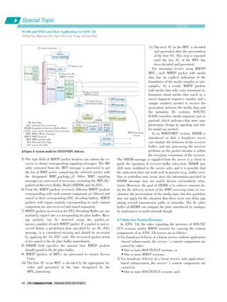
![Time aligned
compressed
media
•Zero or more MMTP sessions.
The use of both MMTP and ROUTE for streaming media
components in the same service is not allowed, and the select⁃
ed protocol is specified in SLT.
3) For broadcast delivery of an application⁃based service, the
content components are carried by:
•One or more ROUTE/LCT sessions.
The combination of sessions with the NRT content can only
be carried by one or more ROUTE/LCT sessions (as described
above). ROUTE/LCT can deliver almost all types of service
components without the assistance of MMTP, but the inverse is
not possible. Using ROUTE/LCT for delivery of service compo⁃
nents appears to be more systematic than MMTP, while the lat⁃
ter is an alternative delivery solution for linear service in
ATSC 3.0.
5 Hybrid Delivery Mode
Hybrid broadcast broadband TV (HbbTV) [26] is a globally
initiative technology mainly developed by industry leaders.
HbbTV aims at improving user experience when it comes to hy⁃
brid content, by harmonizing the broadcast and broadband de⁃
livery through connected TVs, set⁃top boxes and multiscreen
devices. Combining elements of existing standards, including
OIPF, CEA, DVB, MPEG⁃DASH and W3C, HbbTV specifica⁃
tion defines a hybrid (broadcast and broadband) platform for
the signaling, transport and presentation of enhanced or inter⁃
active applications on hybrid terminals, which include both a
DVB compliant broadcast connection and a broadband connec⁃
tion to the Internet. In HbbTV, legacy DVB broadcast stan⁃
dards and systems are furthest maintained, while parts of al⁃
ready available standards based on IP network are largely ref⁃
erenced and adapted where necessary.
In order to integrate all the above technologies organically,
HbbTV specification may need to afford intricate schemes due
to the compatibility of data format, processing procedure and
system architecture. Relatively, the design and development in
ATSC 3.0 system are all based on IP network, and the trans⁃
port protocols in application and physical layers are rede⁃
signed considering new requirements and scenarios. Therefore,
ATSC 3.0 system could provide more systematic and funda⁃
mental solutions to support hybrid delivery of enhanced or in⁃
teractive services.
This section describes hybrid delivery modes. One possible
hybrid delivery operation employs ROUTE/DASH in the broad⁃
cast path and DASH over HTTP(s) in the broadband path. The
other mode uses MMTP/MPU in the broadcast path and DASH
over HTTP(s) in the broadband path.
5.1 Mode with ROUTE/DASH in Broadcast
The hybrid service delivery mode with ROUTE/DASH com⁃
bines the broadcast delivery via ROUTE, and unicast delivery
via HTTP. In some scenarios, e.g., due to device movement,
the broadcast signal may become unavailable, which would re⁃
sult in handover to broadband and may involve a subsequent
return to the broadcast service. Fig. 9 shows the hybrid mode
operation within the DASH client.
The presence of an unmanaged broadband network is likely
to introduce a variable amount of extra delay (latency) in the
delivery, as the network congestion can impact the availability
of the broadband⁃delivered content. ROUTE/DASH allows the
broadcaster to employ techniques specified in the DASH stan⁃
dard to improve user experience in the hybrid delivery case.
Buffering is very important and is handled in a slightly differ⁃
ent way for different delivery modes. DASH segments for uni⁃
cast broadband components are requested by receivers ahead
of when they are needed, as indicated by the timeline set by
the DASH MPD, and they are buffered until their presentation
time. The broadcaster can ensure that broadband⁃delivered ser⁃
vice components are made available to the broadcaster server
well ahead of the broadcast⁃delivered components of the ser⁃
vice to accommodate slower connections.
The receivers control delivery timing and buffering. Seg⁃
ments for broadcast components are delivered from the broad⁃
cast source according to the buffer model, which ensures that
receivers get the segments soon enough to avoid decoder stall
but not so soon as to reduce buffer overflow. The broadcast
source uses the DASH MPD timeline to determine the appro⁃
priate delivery timing.
The possible scenario of switching from broadcast to broad⁃
band service access or vice versa involves the mobile ATSC
3.0 receiver, which due to user mobility, may move temporarily
outside the broadcast coverage and only fallback service recep⁃
tion via broadband is possible. Support for such handover be⁃
tween different access modes may be indicated by the MPD
fragment in SLS. In this case, as defined by the SLS protocols,
the userServiceDescription.deliveryMethod element in the
USBD fragment contains the child elements atsc:broadca⁃
stAppService and atsc:unicastAppService, which represent the
broadcast and broadband delivered components of the named
service. These broadcast and unicast delivered components
may be substituted for one another in the case of handover
from broadcast to broadband service access and vice versa.
Thanks to the uniformity of data encapsulation format in
ROUTE/DASH, the system design and realization adapted for
streaming service with app⁃based enhancement is simple and
systematic, which means that there is few conversion in the me⁃
DASH: Dynamic Adaptive Streaming over HTTP MPD: Media Presentation Description
▲Figure 9. ROUTE/DASH hybrid delivery mode.
Broadcast
Broadcaster
DASH server
Broadband
DASH
client
MPD
and media Codecs
Time aligned
media
presentation
MPD
and media
Special Topic
February 2016 Vol.14 No.1 ZTE COMMUNICATIONSZTE COMMUNICATIONS 47
DASH and MMT and Their Applications in ATSC 3.0
Yiling Xu, Shaowei Xie, Hao Chen, Le Yang, and Jun Sun](https://image.slidesharecdn.com/p020160311277843128165-160314232837/85/Emerging-Technologies-of-Future-Multimedia-Coding-Analysis-and-Transmission-51-320.jpg)
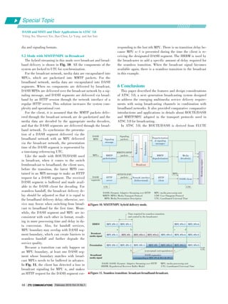
![[27] and DASH, FLUTE is designed for NRT data push servic⁃
es over unidirectional transport and DASH was developed to
realize dynamic adaptive streaming over HTTP. It is the first
time that ROUTE/DASH has been applied to a broadcasting
system. MMTP/MPU was accepted as the MMT standard in
2012. In Japan, super hi⁃vision test services are scheduled to
begin in 2016, and commercial services are scheduled to begin
in 2020 using MMT as a transport protocol for next⁃generation
broadcasting systems.
As developments of ROUTE/DASH and MMT standards, as
well as next generation broadcasting system is still in progress,
further study and verification of technologies adopted in ATSC
3.0 are still needed to be done.
References
[1] 2nd MMT Workshop in Kyoto: Presentations, ISO/IEC JTC 1/SC 29/WG 11
N11200, MPEG, 2010.
[2] P. Podhradsky,“Evolution trends in Hybrid Broadcast Broadband TV”, 55th In⁃
ternational Symposium ELMAR⁃2013, Zadar, Yugoslavia, Sept. 2013.
[3] Information Technology — Generic Coding of Moving Pictures and Associated Au⁃
dio Information: Part 1 Systems, ISO/IEC 13818⁃1, 2013.
[4] Information Technology — Coding of Audio⁃Visual Objects — Part 12 ISO Base
Media File Format, ISO/IEC 14496⁃12, 2012.
[5] Digital Video Broadcasting (DVB), Generic Stream Encapsulation (GSE) Proto⁃
col, ETSI TS 102 606 V1.1.1, Oct. 2007.
[6] R. Pantos and E. W. May. (2011, Oct. 2). HTTP Live Streaming [Online]. Avail⁃
able: http://tools.ietf.org/html/draft⁃pantos⁃http⁃live⁃streaming⁃06
[7] Microsoft. (2009, Sep. 8). IIS Smooth Streaming Transport Protocol [Online].
Available: http://www.iis.net/learn/media/smooth⁃streaming/smooth⁃
⁃streaming⁃transport⁃protocol
[8] Information technology — Dynamic adaptive streaming over HTTP (DASH) —
Part 1: Media presentation description and segment formats. ISO/IEC 23009⁃1,
May 2014.
[9] I. Sodagar,“The MPEG⁃DASH standard for multimedia streaming over the inter⁃
net,”IEEE Multimedia, vol. 18, no. 4, pp. 62- 67, Apr. 2011. doi: 10.1109/
MMUL.2011.71.
[10] ATSC 3.0 Management and Protocols - Signaling, Delivery, Synchronization,
and Error Protection. ATSC Working Draft S33⁃174r0, Dec. 2015.
[11] T. Stoekhammer,“Dynamic adaptive streaming over HTTP⁃design principles
and standards,”in Proc. Second Annual ACM Conference on Multimedia Sys⁃
tems, New York, USA, 2011, pp. 2-4.
[12] C. Müller, S. Lederer, and C. Timmerer,“An evaluation of dynamic adaptive
streaming over HTTP in vehicular environments,”in Proc. 4th Workshop on Mo⁃
bile Video, New York, USA, 2012, pp. 37-42. doi: 10.1145/2151677.2151686.
[13] Information technology — High efficiency coding and media delivery in hetero⁃
geneous environments — Part 1: MPEG media transport (MMT), ISO/IEC 23008
⁃1, 2nd Edition, Jun. 2015.
[14] S. Aoki, K. Otsuki, and H. Hamada,“New media transport technologies in su⁃
per hi⁃vision broadcasting systems,”in Proc. International Broadcasting Con⁃
vention, Amsterdam, Netherlands, Sept. 2013, pp. 7- 9. doi: 10.1049/
ibc.2013.0029.
[15] Y. Lim, K. Park, J. Y. Lee, S. Aoki, and G. Fernando,“MMT: an emerging
MPEG standard for multimedia delivery over the internet,”IEEE Multimedia,
vol. 20, no. 1, pp. 80-85, Mar. 2013. doi: 10.1109/MMUL.2013.7.
[16] S. Aoki, K. Otsuki, and H. Hamada,“Effective usage of MMT in broadcasting
systems,”in IEEE International Symposium on Broadband Multimedia Systems
and Broadcasting, London, UK, Jun. 2013, pp. 1- 6. doi: 10.1109/
BMSB.2013.6621756.
[17] W3C. HTML5: A vocabulary and associated APIs for HTML and XHTML [On⁃
line]. Available: http://www.w3.org/TR/2014/REChtml5⁃20141028/
[18] Layered Coding Transport (LCT) Building Block, IETF: RFC 5651, Oct. 2009.
[19] Hypertext Transfer Protocol ⁃⁃ HTTP/1.1, IETF: RFC 2616, Jun. 1999.
[20] Y. Lim, S. Aoki, I. Bouazizi, and J. Song,“New MPEG transport standard for
next generation hybrid broadcasting system with IP,”IEEE Transactions on
Broadcasting, vol. 60, no. 2, pp. 160- 169, Jun. 2014. doi: 10.1109/
TBC.2014.2315472.
[21] C. Müller, D. Renzi, S. Lederer, et al.,“Using scalable video coding for dynam⁃
ic adaptive streaming over HTTP in mobile environments,”in Proc 20th Euro⁃
pean Signal Processing Conference (EUSIPCO), Bucharest, Romania, Aug.
2012, pp. 2208-2212.
[22] S. Aoki and K. Aoki,“Efficient multiplexing scheme for IP packets over the ad⁃
vanced satellite broadcasting system,”IEEE Transactions on Consumer Elec⁃
tronics., vol. 55, no. 1, pp. 49-55, Feb. 2009. doi: 10.1109/TCE.2009.4814413.
[23] Forward Error Correction (FEC) Framework, IETF: RFC 6363, Oct. 2011.
[24] Joint W3C/IETF URI Planning Interest Group. (2001, Sept. 21). URIs, URLs,
and URNs: Clarifications and Recommendations 1.0 [Online]. Available: https:
//www.w3.org/TR/uri⁃clarification/
[25] W3C. (1997, Sept. 15). Date and Time Formats [Online]. Available: http://www.
w3.org/TR/1998/NOTE⁃datetime⁃19980827
[26] Hybrid Broadcast Broadband TV, ETSI TS 102 796 V1.3.1, Oct. 2015.
[27] FLUTE ⁃ File Delivery over Unidirectional Transport, IETF: RFC 6726, Nov.
2012.
Manuscript received: 2015⁃11⁃15
Yiling Xu (yl.xu@sjtu.edu.cn) received her PhD in electrical engineering from the
University of Electronic Science and Technology of China. From 2004 to 2013, she
was with Multimedia Communication Research Institute of Samsung Electronics
Inc, where she focused on digital broadcasting, IPTV, convergence networks and
next⁃generation multimedia applications. Currently, she is with the Shanghai Jiao⁃
tong University, as a research associate. Dr. Xu has more than 70 patents and 10 ac⁃
ademic papers. She is active in international standard organizations including DVB,
MPEG, 3GPP, OIPF, OMA, and FOBTV.
Shaowei Xie (sw.xie@sjtu.edu.cn) received his BE degree in electronics and infor⁃
mation engineering from Northwestern Polytechnical University, China in 2014. He
is pursuing his PhD degree at the Institute of Image Communication and Signal Pro⁃
cessing, Shanghai Jiao Tong University, China.His research interest is multimedia
communication.
Hao Chen (chenhao1210@sjtu.edu.cn) received his BE degree in electronics and in⁃
formation engineering from Northwestern Polytechnical University, China in 2013.
He is pursuing his PhD degree at the Institute of Image Communication and Signal
Processing, Shanghai Jiao Tong University, China. His research interest is multime⁃
dia communication.
Le Yang (le.yang.le@gmail.com) received his BEng. and MSc degrees in electrical
engineering from the University of Electronic Science and Technology of China, Chi⁃
na in 2000 and 2003, respectively. He received his PhD degree in electrical and
computer engineering from the University of Missouri, USA in 2010. Since 2011, he
has been an associate professor with Jiangnan University, China. His research inter⁃
ests include sensor networks, passive localization, tracking and signal detection.
Jun Sun (junsun@sjtu.edu.cn) received his BS and MS degrees from the University
of Electronic Science and Technology of China in 1989 and 1992, respectively, and
the PhD degree from Shanghai Jiao Tong University, China in 1995. He is a profes⁃
sor with the Institute of Image Communication and Information Processing of Shang⁃
hai Jiao Tong University, China. His research interests include image communica⁃
tion, HDTV, and mobile communication.
BiographiesBiographies
Special Topic
February 2016 Vol.14 No.1 ZTE COMMUNICATIONSZTE COMMUNICATIONS 49
DASH and MMT and Their Applications in ATSC 3.0
Yiling Xu, Shaowei Xie, Hao Chen, Le Yang, and Jun Sun](https://image.slidesharecdn.com/p020160311277843128165-160314232837/85/Emerging-Technologies-of-Future-Multimedia-Coding-Analysis-and-Transmission-53-320.jpg)
![Introduction to AVSIntroduction to AVS22 Scene Video Coding TechniquesScene Video Coding Techniques
Jiaying Yan1,2,3
, Siwei Dong1,3
, Yonghong Tian1,3
, and Tiejun Huang1,3
(1. National Engineering Laboratory for Video Technology, School of EE & CS, Peking University, Beijing 100871, China;
2. School of Electronic and Computer Engineering, Shenzhen Graduate School, Peking University, Shenzhen 518055, China;
3. Cooperative Medianet Innovation Center, Beijing 100871, China)
Abstract
The second generation Audio Video Coding Standard (AVS2) is the most recent video coding standard. By introducing several new
coding techniques, AVS2 can provide more efficient compression for scene videos such as surveillance videos, conference videos,
etc. Due to the limited scenes, scene videos have great redundancy especially in background region. The new scene video coding
techniques applied in AVS2 mainly focus on reducing redundancy in order to achieve higher compression. This paper introduces
several important AVS2 scene video coding techniques. Experimental results show that with scene video coding tools, AVS2 can
save nearly 40% BD⁃rate (Bjøntegaard⁃Delta bit⁃rate) on scene videos.
AVS2; scene videos coding; background prediction
Keywords
DOI: 10.3969/j. issn. 16735188. 2016. 01. 007
http://www.cnki.net/kcms/detail/34.1294.TN.20160122.1015.002.html, published online January 22, 2016
Special Topic
February 2016 Vol.14 No.1ZTE COMMUNICATIONSZTE COMMUNICATIONS50
1 Introduction
he primary application of AVS2 is in ultrahigh⁃def⁃
inition videos, especially scene videos. Scene vid⁃
eos are usually captured by stationary cameras
and include videos from surveillance systems all
over the world and from other applications, such as video con⁃
ference, online teaching and remote medical. Scene videos
have huge temporal and spatial redundancy for the background
regions appear frequently and AVS2 can utilize the back⁃
ground information to compress the scene videos efficiently.
Similar to previous coding standards, AVS2 still adopts the
classic block⁃based hybrid video framework. However, in order
to improve coding efficiency, in the AVS2 coding framework, a
more flexible coding unit (CU), prediction unit (PU) and trans⁃
form unit (TU) based structure is adopted to represent and orga⁃
nize the encoded data. With the quad⁃tree structure, the sizes
of CUs are various from 8×8 to 64×64. At the same time, the
PUs are not limited to symmetric partition while asymmetric
PUs are also available. To make coding more flexible, the size
of TUs is independent from the size of PUs. Moreover, creative
techniques are adopted in AVS2 modules of prediction, trans⁃
form, entropy coding, etc. [1]. Fig. 1 describes the video cod⁃
ing architecture.
The rest of the paper is organized as follows. The related
works are briefly discussed in section 2. Scene video coding
techniques are introduced in section 3. Section 4 contains the
experimental results of AVS2 scene video coding. The paper is
concluded in section 5.
2 Related Works
Some research has been done to improve the compression ef⁃
This work is partially supported by the National Basic Research Program
of China under grant 2015CB351806, the National Natural Science
Foundation of China under contract No. 61425025, No. 61390515 and No.
61421062, and Shenzhen Peacock Plan.
T
GB: background picture
▲Figure 1. The architecture of AVS2 scene video coding.
Background
modelling
GB
picture
Raw video
Transform &
quantization
Entropy
coding
Bitstream
Inv. Transform/
dequantization
Reconstruction
buffer
Loop filter
Reference memory
Background memory
Intra prediction
Inter prediction
Motion
estimation
S picture
decision](https://image.slidesharecdn.com/p020160311277843128165-160314232837/85/Emerging-Technologies-of-Future-Multimedia-Coding-Analysis-and-Transmission-54-320.jpg)
![Introduction to AVS2 Scene Video Coding Techniques
Jiaying Yan, Siwei Dong, Yonghong Tian, and Tiejun Huang
Special Topic
February 2016 Vol.14 No.1 ZTE COMMUNICATIONSZTE COMMUNICATIONS 51
ficiency in scene videos.
One of the most direct solutions for surveillance and confer⁃
ence videos is the object⁃based coding. In the object⁃oriented
analysis⁃synthesis coding method, each video was coded with
motion and shape of objects, color information and prediction
residuals. However, object⁃based coding has three main chal⁃
lenges: accurate foreground segmentation, low⁃cost object rep⁃
resentation, and high⁃efficiency foreground residual coding [2].
In the traditional hybrid coding framework, hybrid block ⁃
based methods are used to encode each picture block by block.
The main types of these methods include the following aspects:
1) Region⁃based coding and 2) Background prediction based
coding. The former aimed at achieving better subjective quali⁃
ty of foreground regions with low coding complexity. Instead,
with the assumption that in scene videos, there might be one
background picture that remains unchanged for a long time,
the second method improves the objective compression effi⁃
ciency by utilizing one background picture as the reference for
the following pictures.
However, there are some regions that may appear in the cur⁃
rent frame but are covered by objects in the recent reference
frames or the key frame. Thus, it is hard to compress the re⁃
gions efficiently by using the key frame as the background. To
address this problem, several background modeling based
methods were proposed, for example, using the reconstructed
pictures to model the background or utilizing the background
picture that was modeled from the original input frames as the
reference for more efficient background prediction.
3 AVS2 Scene Video Coding Techniques
As we know, the key to improve the coding performance effi⁃
ciently of scene videos is reducing the background redundan⁃
cy. AVS2 adopts the long⁃term reference technique and S pic⁃
ture to reduce the background redundancy to improve the cod⁃
ing performance efficiently [3].
3.1 The LongTerm Reference Technique
Traditionally, the current frame can only be inter⁃predicted
by the previous frames in the group of pictures (GOP). Thus,
the distance between the current picture and the reference
frame is only relatively short, which means that the reference
frame may not be able to provide abundant prediction in the
background regions. In order to provide better reference for
background regions, AVS2 adopts a long⁃term reference frame
named background picture (GB picture) [1], [4].
As shown in Fig. 2, GB picture is a background picture
where the whole picture is background regions, so the back⁃
ground regions of each subsequent inter⁃predicted frame can
always find the matching regions in GB picture. When encod⁃
ing the GB picture, only intra mode is utilized, and smaller
Quantization Parameter (QP) is selected to obtain a high quali⁃
ty GB picture. When the P picture is uses the long⁃term refer⁃
ence technique, the reference picture chain comprises general
reference sequence and the long⁃term GB picture. Thus when
the subsequent inter⁃predicted frames choose reference frames
for their background regions, there is high possibility to select
GB picture. Although the GB picture takes a lot of bits, more
bitrate will be saved when the following frames refer GB pic⁃
ture because of the high quality of GB picture. As a result, the
total performance becomes better.
Although the AVS2 standard does not limit the way a GB
picture is generated, it chooses the segment⁃and⁃weight based
running average (SWRA) to generate the GB picture in AVS2
Reference Design (RD). By weighting the frequent values more
heavily in the averaging process, SWRA can generate pure
background. The specific process is as follows. Technological⁃
ly, SWRA divides the pixels at a position in the training pic⁃
tures into temporal segments with their own mean values and
weights and then calculates the running and weighted average
result on the mean values of the segments. In the process, pix⁃
els in the same segment have the same background/foreground
property, and the long segments are more heavily weighted. Ex⁃
perimental results [5] show that SWRA can achieve good per⁃
formance yet without suffering a large memory cost and high
computational complexity, which can meet the requirement of
real⁃time transmission and storage for scene videos. An exam⁃
ple of the constructed background frame and the training
frames are shown in Fig. 3.
Once a GB picture is obtained, it is encoded, and the recon⁃
structed picture is stored in the independent background mem⁃
ory and updated only if a new GB picture is selected or generat⁃
ed. The update mechanism guarantees the effectiveness of the
QPIFrame: the QP value of the I frame
▲Figure 3. The training frames and the background frame.
▲Figure 2. The long⁃term reference technique.
QPIFrame-9
GB-picture
QPIFrame+3 QPIFrame+2 QPIFrame+1
Background
Modeling](https://image.slidesharecdn.com/p020160311277843128165-160314232837/85/Emerging-Technologies-of-Future-Multimedia-Coding-Analysis-and-Transmission-55-320.jpg)
![Special Topic
Introduction to AVS2 Scene Video Coding Techniques
Jiaying Yan, Siwei Dong, Yonghong Tian, and Tiejun Huang
February 2016 Vol.14 No.1ZTE COMMUNICATIONSZTE COMMUNICATIONS52
GB picture.
3.2 S Picture for Random Access
To ensure random access ability, the picture at the random
access point is decoded independent of the previous frames. In
previous coding frame standards, I picture can be used as the
random access point. However, the performance of I picture is
not very well because it only adopts intra prediction and the
performance of intra prediction is not equal to inter prediction.
Along with GB picture and the long⁃term reference technique,
another picture type called S picture is designed for balancing
the coding performance and purpose of random access.
S picture is similar to P picture, which can only be predict⁃
ed from a reconstructed GB picture and has no motion vector,
so only three modes including Intra, Skip and 2N×2N are avail⁃
able in S picture. These characteristics make it possible for an
S picture to be an ideal replacement for an I picture. Before
the S picture is generated, the GB picture if first obtained to
ensure the decoding independence of S picture. Zero motion
vector in the S picture also makes sure that there is no need in
consideration of the motion vector prediction (MVP). Thus the
relative independence of the S picture makes sure it can be set
as the random access point and can present better performance
than I picture.
3.3 Improvement of Motion Vector Derivation
The BlockDistance is the distance between the current
block and the reference block pointed by the motion vector,
which is associated with the picture order count (POC) of refer⁃
ence picture. In the case of one reference with two motion vec⁃
tors, such as F picture, one of the motion vectors is calculated
by the other motion vector. When we introduce GB picture to
AVS2, the problem comes. Because there is no POC existing
in GB picture, the BlockDistance between current block and
its reference block is unavailable if the reference block is from
GB picture. In order to solve the problem, AVS2 provides a
strategy in this situation. If one of the reference pictures is GB
picture, the BlockDistance between current block and the
block in GB picture is restricted to 1. By doing so, the motion
vector derivation is available all the time no matter GB picture
is involved in or not.
4 Performance Evaluation of AVS2 Scene
Video Coding
4.1 Common Test Sequences and Conditions
There are five typical scene videos selected as the common
test sequences [6], [7]. Three are 720×576 surveillance videos,
and the other two are 1600×1200 ones (Table 1). From Fig. 4,
these five surveillance videos cover different monitoring
scenes, including bright and dusky lightness (BR/DU), large
and small foreground (LF/SF), fast and slow motion (FM/SM).
To evaluate the coding performance of the scene video com⁃
pression of AVS2 (RD 12.0.1 Scene), the latest released refer⁃
ence software for AVS2 keeping the scene video coding tech⁃
niques disabled (RD 12.0.1 General) is used as the basic ex⁃
perimental platform. Here, our objective is to evaluate the im⁃
provement in efficiency and reduction in complexity that
AVS2 scene video coding can achieve over AVS2 General.
Four configurations are adopted to perform the experiment
[8]. They are:
1) Low delay (LD);
2) Random Access with B slices (RAB);
3) Random Access with F slices (RAF);
4) Random Access with P slices (RAP).
The F frame is a bidirectional reference frame. Unlike the B
frame, one motion vector of the F frame is derived from the oth⁃
er motion vector.
Table 2 shows the common test conditions of AVS2 scene
video coding.
4.2 Performance Evaluation
The coding performance between RD 12.0.1 Scene and RD
12.0.1 General is shown in Table 3. According to the experi⁃
mental result, RD 12.0.1 Scene reduces 24.33% (LD), 44.11%
(RAB), 40.25% (RAF) and 40.56% (RAP) bitrates in average
against RD 12.0.1 General on 720 × 576 videos and 42.07%
(LD), 39.24% (RAB), 38.36% (RAF) and 37.90% (RAP) on
1600×1200 videos. Among the video sequences, Office and In⁃
tersection have large foreground objects and they are hard to
generate clear background picture, so the coding performance
▼Table 1. The common test sequences of AVS2 scene video coding
Resolution
720×576
1600×1200
FrameRate
30
30
Sequence
Crossroad
Office
Overbridge
Intersection
Mainroad
FramesToBeEncoded
600
600
▲Figure 4. The common test sequences for scene video coding in AVS2.
Office
Mainroad
Overbridge
Intersection
Crossroad](https://image.slidesharecdn.com/p020160311277843128165-160314232837/85/Emerging-Technologies-of-Future-Multimedia-Coding-Analysis-and-Transmission-56-320.jpg)
![February 2016 Vol.14 No.1 ZTE COMMUNICATIONSZTE COMMUNICATIONS 53
is relatively lower than others. In average, RD 12.0.1 Scene
can obtain 31.31% (LD), 42.16% (RAB), 39.49% (RAF) and
39.50% (RAP) bitrate savings on all common test sequences.
5 Conclusions
Based on the classic block⁃based hybrid video framework,
AVS2 is the latest coding standard with efficient scene video
coding techniques and is designed for high efficiency video
coding of scene videos. This paper introduces several represen⁃
tative techniques adopted in AVS2, including the long ⁃ term
reference technique and S picture.
By adopting the techniques of scene video coding mentioned
above, AVS2 can gain 31.31% (LD), 42.16% (RAB), 39.49%
(RAF) and 39.50% (RAP) BD⁃rate saving in coding efficiency
on scene videos. The excellent coding performance of AVS2 in
scene videos coding will bring a bright prospect in video cod⁃
ing research and industrial fields.
Introduction to AVS2 Scene Video Coding Techniques
Jiaying Yan, Siwei Dong, Yonghong Tian, and Tiejun Huang
Special Topic
▼Table 2. The common test conditions of AVS2 scene video coding
References
[1] L. Zhao, S. Dong, P. Xing, and X. Zhang,“AVS2 surveillance video coding plat⁃
form,”AVS M3221, Dec. 2013.
[2] X. Zhang, Y. Tian, T. Huang, S. Dong, and W. Gao,“Optimizing the hierarchical
prediction and coding in hevc for surveillance and conference videos with back⁃
ground modeling,”IEEE Transaction on Image Processing, vol. 23, no.10, pp.
4511-4526, Oct. 2014. doi: 10.1109/TIP.2014.2352036.
[3] F. Liang, “Information technology—advanced media coding part2: video
(FCD4),”AVS N2216, Sept. 2015.
[4] R. Wang, Z. Ren, H. Wang,“Background⁃predictive picture for video coding,”
AVS M2189, Dec. 2007.
[5] X. Zhang, Y. Tian, T. Huang, and W. Gao,“Low⁃complexity and high⁃efficiency
background modelling for surveillance video coding,”in Proc. IEEE Internation⁃
al Conference on Visual Communication and Image Processing, San Diego, USA,
Nov. 2012, pp. 1-6. doi: 10.1109/VCIP.2012.6410796.
[6] S. Dong, L. Zhao,“AVS2 surveillance test sequences,”AVS M3168, Sept. 2013.
[7] L. Yu,“Meeting summary of AVS2 video coding subgroup,”AVS N1998, Sept.
2013.
[8] X. Zheng,“Common test conditions of AVS2 ⁃ P2 surveillance profile,”AVS
N2217, Sept. 2015.
Manuscript received: 2015⁃11⁃25
Jiaying Yan (yanjiaying@pku.edu.cn) received the BS degree from Beijing Institute
of Technology, China in 2014. He is currently pursuing the MS degree with the
School of Electronic and Computer Engineering, Shenzhen Graduate School, Peking
University, China. His research interests include surveillance video coding and mul⁃
timedia learning.
Siwei Dong (swdong@pku.edu.cn) received the B.S. degree from Chongqing Univer⁃
sity, China in 2012. He is currently pursuing the PhD degree with the School of
Electronics Engineering and Computer Science, Peking University, China. His re⁃
search interests include video coding and multimedia learning.
Yonghong Tian (yhtian@pku.edu.cn) is currently a professor with the National Engi⁃
neering Laboratory for Video Technology, School of Electronics Engineering and
Computer Science, Peking University, China. He received the PhD degree from the
Institute of Computing Technology, Chinese Academy of Sciences, China in 2005,
and was also a visiting scientist at Department of Computer Science/Engineering,
University of Minnesota, USA from November 2009 to July 2010. His research inter⁃
ests include machine learning, computer vision, video analysis and coding, and mul⁃
timedia big data. He is the author or coauthor of over 110 technical articles in refer⁃
eed journals and Conferences. Dr. Tian is currently an associate editor of IEEE
Transactions on Multimedia, a young associate editor of the Frontiers of Computer
Science, and a member of the IEEE TCMC⁃TCSEM Joint Executive Committee in
Asia (JECA). He was the recipient of the Second Prize of National Science and Tech⁃
nology Progress Awards in 2010, the best performer in the TRECVID content⁃based
copy detection (CCD) task (2010-2011), the top performer in the TRECVID retro⁃
spective surveillance event detection (SED) task (2009-2012), and the winner of the
WikipediaMM task in ImageCLEF 2008. He is a senior member of IEEE and a
member of ACM.
Tiejun Huang (tjhuang@pku.edu.cn) is a professor with the School of Electronic En⁃
gineering and Computer Science, the chair of Department of Computer Science and
the director of the Institute for Digital Media Technology, Peking University, China.
His research areas include video coding and image understanding, especially neural
coding inspired information coding theory in last years. He received the PhD degree
in pattern recognition and intelligent system from the Huazhong (Central China) Uni⁃
versity of Science and Technology in 1998, and the master’s and bachelor’s de⁃
grees in computer science from the Wuhan University of Technology in 1995 and
1992, respectively. Professor Huang received the National Science Fund for Distin⁃
guished Young Scholars of China in 2014. He is a member of the Board of the Chi⁃
nese Institute of Electronics, the Board of Directors for Digital Media Project and
the Advisory Board of IEEE Computing Now.
BiographiesBiographies
LD: low delay
RAB: random access with B slices
RAF: random access with F slices
RAP: random access with P slices
Parameter
QPIFrame
QPPFrame
QPBFrame
SeqHeaderPeriod
IntraPeriod
NumberBFrames
FrameSkip
BackgroundQP
BackgroundEnable
FFRAMEEnable
ModelNumber
BackgroundPeriod
LD
27, 32, 38, 45
QPIFrame+1
⁃
0
0
0
0
QPIFrame⁃9
1
1
120
900
RAB
QPIFrame+4
1
32
7
7
1
112
RAF
⁃
1
32
0
0
1
900
RAP
⁃
1
32
0
0
0
900
▼Table 3. The coding performance comparison between RD 12.0.1
Scene and RD 12.0.1 General
Resolution
720×576
1600×1200
All
Sequence
Crossroad
Office
Overbridge
Average
Intersection
Mainroad
Average
Average
RD 12.0.1 Scene vs. RD 12.0.1 General (BD⁃Rate)
LD
⁃25.64%
⁃12.66%
⁃34.10%
⁃24.13%
⁃22.46%
⁃61.68%
⁃42.07%
⁃31.31%
RAB
⁃41.99%
⁃26.77%
⁃63.58%
⁃44.11%
⁃22.06%
⁃56.42%
⁃39.24%
⁃42.16%
RAF
⁃37.48%
⁃23.77%
⁃59.50%
⁃40.25%
⁃21.19%
⁃55.52%
⁃38.36%
⁃39.49%
RAP
⁃38.07%
⁃24.10%
⁃59.51%
⁃40.56%
⁃19.91%
⁃55.90%
⁃37.90%
⁃39.50%
BD: Bjøntegaard⁃Delta
RD: Reference Design
LD: low delay
RAB: random access with B slices
RAF: random access with F slices
RAP: random access with P slices](https://image.slidesharecdn.com/p020160311277843128165-160314232837/85/Emerging-Technologies-of-Future-Multimedia-Coding-Analysis-and-Transmission-57-320.jpg)
![From CIA to PDR:From CIA to PDR:
A Top⁃Down Survey of SDNA Top⁃Down Survey of SDN
Security for Cloud DCNSecurity for Cloud DCN
Zhi Liu1, 2
, Xiang Wang1, 2
, and Jun Li1, 3
(1. Research Institute of Information Technology, Tsinghua University,
Beijing 100084, China;
2. Department of Automation, Tsinghua University, Beijing 100084, China;
3. Tsinghua National Laboratory for Information Science and Technology,
Beijing 100084, China)
By extracting the control plane from the data plane, SDN en⁃
ables unprecedented flexibility for future network architec⁃
tures and quickly changes the landscape of the networking
industry. Although the maturity of commonly accepted SDN
security practices is the key to the proliferation of cloud
DCN, SDN security research is still in its infancy. This pa⁃
per gives a top⁃down survey of the approaches in this area,
discussing security challenges and opportunities of software⁃
defined datacenter networking for cloud computing. It lever⁃
ages the well⁃known confidentiality⁃integrity⁃availability (CIA)
matrix and protection⁃detection⁃reaction (PDR) model to give
an overview of current security threats and security mea⁃
sures. It also discusses promising research directions in this
field.
SDN security; cloud DCN; CIA; PDR
DOI: 10.3969/j. issn. 16735188. 2016. 01. 008
http://www.cnki.net/kcms/detail/34.1294.TN.20160118.1527.002.html, published online January 18, 2016
Abstract
Keywords
I
1 Introduction
nformation technology has come a long way — from
mainframes to personal computing and on to mobile
computing. Now we are embracing cloud computing
that was previously called utility computing or grid
computing. In this fascinating transition, datacenters are simi⁃
lar to the mainframes of the old days, and mobile devices are
like the old terminals, only much smarter and not tethered.
Traditional datacenters usually host proprietary services
backed by a number of static and tightly coupled applications.
Traditional datacenter networks (DCNs) mainly deal with large
volumes of north ⁃ south traffic and usually have three layers
(Fig. 1a). The access layer provides the connectivity for serv⁃
ers and storage facilities, normally through top⁃of⁃rack (ToR)
switches. The aggregation layer mediates the access layer to
the core layer, which in turn interfaces to the Internet. As the
cloud evolves towards virtualization and multi⁃tenancy, this ar⁃
chitecture often lacks elasticity and suffers from vendor lock⁃
in [1].
Modern cloud datacenters support a variety of heteroge⁃
neous services for multiple tenants simultaneously. These data⁃
centers are commonly built with a two⁃tier DCN (Fig. 1b). Ten⁃
ants can deploy their own services on the shared infrastructure
and pay⁃as⁃they⁃go. Several software⁃defined datacenter (SD⁃
DC) solutions have been proposed so that capacity can be ex⁃
panded using infrastructure multiplexing and all tenant sys⁃
tems can be managed in an efficient, automatic manner.
Making datacenter services public instead of proprietary sig⁃
nificantly increases infrastructure utilization and drastically af⁃
fects the DCN design. Virtual machines (VMs) are frequently
brought up, shut down, and even migrated across datacenters.
Moreover, VMs of the same tenant may interconnect across
multiple physical servers, and VMs of different tenants may
share the same physical server. These complex scenarios make
it very difficult to guarantee service⁃level agreements (SLAs)
(b) Cloud DCN architecture
▲Figure 1. Evolution of DCN architecture.
(a) Traditional DCN architecture
Security
Core
Aggregation
Access
Fabric
Access
Storage Storage Compute Compute Compute Compute
Storage Storage Compute Compute Compute Security
Review
February 2016 Vol.14 No.1ZTE COMMUNICATIONSZTE COMMUNICATIONS54](https://image.slidesharecdn.com/p020160311277843128165-160314232837/85/Emerging-Technologies-of-Future-Multimedia-Coding-Analysis-and-Transmission-58-320.jpg)
![for each and every tenant.
In the cloud era, novel technologies are required to cope
with emerging DCN security challenges [2]. Such technologies
include topology ⁃ independent service assignment and policy
enforcement, flow ⁃ based (rather than packet ⁃ based) process⁃
ing, and awareness of virtualization and multi⁃tenancy. From
many industrial surveys, we see that security concerns are still
an obstacle to the proliferation of cloud computing [3].
Software⁃defined networking (SDN) is central to addressing
complex network management and security issues. It decou⁃
ples the control plane from the data plane by extracting the
mostly autonomous embedded controllers from traditional net⁃
work elements. The virtually centralized SDN control plane le⁃
verages its global knowledge of network topology and status,
and acts as a network operating system. This enables a network
development and operation (DevOps) team to program network
services via open and standard application programming inter⁃
faces (APIs) such as OpenFlow. This also instigates the rise of
white boxes, as opposed to closed proprietary products of a few
dominant vendors.
Because SDN is not yet mature, cloud DCN security is in its
infancy. Cloud DCN security is a hot research topic and there
is no consensus on it yet. Standardization and industrial appli⁃
cation of cloud DCN security is still at a very early stage. This
paper focuses on the challenges and opportunities related to
cloud DCN. We provide a top⁃down survey of recent approach⁃
es to SDN security and employ the confidentiality ⁃ integrity ⁃
availability (CIA) matrix [4] and protection⁃detection⁃response
(PDR) model [5] for analyzing security threats and measures.
Section 2 reviews related work. Section 3 discusses DCN build⁃
ing blocks and corresponding security demands. Section 4 and
section 5 summarize security threats and security measures, re⁃
spectively. Section 6 concludes the paper.
2 Previous Work
Although SDN and network function virtualization (NFV)
are very recent trends in networking, several comprehensive
surveys of related security research and technologies have al⁃
ready been published [6]- [9]. Some are even updated from
time to time to reflect the fast progress in this area. Existing
surveys have different perspectives on SDN security. Some dis⁃
tinguish between research on protecting the network and re⁃
search on providing security as a service, i.e., secure SDN (se⁃
curity of SDN) and SDN security (security by SDN) [6], [7].
Others analyze and summarize SDN security technologies in
different target environments [8] or according to types of mid⁃
dlebox functions [9].
In [7], the authors review SDN characteristics and present a
survey of security analysis and potential threats in SDN. They
then describe a holistic approach to designing the security ar⁃
chitecture required by SDN. Their summary of the problems
and solutions for each of the main threats to SDN is helpful for
an overall understanding of SDN security advances. The au⁃
thors conclude that, evidenced by the commercially available
applications, work on leveraging SDN to increase network secu⁃
rity is more mature than the solutions addressing the security
issues inherited or introduced by SDN.
In [8], the authors give an overview of existing research on
SDN security, focusing on an analysis of security threats and
potential damage. Such threats include spoofing, tampering, re⁃
pudiation, information disclosure, denial⁃of⁃service (DoS), and
elevation of privilege. The authors also discuss SDN security
measures, such as firewall, intrusion detection system (IDS) (or
intrusion prevention system, IPS), policy management, monitor⁃
ing, auditing, privacy protection, and others controls to threats
in specific networking scenarios. A comprehensive list of refer⁃
ences categorized into different SDN security functionalities is
provided.
This paper takes a more fundamental and focused point of
view from the perspective of practical conditions. We first par⁃
tition the cloud DCN into intra⁃DCN, access⁃DCN, and inter⁃
DCN, and differentiate the unique properties of them. Then,
we analyze the changing attributes of the traditional PDR mod⁃
el from the perspective of CIA matrix.
3 The Three Networks
In a traditional DCN, there are various middleboxes that pro⁃
vide rich network services in addition to basic connectivity of⁃
fered by forwarding devices, such as switches and routers. Fire⁃
walls, IDS/IPS, and other security middleboxes are normally
deployed at the aggregation layer to inspect and steer network
traffic. In this outdated model, policy enforcement is closely
coupled with actual reachability; therefore, the middleboxes
have to sit on the physical packet path, causing administration
difficulties and performance bottlenecks [2].
Leveraging SDN, cloud DCN relies on a flat architecture to
achieve better elasticity and is designed for cost efficiency and
performance enhancement. In this new model, especially in
public cloud DCN with pervasive multi⁃tenancy and high re⁃
source utilization, north ⁃ south traffic gives way to east ⁃ west
traffic [10]. The hierarchical partition of the DCN is no longer
valid, and DCN building blocks can be categorized according
to functional characteristics, such as intra⁃DCN, inter⁃DCN,
and access⁃DCN [10] (Fig. 2).
3.1 IntraDatacenter Network
Intra⁃DCN is the network of resources inside the datacenter.
The intra⁃DCN connects all IT elements together to create
clouds for tenants. With virtualization and multi⁃tenancy, the
clear network boundaries between traditional security zones of
networks usually disappear; thus, network security policies are
now enforced on dynamically distributed network security func⁃
tions [11].
The correctness and efficiency of security policy deployment
Review
From CIA to PDR: A Top⁃Down Survey of SDN Security for Cloud DCN
Zhi Liu, Xiang Wang, and Jun Li
February 2016 Vol.14 No.1 ZTE COMMUNICATIONSZTE COMMUNICATIONS 55](https://image.slidesharecdn.com/p020160311277843128165-160314232837/85/Emerging-Technologies-of-Future-Multimedia-Coding-Analysis-and-Transmission-59-320.jpg)
![depends on the controller’s real⁃time awareness of network to⁃
pology, service status, and traffic pattern. Several approaches
to providing a wide variety of security functionalities for intra⁃
DCN and adapting to network changes have been proposed.
VXLAN [12] and a few other encapsulation protocols are de⁃
ployed for network virtualization to isolate traffic of different
tenants or subnets. Service function chaining (SFC) [13] has
been proposed to orchestrate multiple middleboxes of the same
or different functions. Micro⁃segmentation provides middlebox
functions within L2 networks and delivers fine ⁃ grained net⁃
work security. In OpenStack, the most promising open⁃source
cloud platform, neutron network service program also incu⁃
bates firewall⁃as⁃a⁃service (FWaaS), VPN⁃as⁃a⁃service (VPNa⁃
aS), IDS⁃as⁃a⁃service (IDSaaS), and load⁃balancing⁃as⁃a⁃ser⁃
vice (LBaaS) projects for security service provision within
cloud datacenters.
In existing works on intra⁃DCN security, the focus is on pro⁃
viding security capacity and functions with agility and elastici⁃
ty.
3.2 AccessDatacenter Network
Access ⁃ DCN is the network of clients outside datacenters
that provide direct and pervasive connectivity for users so that
they can access applications running in the cloud.
Distributed denial⁃of⁃service (DDoS) is one of the most hotly
discussed topics related to access interfaces of cloud datacen⁃
ters. There has been some recent advancement on the applica⁃
tion delivery controller (ADC) and web application firewall
(WAF). Other work has also been done on mobile access and
more application⁃specific areas. Existing network security de⁃
vices, such as unified threat management (UTM) and next⁃gen⁃
eration firewall (NGFW), can also provide high performance at
this location, including hardware accelerations.
Because the access points of all tenants are connected to the
Internet, which shares the same IP address space, tenants can
take full advantage of the security hardware resources to com⁃
plete common security inspections. In summary, solutions of
access⁃DCN security mainly focus on optimizing security in⁃
spections.
3.3 InterDatacenter Network
Inter⁃DCN is the network of clouds for federation network⁃
ing between public and private cloud datacenters or optimizing
network resources between multiple datacenter sites.
Google’s B4 [14] is the most influential achievement in inter⁃
datacenter networking. Microsoft’s software⁃driven WAN [15]
is also constructed for peak load shifting. There has not been a
lot of security R&D on this front, mostly because mature virtu⁃
al private network (VPN) technologies already satisfy the basic
security requirements of cloud providers.
The rest of this paper is mainly focused on intra⁃DCN,
which is the focal point of network security and advancement.
4 The Three Threats
Network security threats are becoming more sophisticated
and powerful. Advanced persistent threat (APT) uses blended
hacking schemes to penetrate a network and compromise the
target systems. Recent DDoS attacks have reached 400 Gbps
aggregated network traffic volume, and the number of attacks
over 100 Gbps has greatly increased [16]. Network security
threats all basically boil down to interception, modification, in⁃
terruption, and fabrication. The fundamental security matrix is
still CIA, although authenticity, non⁃repudiation, and other se⁃
curity mechanisms are equally important.
4.1 Threat to Confidentiality
In cloud datacenters, confidentiality may be ensured by ac⁃
cess control list (ACL) and cryptographic solutions. However,
the fundamental challenge lies in tenant isolation. For intra ⁃
DCN, this means tenant traffic isolation: one tenant should not
be able to send or receive network packets to or from another
tenant unless explicitly permitted by the security policy. Ten⁃
ant isolation is a key feature supported by the SDN virtual net⁃
working PaaS.
PortLand [1] is an example of the design and implementa⁃
tion of a non⁃blocking network fabric for virtualized datacen⁃
ters. Multi⁃tenancy and tenant isolation are achieved by chang⁃
ing the processing logic of access switches with the rewriting of
hierarchical pseudo MAC addresses. NetLord [17] proposes an
encapsulation scheme for overlay network virtualization. It can
be deployed on existing networking devices without any modifi⁃
cation and enables different tenants to share the same L2/L3
address spaces. NetLord also has very good scalability.
NVP [18] describes the overall design of network virtualiza⁃
tion platform, including both data plane and control plane. It
leverages Open vSwitch and packet encapsulation to imple⁃
ment the overlay network virtualization, and designs a datalog⁃
DCN: datacenter network VM: virtual machine
▲Figure 2. Three networks of cloud DCN.
VM2
VM1
VM3
Datacenter 1
Intra⁃DCN
Inter⁃DCN
Access⁃DCN
VM2
VM1
VM3
Datacenter 2
VM2
VM1
VM3
Datacenter 3
Tenant 1
Tenant 2
Tenant 3
Desktop Laptop Phone
From CIA to PDR: A Top⁃Down Survey of SDN Security for Cloud DCN
Zhi Liu, Xiang Wang, and Jun Li
Review
February 2016 Vol.14 No.1ZTE COMMUNICATIONSZTE COMMUNICATIONS56](https://image.slidesharecdn.com/p020160311277843128165-160314232837/85/Emerging-Technologies-of-Future-Multimedia-Coding-Analysis-and-Transmission-60-320.jpg)
![based declaration language to define and implement network
policy. LiveCloud [19] further addresses the integration of
hardware networking devices in clouds. It uses both hardware
and software switches to compose the access layer for various
resources.
Reviewing these existing approaches, it can be observed
that traffic is almost always isolated at the network edge, where
the bulk of computing resources can be used for complex pro⁃
cessing logic. At the same time, this requires dynamic policy
coordination and deployment for on ⁃ demand stateful inspec⁃
tion, such as NFV⁃ed firewall, to ensure that policies are glob⁃
ally correct and locally conflict⁃free.
4.2 Threat to Integrity
In terms of integrity in the broader perspective, deep inspec⁃
tion prevents intrusion and/or extrusion and is the most critical
demand [20], including NFV⁃ed IDS/IPS and data leakage pre⁃
vention (DLP).
Player [2] introduces a policy⁃aware switching layer for de⁃
ployment of middleboxes. This approach removes middleboxes
from traffic paths and steers traffic to traverse these devices in
a user⁃defined sequence. It essentially decouples network poli⁃
cies from physical topology, which introduces much more flexi⁃
bility into middlebox deployment. SIMPLE [21] addresses the
same problem but also solves the problems of traffic routing
loops and the negative effects of packet modification. It also
takes into consideration routing and load balancing given
switch constraints. A reliable solution for dynamic middlebox
actions, FlowTags [22] designs a tagging scheme that exposes
the internal mapping of flows before and after middlebox pro⁃
cessing. The introduced tags can be recognized and leveraged
by SDN switches to compose service chains.
On the control plane level, Stratos [23] proposes a frame⁃
work for middlebox orchestration according to workload varia⁃
tion. Tackling the closed middlebox implementation in Stratos,
OpenNF [24] abstracts the middlebox API and designs a series
of APIs for middlebox configuration and notification. These
APIs can be used to coordinate the state control of both middle⁃
boxes and forwarding devices. SDSA [25] introduces a dedicat⁃
ed security controller for security⁃related functionalities, such
as security device management, security policy deployment,
and security event monitoring. The security controller also co⁃
operates with the network controller to obtain a global view
and enforce security policies such as ACL. Considering topolo⁃
gy changes caused by VM migration and dynamic resource re⁃
location, real⁃time security capacity redistribution and policy
instance update are vitally important.
4.3 Threat to Availability
In terms of availability, most security efforts are directed to⁃
wards DoS/DDoS mitigation. To counter attacks and prevent
service unavailability, security middleboxes and policies are of⁃
ten deployed dynamically on these middleboxes. DFence [26]
dynamically instantiates DDoS mitigation middleboxes, inter⁃
cepts suspicious network traffic, and filters attacking traffic. A
dynamic throttling method was also proposed in [27] to prevent
DoS attack. With this method, flows originating from the same
client are limited when the request rate from the client exceeds
a dynamically determined threshold. Pushback [28] has a coop⁃
erative mechanism to mitigate DDoS attacks. The rate of up⁃
stream devices is limited when a DDoS attack occurs so that
the attacking traffic is blocked near its entry point.
Availability security threats have diverse mechanisms for ev⁃
ery specific scenario, which means the identification of suspi⁃
cious traffic patterns (defined by security operators and ex⁃
pressed in the security policy) is very important. Thus, the
management of security policies is central to intra⁃DCN securi⁃
ty. Management of security policies includes policy definition
[29], [30], policy compilation [31], [32], policy assignment
[33], [34], policy optimization [35], [36], policy deployment
[37], [38], and policy lookup [39], [40]. Some research has de⁃
scribed several roadmaps ahead, but so far no consensus has
been reached.
5 The Three Stages
Security is mostly a defensive practice that takes charge of
policy enforcement. From the perspective of control theory, ar⁃
ticulate system design is required to meet application require⁃
ments, where sensors and actuators are versatile for real time
response, and feedback is essential to constantly adapt the situ⁃
ational changes and improve control quality. Many security ap⁃
proaches targeting the SDN⁃based cloud DCN have been pro⁃
posed and can be evaluated in the well⁃known PDR lifecycle
model.
5.1 Protection Stage
In the protection (or planning) stage, the key to intra⁃DCN
security is to design a suitable architecture that both satisfies
the security management requirements and is future⁃proof to a
certain extent.
Unlike traditional DCN, SDN has a global view of the cloud
DCN, and thus enables security mechanisms to be deployed in
a distributed and dynamic manner. Two aspects need to be
weighed in this phase: where to place security functions and
how to manage security policies.
Regarding the placement of security functions, SDN and
NFV devices are orthogonal [41]. Table 1 shows the main dif⁃
ferences between SDN and NFV. SDN focuses on network for⁃
warding, mainly for traffic delivery. It performs stateless pro⁃
cessing of L2⁃L3 network traffic at the packet level according
to network topology. By contrast, the basic responsibility of
NFV is network monitoring, and it is also responsible for secu⁃
rity, measurement, and optimization. NFV conducts stateful
and deep inspection of L4⁃L7 network traffic at the flow level
according to resources and policies.
Review
From CIA to PDR: A Top⁃Down Survey of SDN Security for Cloud DCN
Zhi Liu, Xiang Wang, and Jun Li
February 2016 Vol.14 No.1 ZTE COMMUNICATIONSZTE COMMUNICATIONS 57](https://image.slidesharecdn.com/p020160311277843128165-160314232837/85/Emerging-Technologies-of-Future-Multimedia-Coding-Analysis-and-Transmission-61-320.jpg)
![Conventionally, SDN and NFV devices are managed by dif⁃
ferent administrators. Tualatin [11] is designed according to or⁃
thogonal principles and provides efficient security in a cloud
datacenter. Networking devices and security devices are sepa⁃
rately managed by their corresponding controllers (Fig. 3).
Considering both flexibility and performance, Tualatin decou⁃
ples the security scenarios into intra⁃VN, inter⁃VN, and access⁃
VN and uses hardware and software co⁃design to meet different
security requirements.
There have also been proposals of pushing all middleboxes,
mostly network security functions, to the edge of intra ⁃ DCN
[42] or implementing security inspected in off⁃path control
plane [43]. However, the authors of this paper do not believe
this will solve the problem all together.
Security policies can be enforced with changing [44] or re⁃
specting [33] forwarding policies. Security policy enforcement
combined with forwarding policies can easily introduce perfor⁃
mance impact on the data plane, while security policy enforce⁃
ment based on forwarding policy has clear design boundary
and thus simplifies control plane structure.
5.2 Detection Stage
In the detection (or runtime) stage, network security func⁃
tions are used to discover and defend security attacks.
In Fig. 3, intra⁃VN security depends on traffic statistics gen⁃
erated by NetFlow on software switches to enable heavy⁃load
security inspections. Both ACL and QoS policies are deployed
on software switches. For inter ⁃ VN security, Tualatin chains
multiple security services within a standalone virtual network.
Tualatin introduces a security workload scheduler for load bal⁃
ancing and function composition and exposes fine⁃grain APIs
for flow slice to support micro⁃segmentation. For access⁃VN,
hardware UTM or NGFW can be leveraged for common securi⁃
ty inspections for multiple tenants. This helps with the sharing
of computing resources of security devices.
To efficiently implement these detection engines, virtualized
middleboxes need to be redesigned in a consolidated way.
RouteBricks [45] reveals the curtain of high⁃speed packet pro⁃
cessing on commodity servers. CoMB [46] consolidates middle⁃
box functions and re ⁃ implements them on an X86 platform.
These works demonstrate the possibility of high⁃performance
middleboxes on commodity servers, which lays the foundation
for NFV. OpenGate [47] proposes the architecture for distribut⁃
ed middlebox processing. It takes full advantage of different
hardware platforms to tackle the challenges of L2⁃L3 and L4⁃
L7 processing, which helps to optimize middlebox perfor⁃
mance.
For all these hardware accelerated or software virtualized
functions to cooperate effectively and achieve high perfor⁃
mance, major breakthroughs in policy management technology
is necessary.
5.3 Response Stage
In the response (or feedback) stage, security events, action
results, clues of potential threats, statistical and behavioral
anomalies are collected. The collected information is analyzed
with special tools, including machine learning and big data, to
find new threat signatures or models [48], previously unknown
vulnerabilities [49], and ways to improve security back to the
protection stage. Within industry, security information and
event management (SIEM) advancements can definitely be lev⁃
eraged on this front [50].
6 Conclusion
Modern DCN for cloud computing has made great progress
in terms of architecture evolution, and now SDN and NFV are
leading the way forward. Therefore, SDN security is critical for
▼Table 1. Orthogonality of SDN and NFV
NIC: Network Interface Card AppID: Application Identification
Task
Logical object
Physical object
Basis
State
Manner
Device
Algorithm
Forwarding
Delivery
Packet
L2⁃L3, Header
Topology
Stateless
Local autonomy
NIC, hub, switch, router
Routing origination,
Routing lookup
Monitoring
Security, measurement, optimization
Flow
L2⁃L7, Header + Payload
Resource, policy
Stateful
Global governance
Middlebox
Packet classification, pattern matching,
AppID, traffic management
(b) Operator (physical) view
▲Figure 3. Security service in a cloud datacenter.
(a) Tenant (logical) view
Subnet1
Subnet2
Router
Security policy
Internet
Internet
Host Host
Fabric switch
Network
controller
Security
controller Tenant subnet 1
Tenant subnet 2
Security network
Security workload
scheduler
Edge vSwitch
From CIA to PDR: A Top⁃Down Survey of SDN Security for Cloud DCN
Zhi Liu, Xiang Wang, and Jun Li
Review
February 2016 Vol.14 No.1ZTE COMMUNICATIONSZTE COMMUNICATIONS58
Host Host](https://image.slidesharecdn.com/p020160311277843128165-160314232837/85/Emerging-Technologies-of-Future-Multimedia-Coding-Analysis-and-Transmission-62-320.jpg)
![the proliferation of multifarious cloud services.
Despite the extrinsic nature of various emerging threats—es⁃
pecially those introduced by virtualization and multi⁃tenancy—
the essence of network security is still unchanged. Beginning
with the well⁃known PDR model, this paper has discussed the
latest threats categorized by the CIA matrix as well as network
security advancements.
In the area of intra⁃DCN security, this paper emphasizes the
central role of security policies in the evolution of novel securi⁃
ty mechanisms, including network virtualization and isolation,
intrusion and extrusion prevention, and attack defense and mit⁃
igation. From security architecture to particular algorithms,
from theory to practice, from academia to industry, there have
been more and more proposals and developments around differ⁃
ent aspects of policy management, such as definition, compila⁃
tion, assignment, optimization, deployment and lookup.
Besides the management of security policy, other notable
challenges and opportunities have unveiled promising direc⁃
tions in the green field of DCN security. We argue that there is
yet no sign of framework consensus or approach convergence
in the near future for SDN based cloud DCN security, and we
expect key developments in distributed policy, service chain⁃
ing, as well as visualization and troubleshooting tools.
References
[1] R. N. Mysore, A. Pamboris, N. Farrington, et al.,“PortLand: a scalable fault⁃tol⁃
erant layer 2 data center network fabric,”ACM SIGCOMM Computer Communi⁃
cation Review, vol. 39, no. 4, pp. 39⁃50, 2009. doi: 10.1145/1592568.1592575.
[2] D. A. Joseph, A. Tavakoli, and I. Stoica,“A policy⁃aware switching layer for da⁃
ta centers,”ACM SIGCOMM Computer Communication Review, vol. 38, no. 4,
pp. 51⁃62, 2008. doi: 10.1145/1402958.1402966.
[3] Forbes. Predicting Enterprise Cloud Computing Growth [Online]. Available: http:
//www.forbes.com/sites/louiscolumbus/2013/09/04/predicting ⁃ enterprise ⁃ cloud ⁃
computing⁃growth/
[4] U.S. Government Publishing Office. Public Printing and Documents ⁃ Coordina⁃
tion of Federal Information Policy ⁃ Information Security ⁃ Definitions [Online].
Available: http://www.gpo.gov/fdsys/granule/USCODE ⁃ 2011 ⁃ title44/USCODE ⁃
2011⁃title44⁃chap35⁃subchapIII⁃sec3542/content⁃detail.html
[5] W. Schwartau.“Time based security,”New York, USA: Interpact Press, 1999.
[6] S. T. Ali, V. Sivaraman, A. Radford, and S. Jha,“A survey of securing networks
using software defined networking,”IEEE Transactions on Reliability, vol. 64,
no. 3, pp. 1086⁃1097, Sept. 2015. doi: 10.1109/tr.2015.2421391.
[7] S. Scott⁃Hayward, S. Natarajan, and S. Sezer,“A survey of security in software
defined networks,”IEEE Communications Surveys & Tutorials, vol. PP, no. 99,
p. 1, Jul. 2015. doi: 10.1109/comst.2015.2453114.
[8] I. Alsmadi and D. Xu,“Security of software defined networks: a survey,”Com⁃
puters & Security, vol. 53, pp. 79 ⁃ 108, Sep. 2015. doi: 10.1016/j.
cose.2015.05.006.
[9] J. François, L. Dolberg, O. Festor, and T. Engel,“Network security through soft⁃
ware defined networking: a survey,”in Proc. Conference on Principles, Systems
and Applications of IP Telecommunications, Chicago, USA, 2014, p. 6. doi:
10.1145/2670386.2670390.
[10] Cisco Systems. Cisco Global Cloud Index: Forecast and Methodology, 2014 ⁃
2019 [Online]. Available: http://www.cisco.com/c/en/us/solutions/collateral/ser⁃
vice⁃provider/global⁃cloud⁃index⁃gci/Cloud_Index_White_Paper.html
[11] X. Wang, Z. Liu, B. Yang, Y. Qi, and J. Li,“Tualatin: towards network security
service provision in cloud datacenters,”in IEEE 23rd International Conference
on Computer Communication and Networks (ICCCN), Shanghai, China, 2014,
pp. 1⁃8. doi: 10.1109/icccn.2014.6911782.
[12] Virtual Extensible Local Area Network (VXLAN): A Framework for Overlaying
Virtualized Llayer 2 Networks over Layer 3 Networks, IETF RFC 7348, Aug.
2014.
[13] Service Function Chaining (SFC) Architecture, IETF RFC 7665, Oct. 2015.
[14] S. Jain, A. Kumar, S. Mandal, et al.,“B4: experience with a globally⁃deployed
software defined wan,”ACM SIGCOMM Computer Communication Review, vol.
43, no. 4, pp. 3⁃14, 2013. doi: 10.1145/2486001.2486019.
[15] C. Hong, S. Kandula, R. Mahajan, et al.,“Achieving high utilization with soft⁃
ware ⁃ driven WAN,”ACM SIGCOMM Computer Communication Review, vol.
43, no. 4, pp. 15⁃26, 2013. doi: 10.1145/2486001.2486012.
[16] Akamai. Q2 2015 State of the Internet—Security Report [Online]. Available:
https://www.stateoftheinternet.com/resources⁃cloud⁃security⁃2015⁃q2⁃web⁃se⁃
curity⁃report.html
[17] J. Mudigonda, P. Yalagandula, J. C. Mogul, B. Stiekes, and Y. Pouffary.“Net⁃
Lord: a scalable multi⁃tenant network architecture for virtualized datacenters,”
ACM SIGCOMM Computer Communication Review, vol. 41, no. 4, pp. 62⁃73,
2011. doi: 10.1145/2018436.2018444.
[18] T. Koponen, K. Amidon, P. Balland, et al.,“Network virtualization in multi⁃ten⁃
ant datacenters,”in Proc. 11th USENIX Symposium on Networked Systems De⁃
sign and Implementation, Seattle, USA, Apr. 2014.
[19] X. Wang, Z. Liu, Y. Qi, and J. Li,“LiveCloud: a lucid orchestrator for cloud
datacenters,”in Proc. IEEE 4th International Conference on Cloud Computing
Technology and Science (CloudCom), Los Alamitos, USA, pp. 341⁃348, Dec.
2012. doi: 10.1109/cloudcom.2012.6427544.
[20] A. Bremler⁃Barr, Y. Harchol, D. Hay, and Y. Koral,“Deep packet inspection
as a service,”in Proc. 10th ACM International on Conference on Emerging Net⁃
working Experiments and Technologies, Sydney, Australia, pp. 271⁃282, 2014.
[21] Z. A. Qazi, C. Tu, L. Chiang, et al.,“SIMPLE⁃fying middlebox policy enforce⁃
ment using SDN,”ACM SIGCOMM Computer Communication Review, vol. 43,
no. 4, pp. 27⁃38, 2013. doi: 10.1145/2486001.2486022.
[22] S. Fayazbakhsh, L. Chiang, V. Sekar, M. Yu, and J. Mogul,“Enforcing network⁃
wide policies in the presence of dynamic middlebox actions using FlowTags,”
in Proc. 11th USENIX Symposium on Networked Systems Design and Implemen⁃
tation, Seattle, USA, Apr. 2014, pp. 533⁃546.
[23] A. Gember, A. Krishnamurthy, S. St. John, et al.,“Stratos: a network⁃aware or⁃
chestration layer for middleboxes in the cloud,”University of Wisconsin⁃Madi⁃
son, Madison, USA, Tech. Rep., 2013.
[24] A. Gember, R. Viswanathan, C. Prakash, et al.,“OpenNF: enabling innovation
in network function control,”in Proc. ACM Conference on SIGCOMM, Chicago,
USA, pp. 163⁃174, 2014. doi: 10.1145/2619239.2626313.
[25] W. Liu, X. Qiu, P. Chen, et al.,“SDSA: a programmable software defined secu⁃
rity platform,”in Proc. International Conference on Cloud Computing Research
and Innovation, Biopolis, Singapore, Oct. 2014, pp. 101⁃106.
[26] A. Mahimkar, J. Dange, V. Shmatikov, H. Vin, and Y. Zhang,“dFence: trans⁃
parent network⁃based denial of service mitigation,”Proc. 4th USENIX Sympo⁃
sium on Networked Systems Design and Implementation, Cambridge, USA, Apr.
2007, pp. 327⁃340.
[27] JE Belissent,“Method and apparatus for preventing a denial of service (DoS) at⁃
tack by selectively throttling TCP/IP requests,”U.S. Patent No. 6,789,203. 7,
Sep. 2004.
[28] J. Ioannidis and S. M. Bellovin,“Pushback: router ⁃ based defense against
DDOS attacks,”in Proc. Network and Distributed System Security (NDSS) Sym⁃
posium, San Diego, USA, Feb. 2002. doi: 10.5353/th_b3017330.
[29] T. L. Hinrichs, N. Gude, M. Casado, J. C. Mitchell, and S. Shenker,“Practical
declarative network manage,”in Proc. 1st ACM SIGCOMM Workshop on Re⁃
search on Enterprise Networking, Barcelona, Spain, Aug. 2009, pp. 1⁃10. doi:
10.1007/978⁃3⁃540⁃92995⁃6_5.
[30] C. Prakash, J. Lee, Y. Turner, et al.,“PGA: using graphs to express and auto⁃
matically reconcile network policies,”in Proc. ACM Conference on Special In⁃
terest Group on Data Communication, London, UK, Aug. 2015, pp. 29⁃42. doi:
10.1145/2785956.2787506.
[31] N. Foster, R. Harrison, M. J. Freedman, et al.,“Frenetic: a network program⁃
ming language,”ACM SIGPLAN Notices, vol. 46, no. 9, pp. 279⁃291, 2011. doi:
10.1145/2034773.2034812.
[32] C. Monsanto, J. Reich, N. Foster, J. Rexford, and D. Walker,“Composing soft⁃
ware⁃defined networks,”in Proc. 10th USENIX Symposium on Networked Sys⁃
tems Design and Implementation, Lombard, USA, Apr. 2013. doi: 10.1016/b978
⁃0⁃12⁃416675⁃2.00014⁃0.
[33] N. Kang, Z. Liu, J. Rexford, and D. Walker,“Optimizing the‘one big switch’
abstraction in software⁃defined networks,”in Proc. Ninth ACM Conference on
Emerging Networking Experiments and Technologies, Santa Barbara, USA, Dec.
2013, pp. 13⁃24. doi: 10.1145/2535372.2535373.
[34] X. Wang, W. Shi, Y. Xiang, and J. Li,“Efficient network security policy en⁃
forcement with policy space analysis,”IEEE/ACM Transactions on Networking,
2016. doi: 10.1109/tnet.2015.2502402.
[35] A. R. Curtis, J. C. Mogul, J. Tourrilhes, et al.,“DevoFlow: scaling flow manage⁃
Review
From CIA to PDR: A Top⁃Down Survey of SDN Security for Cloud DCN
Zhi Liu, Xiang Wang, and Jun Li
February 2016 Vol.14 No.1 ZTE COMMUNICATIONSZTE COMMUNICATIONS 59](https://image.slidesharecdn.com/p020160311277843128165-160314232837/85/Emerging-Technologies-of-Future-Multimedia-Coding-Analysis-and-Transmission-63-320.jpg)
![ment for high⁃performance networks,”ACM SIGCOMM Computer Communica⁃
tion Review, vol. 41, no. 4, pp. 254⁃265, 2011. doi: 10.1145/2018436.2018466.
[36] P. Kazemian, G. Varghese, and N. McKeown,“Header space analysis: static
checking for networks,”in Proc. 9th USENIX Symposium on Networked Sys⁃
tems Design and Implementation, San Jose, USA, Apr. 2012, pp. 113⁃126.
[37] M. Reitblatt, N. Foster, J. Rexford, C. Schlesinger, and D. Walker,“Abstrac⁃
tions for network update,”in Proc. ACM SIGCOMM Conference on Applications,
Technologies, Architectures, and Protocols for Computer Communication, Helsin⁃
ki, Finland, Aug. 2012, pp. 323⁃334. doi: 10.1145/2377677.2377748.
[38] W. Zhou, D. Jin, J. Croft, M. Caesar, and P. Godfrey,“Enforcing customizable
consistency properties in software⁃defined networks,”in Proc. 12th USENIX
Symposium on Networked Systems Design and Implementation, Oakland, USA,
Apr. 2015, pp. 73⁃85.
[39] B. Vamanan, G. Voskuilen, and T. Vijaykumar,“EffiCuts: optimizing packet
classification for memory and throughput,”ACM SIGCOMM Computer Commu⁃
nication Review, vol. 41, no. 4, pp. 207 ⁃ 218, 2011. doi: 10.1145/
1851182.1851208.
[40] Y. Qi, L. Xu, B. Yang, Y. Xue, and J. Li,“Packet classification algorithms:
from theory to practice,”in Proc. 28th Conference on Computer Communica⁃
tions, Rio de Janeiro, Brazil, Apr. 2009, pp. 648 ⁃ 656. doi: 10.1109/in⁃
fcom.2009.5061972.
[41] J. McCauley, A. Panda, M. Casado, T. Koponen, and S. Shenker,“Extending
SDN to large⁃scale networks,”Open Networking Summit, Research Track, San⁃
ta Clara, USA, 2013.
[42] S. Ratnasamy and S. Shenker. Quick Overview of SDN/NFV Research at Berke⁃
ley [Online]. Available: http://onrc.stanford.edu/protected% 20files/Day1/6.%
20Overview% 20of% 20SDNv2% 20Architecture% 20and% 20Related% 20Ef⁃
forts.pdf
[43] S. Shin, P. Porras, V. Yegneswaran, et al.,“FRESCO: modular composable se⁃
curity services for software⁃defined networks,”in Proc. 2014 Workshop on Secu⁃
rity of Emerging Networking Technologies, San Diego, USA. doi: 10.14722/
sent.2014.23006.
[44] M. Yu, J. Rexford, M. J. Freedman, and J. Wang.“Scalable flow⁃based network⁃
ing with DIFANE,”ACM SIGCOMM Computer Communication Review, vol. 41,
no. 4, pp. 351⁃362, 2011. doi: 10.1145/1851182.1851224.
[45] M. Dobrescu, N. Egi, K. Argyraki, et al.,“RouteBricks: exploiting parallelism
to scale software routers,”in Proc. ACM SIGOPS 22nd Symposium on Operat⁃
ing Systems Principles, Big Sky, USA, 2009, pp. 15 ⁃ 28. doi: 10.1145/
1629575.1629578.
[46] V. Sekar, N. Egi, S. Ratnasamy, M. Reiter, and G. Shi,“Design and implemen⁃
tation of a consolidated middlebox architecture,”in Proc. 9th USENIX Sympo⁃
sium on Networked Systems Design and Implementation, San Jose, USA, Apr.
2012, pp. 24⁃24.
[47] Y. Qi, F. He, X. Wang, et al.,“OpenGate: towards an open network services
gateway,”Computer Communications, vol. 34, no. 2, pp. 200⁃208, 2011.
[48] M. V. Mahoney and P. K. Chan,“Learning nonstationary models of normal net⁃
work traffic for detecting novel attacks,”in Proc. Eighth ACM SIGKDD Interna⁃
tional Conference on Knowledge Discovery and Data Mining, Edmonton, Cana⁃
da, 2002, pp. 376⁃385. doi: 10.1145/775047.775102.
[49] W. Fan, M. Miller, S. Stolfo, W. Lee, and P. Chan,“Using artificial anomalies
to detect unknown and known network intrusions,”Knowledge and Information
Systems, vol. 6, no. 5, 2004, pp. 507⁃527. doi: 10.1109/icdm.2001.989509.
[50] N. B. Anuar, M. Papadaki, S. Furnell, and N. Clarke,“An investigation and sur⁃
vey of response options for intrusion response systems (IRSs),”in IEEE Infor⁃
mation Security for South Africa, Johannesburg, South Africa, 2010, pp. 1⁃8.
doi: 10.1109/issa.2010.5588654.
Manuscript received: 2015⁃12⁃01
Zhi Liu (zhi⁃liu12@mails.tsinghua.edu.cn) is currently a PhD candidate at Depart⁃
ment of Automation, Tsinghua University, China. He received his BS degree from
Department of Automation, Tsinghua University in 2012. His research interests in⁃
clude software⁃defined networking, cloud datacenter network, and performance opti⁃
mization for networking algorithms and systems.
Xiang Wang (xiang ⁃ wang11@mails.tsinghua.edu.cn) received his PhD degree in
2015 from Department of Automation, Tsinghua University. He received his MS de⁃
gree from the School of Software Engineering, University of Science and Technology
of China in 2010 and BS degree from the School of Telecommunication Engineer⁃
ing, Xidian University, China in 2007. His research interests include software⁃de⁃
fined networking, distributed system, and performance issues in computer network⁃
ing and system architectures.
Jun Li (junl@tsinghua.edu.cn) received his PhD degree in Computer Science from
New Jersey Institute of Technology (NJIT), USA, and MS and BS degrees in Control
and Information from Department of Automation, Tsinghua University. He is cur⁃
rently a professor at Tsinghua University, and Executive Deputy Director of the Tsin⁃
ghua National Laboratory for Information Science and Technology. Before rejoined
Tsinghua University in 2003, he held executive positions at ServGate Technologies,
which he co⁃founded in 1999. Prior to that, he was a senior software engineer at EX⁃
AR and TeraLogic. In between of his MS and PhD studies, he was an assistant pro⁃
fessor then lecturer in the Department of Automation, Tsinghua University. His cur⁃
rent research interests mainly focus on networking and network security.
BiographiesBiographies
From CIA to PDR: A Top⁃Down Survey of SDN Security for Cloud DCN
Zhi Liu, Xiang Wang, and Jun Li
Review
February 2016 Vol.14 No.1ZTE COMMUNICATIONSZTE COMMUNICATIONS60](https://image.slidesharecdn.com/p020160311277843128165-160314232837/85/Emerging-Technologies-of-Future-Multimedia-Coding-Analysis-and-Transmission-64-320.jpg)
![A Software⁃DefinedA Software⁃Defined
Approach to IoTApproach to IoT
NetworkingNetworking
Christian Jacquenet and Mohamed Boucadair
(France Telecom Orange, Cesson⁃Sévigné 35512, France)
It is foreseen that the Internet of Things (IoT) will comprise
billions of connected devices, and this will make the provi⁃
sioning and operation of some IoT connectivity services more
challenging. Indeed, IoT services are very different from lega⁃
cy Internet services because of their dimensioning figures and
also because IoT services differ dramatically in terms of na⁃
ture and constraints. For example, IoT services often rely on
energy and CPU ⁃ constrained sensor technologies, regardless
of whether the service is for home automation, smart building,
e⁃health, or power or water metering on a regional or national
scale. Also, some IoT services, such as dynamic monitoring of
biometric data, manipulation of sensitive information, and pri⁃
vacy needs to be safeguarded whenever this information is for⁃
warded over the underlying IoT network infrastructure. This
paper discusses how software ⁃ defined networking (SDN) can
facilitate the deployment and operation of some advanced IoT
services regardless of their nature or scope. SDN introduces a
high degree of automation in service delivery and operation—
from dynamic IoT service parameter exposure and negotiation
to resource allocation, service fulfillment, and assurance. This
paper does not argue that all IoT services must adopt SDN.
Rather, it is left to the discretion of operators to decide which
IoT services can best leverage SDN capabilities. This paper
only discusses managed IoT services, i.e., services that are op⁃
erated by a service provider.
automation; dynamic service provisioning; Internet of Things;
service function chaining; software⁃defined networking
Abstract
Keywords
DOI: 10.3969/j. issn. 16735188. 2016. 01. 009
http://www.cnki.net/kcms/detail/34.1294.TN.20151116.1025.002.html, published online November 16, 2015
T
1 Introduction
he Internet of Things (IoT) is a highly constrained,
much larger networking infrastructure than legacy
infrastructures that operators have known for de⁃
cades. It is predicted there will be tens of billions
of connected objects in the future, and IoT will be the de facto
networking infrastructure for a plethora of emerging services
[1]. Some of these services are seen by many operators as key
business development opportunities that need to be further ex⁃
plored or industrialized. Some IoT services are being deployed
in the home and in dense urban environments. Other IoT ser⁃
vices, such as e⁃health and energy distribution services, are be⁃
ing deployed on a regional, national or even interplanetary
scale and require large⁃scale networking, computation, and
storage.
IoT connectivity services rely on elementary functions such
as forwarding and routing, quality of service (QoS), and securi⁃
ty.
One of the main differences between IoT connectivity servic⁃
es and legacy connectivity services such as Internet access is
the constrained nature of some of the technologies involved.
For example, a wireless sensor network (WSN) deployed in an
IEEE 802.15.4 [2] network environment assumes a maximum
transmission unit (MTU) of 127 bytes, with only 80 bytes allo⁃
cated to the MAC payload for an average 250 kbps rate.
A WSN includes sensors that are constrained in terms of
CPU and energy. This can affect how IoT service⁃driven poli⁃
cies are designed and enforced, especially when the data being
transported, e.g., personal biometric data, requires a high de⁃
gree of privacy in the forwarding and routing schemes. In addi⁃
tion, IoT dimensioning figures suggest a very different, much
larger networking scale. Several thousand connected devices,
with or without route computation capabilities, are likely to be
the norm rather than the exception in urban and regional areas
and even nationwide (Table 1).
The design and operation of an IoT connectivity service is
complicated by the inherent dynamics of the networking infra⁃
structure. For example, connected devices may be rapidly (re)
grafted onto or pruned from the IoT network infrastructure ac⁃
cording to their CPU loads or remaining energy. They may also
be (re)grafted onto or pruned from the IoT network infrastruc⁃
ture because they are in motion, e.g., biometric sensor brace⁃
lets [3], they have been damaged by weather, or they have en⁃
tered sleep mode.
The deployment of a wide range of IoT services—from
“smart home”residential services and automated building ser⁃
vices to advanced personal e⁃health services—has become a
▼Table 1. What makes IoT routing special
Internet Routing
Nodes are routers
A few hundred nodes
per network
Links and nodes are stable
over time
No stringent routing constraints
Routing is by default not
application⁃aware
IoT Routing
Nodes can be anything—sensors, actuators, routers, etc.
1000+ nodes per network, depending on the nature of
the service
Links are highly unstable and degrade communication.
Nodes fail more often, e.g., exhausted batteries and
CPU overload
Highly constrained environment
Routing must be application⁃aware, e.g., e⁃health ser⁃
vices generate traffic that requires a high degree of pri⁃
vacy whereas energy⁃distribution services generate traf⁃
fic that primarily requires low⁃latency routes
Research Papers
February 2016 Vol.14 No.1 ZTE COMMUNICATIONSZTE COMMUNICATIONS 61](https://image.slidesharecdn.com/p020160311277843128165-160314232837/85/Emerging-Technologies-of-Future-Multimedia-Coding-Analysis-and-Transmission-65-320.jpg)

![tion (e.g., launch a vaccine campaign targeting people at risk).
Moreover, dynamic monitoring of an epidemic requires care⁃
fully designed traffic ⁃ forwarding policies adapted to manage
mobile communities that process emergency calls and collect
statistics on the importance, severity, and scope of the epidem⁃
ic.
These two examples of e⁃health services create network chal⁃
lenges in terms of:
•reliable identification and efficient addressing and naming
schemes for many connected devices (typically health sen⁃
sors)
•dynamic, multimetric, self⁃adaptive route⁃computation
schemes for service performance, scalability and robustness
•privacy preservation, so that sensitive data is not leaked to
illegitimate nodes or data consumers
• dynamic mobility management and self ⁃ adaptive intercon⁃
nected design schemes that leverage existing network infra⁃
structure (both wired and wireless) for the sake of service⁃in⁃
ferred traffic⁃forwarding policies.
Indeed, e⁃health services that dynamically monitor biomet⁃
ric data are available to users who may be mobile. As such,
monitoring traffic⁃forwarding policies should be able to take ad⁃
vantage of available network infrastructures. Network intercon⁃
nects may be needed to forward traffic upstream in the network
or ensure that commands sent by an actuator connected some⁃
where on the Internet are reliably transmitted to the relevant
connected devices. These network interconnects should be
able to accommodate various kinds of IoT traffic envelopes and
ensure such traffic can coexist with other types of traffic in or⁃
der to minimize the risk of service disruption.
Self ⁃ adaptation can then be implemented according to the
nature of the service to be delivered and the subsequent re⁃
source allocation decisions, e.g., route computation and band⁃
width reservation.
2.2 Energy Management and Distribution
Dynamic management of energy distribution is another area
where large⁃scale IoT might be used. Data collected from pow⁃
er meters is forwarded to metro agencies (perhaps for billing)
but also contributes to the management of energy distribution
during peak seasons, such as winter.
Forwarding the corresponding traffic requires capillary and
WSNs that are connected with metropolitan and core networks
(assuming both wired and wireless infrastructures).
Because of the nature of this traffic, adequate traffic engi⁃
neering policies have to be enforced. This ensures that the
computed paths will not only accommodate the type and
amount of available resources but also the typical traffic pat⁃
terns—e.g., N:1 or P:1 group communication schemes as a
function of traffic directionality; sensor⁃collected data forward⁃
ed to metro, regional, or national energy control centers; or
commands generated by an energy⁃control center and forward⁃
ed to a group of sensors so that energy consumption can be bet⁃
ter regulated.
This use case involves additional challenges besides those
already mentioned for the deployment of robust e⁃health servic⁃
es. These challenges are related to:
•designing and dynamically enforcing multicast/broadcast
traffic engineering policies on a large scale
• assessing the effect of corresponding traffic growth on the
performance and scalability of core networking infrastruc⁃
tures from both a design and operation perspective. This re⁃
sults in the development of adapted traffic⁃forwarding para⁃
digms.
•dynamically managing available bandwidth resources, such
as radio channels in 802.15.4e environments.
3 SoftwareDefined Networking Can Help
The nature of some of IoT services encourages operators to
be particularly flexible and agile during the service⁃delivery
and operation phases. Some capabilities, such as firewall, that
are needed to create, deliver, and maintain a feature of an IoT
service may be hosted in various platforms typically located in
a cloud infrastructure. Other capabilities, such as traffic for⁃
warding and QoS, may be supported by in⁃network nodes such
as dedicated service cards or devices with dedicated hardware.
Selection of capabilities needed to dynamically orchestrate
and deliver an IoT service therefore benefits from the flexibili⁃
ty of cloud⁃hosted service platforms and applications coupled
with SDN techniques [4] that include dynamic service⁃inferred
IoT resource allocation and policy enforcement as well as feed⁃
back mechanisms for IoT service fulfillment and assurance.
In recent years, SDN⁃related activities have mostly centered
on how a logically centralized SDN computation logic, often
designated as an SDN controller or orchestrator, can provide
network devices with configuration information pertaining to
the various features required to deliver a (connectivity) service.
Also recently, the application of SDN to IoT networking has
been investigated [5], [6]. However, the focus has primarily
been on dynamically enforcing a traffic⁃forwarding policy with⁃
in an IoT network infrastructure according to abstract models
and virtualized functions.
SDN combined with network function virtualization (NFV)
and mass data analytics is a promising option for introducing
high⁃degree automation into the overall IoT service⁃delivery
procedure (Fig. 1)—from dynamic exposure and negotiation of
IoT service parameters to resource allocation, policy enforce⁃
ment, and service fulfillment and assurance.
Mass data analytics is required to optimize data aggregation
and interpretation. SDN and data analytics can be used togeth⁃
er to react to specific events and observed behaviors of the IoT
underlying infrastructure. For example, they can be used to
propose automated forwarding behaviors when there is an over⁃
load or failure. SDN and data analytics can also be used to
offload some functions from the sensors and mediation servers
A Software⁃Defined Approach to IoT Networking
Christian Jacquenet and Mohamed Boucadair
Research Papers
February 2016 Vol.14 No.1 ZTE COMMUNICATIONSZTE COMMUNICATIONS 63](https://image.slidesharecdn.com/p020160311277843128165-160314232837/85/Emerging-Technologies-of-Future-Multimedia-Coding-Analysis-and-Transmission-67-320.jpg)
![while meeting real⁃time requirements of data processes re⁃
quired by some IoT services. Because time synchronization is
critical for some data retrieval, SDN can be used to synchro⁃
nize the clocks of involved nodes.
With NFV techniques, SDN can instantiate new IoT control⁃
lers and concentrators whenever required and wherever they
are located in the transport network. In this way, data received
from connected devices can be handled appropriately. The lo⁃
cation and dimensioning of these controllers are automatically
fed by SDN intelligence, which is based on various service⁃spe⁃
cific criteria that reflect the business guidelines of the IoT ser⁃
vice provider.
An SDN platform can be used to manage one or more IoT
services. Whether one or several SDN controllers are required
in a given network depends on the deployment strategy, which
has to take into account the number, nature, and scope of the
IoT services to be delivered. Although the application of SDN
techniques to IoT services is attractive, the approach discussed
in this paper does not necessarily benefit each and every IoT
service. Rather, we suggest that a software⁃defined approach to
IoT networking is primarily beneficial for IoT services that re⁃
quire sophisticated treatment and processing.
Sensors are no longer application⁃dependent and can be cus⁃
tomized for an application. SDN can significantly help custom⁃
ize involved nodes at large to accommodate the design require⁃
ments of an IoT service portfolio, from smart home automation
to advanced e⁃health or energy distribution services.
Structurally, IoT services often rely on complex, multifunc⁃
tional network architectures that involve on⁃field hardware
with embedded software, connectivity distributed systems,
cloud software components, and third⁃party developers. Relat⁃
ed challenges include: constrained resources, occasional mas⁃
sive amounts of signaling information, queries, and reduced
computational resources. A typical IoT network of several thou⁃
sand nodes (Table 1) requires new data processing schemes,
stream processing, filtering, aggregation, and data mining.
4 IoTAdapted SDN Mechanics
4.1 Dynamically Exposing and Negotiating IoT Service
Parameters
An IoT connectivity service parameter (standard) template
can be used for the dynamic negotiation procedure between a
customer and IoT service provider [7]. In a biometric data⁃mon⁃
itoring service that typically demands very low latency and pri⁃
vacy⁃preserving routes, such a template would include clauses
about:
•sensor geolocation information, so that the SDN can find the
most suitable routes to the nearest dispatch emergency cen⁃
ter in a reliable and secure manner
•communication schemes and traffic patterns, e.g., a typical
1:N hose model where commands to collect biometric data
during a daily duty cycle can be sent to N sensor bracelets
from a controller in a monitoring center
•QoS guarantees and availability requirements, which may be
expressed in terms of traffic loss or one⁃way delay metrics
•traffic isolation and privacy requirements. This typically re⁃
quires encryption to ensure the privacy of personal data gen⁃
erated by biometric services.
•flow identification information, e.g., the IPv6 source address
used by a given sensor to send data
•any relevant activation means (perhaps to dynamically graft
a sensor to a specific Destination⁃Oriented Directed Acyclic
Graph (DODAG) in a WSN that has Routing Protocol for
Low Power and Lossy Networks (RPL) enabled [8].
4.2 Designing an IoT Service and Dynamically Allocating
Resources
IoT resources can be dynamically selected and allocated ac⁃
cording to the outcomes of the IoT service parameter negotia⁃
tion and according to the information maintained by the SDN
computation logic (Policy Decision Point) in an IoT resource re⁃
pository, which stores the relevant IoT service data models [9].
Notifications originating from the IoT network may also af⁃
fect the decision⁃making process of the SDN computation log⁃
ic. For example, a sensor notifies the SDN computation logic
that a 50% energy threshold has been reached, which leads to
a decision to restrict it to only computing routes that are robust
and reliable.
In the biometric data monitoring example mentioned previ⁃
ously, the outcomes of the service parameter negotiation feed
the SDN computation logic, which derives the Objective Func⁃
tion [10] that locates the nearest grounded root in an RPL net⁃
work environment. This grounded root could be hosted in a
cloud service platform managed by the IoT service provider on
behalf of the emergency dispatch center.
Depending on which RPL metrics best accommodate the IoT
IoT: Internet of Things SDN: software⁃defined networking
▲Figure 1. IoT service delivery procedure.
IoT traffic processing
SDN computation logic (IoT resource allocation, IoT service function
chaining, policy enforcement, etc.)
IoT service structuring layer
IoT service parameter exposure and negotiation
Research Papers
A Software⁃Defined Approach to IoT Networking
Christian Jacquenet and Mohamed Boucadair
February 2016 Vol.14 No.1ZTE COMMUNICATIONSZTE COMMUNICATIONS64](https://image.slidesharecdn.com/p020160311277843128165-160314232837/85/Emerging-Technologies-of-Future-Multimedia-Coding-Analysis-and-Transmission-68-320.jpg)
![service parameter negotiation results, the resulting DODAG to⁃
pology may then look like either a high⁃quality link, battery⁃
free routing environment, or low⁃latency link routing environ⁃
ment.
4.3 Dynamically Structuring IoT Service Function Chains
To differentiate traffic handling in an IoT infrastructure,
SDN ⁃ computed service function chaining techniques may be
used [11]. These techniques are designed to enforce differenti⁃
ated traffic ⁃ forwarding policies within the IoT network infra⁃
structure and satisfy a set of service⁃specific IoT requirements,
such as delegated encryption, security control, traffic shaping
and scheduling, message formatting (add/remove field, version⁃
ing, protocol adjustment), or privacy preservation. In such con⁃
texts, the SDN computation logic dynamically structures the
various service function chains according to service require⁃
ments that need to be satisfied to deliver a specific IoT service.
In the biometric data monitoring example, a set of elementa⁃
ry service functions need to be invoked. Such functions in⁃
clude sleep mode and sensor duty cycle management, to opti⁃
mize energy consumption in particular; encapsulation and
MTU management, to adapt to various network environments
(especially when traffic needs to reach an IoT controller locat⁃
ed upstream in the network); and security management, to pre⁃
serve data privacy.
Fig. 2 shows how two SDN⁃structured IoT service chains—
SFC1 and SFC2—that are applied to traffic that crosses the
IoT SFC domain.
•SFC1 = {Deep Packet Inspection (DPI), 6loWPAN encapsu⁃
lating capability [12], RPL DODAG Information Object
(DIO) trickle timer and Destination Advertisement Object
(DAO) route lifetime settings, TLS Proxy, 6lo decapsulating
capability}
•SFC2 = {DPI, 6lo near field communication (NFC) encapsu⁃
lating capability, expected transmission count (ETX) setting,
auto ACK enforcement, CoAP/HTTP proxy, 6lo decapsulat⁃
ing capability}.
The IoT infrastructure is operated according to policies that
tell IoT devices which flows are to be bound with which service
chain.
4.4 Dynamic Discovery of IoT Resources
An SDN approach involves a bootstrapping procedure for dy⁃
namic discovery of the IoT network topology (including active
nodes), platforms, and their respective capabilities. This is nec⁃
essary to feed the SDN computation logic.
The acquired information is stored and maintained in the re⁃
source repository. IoT service ⁃ driven policy provisioning and
configuration information is derived from this repository and
forwarded to the components that participate in the delivery
and operation of an IoT service.
5 Virtualization Techniques Can Help
Commoditize IoT Devices
The lower layers, up to the Medium Access Control (MAC)
layer, are embedded in commodity hardware. The upper layers,
from the IPv6 network layer to the application layer (where
Constrained Application Protocol (CoAP) [13] and HTTP re⁃
side) are virtualized and controlled by SDN (Fig. 3).
The SDN computation logic dynamically allocates virtual
IPv6 forwarding and other RPL routing instances to master the
flow of CoAP messages sent to a fleet of IoT devices for man⁃
agement purposes.
Such SDN ⁃ based deterministic flow mastery optimizes re⁃
source usage according to various parameters, such as location
of IoT devices, whether these devices are mobile or not; accept⁃
able ETX, to optimize duty cycle management; and data recep⁃
tion rate, to reduce energy consumption.
6 Conclusion and Next Steps
Combining SDN with virtualization is a likely precondition
IoT: Internet of Things SDN: software⁃defined networking SFC: service function chaining
CoAP: Constrained Application Protocol
IoT: Internet of Things
SDN: software⁃defined networking
UDP: User Datagram Protocol
▲Figure 2. SDN⁃computed IoT service function chaining [6]. ▲Figure 3. Virtualized IoT functions [6].
IoT
actuator
IoT
actuator
SFCenabled IoT network domain
SFC1
SFC2 Virtualization
SDN computation logic:
Dynamically structures IoT service functions chains composed of
physical or virtualized service functions
PHY(WiFi, LTE, etc.)
Medium access control
6lo adaptation layer
IPv6
UDP
CoAP/HTTP
Controlfunctions
Application layer
IoT device (e.g., sensor)
Application layer
(Exposes to and negotiates
requirements with SDN controller)
6lo adaptation layer
IPv6
UDP
CoAP/HTTP
virtualized IoT network functions (S/W)
PHY(WiFi, LTE, etc.)
Medium access control
IoT commoditized hardware
IoT SDN controller:
Structures IoT service chains,
allocates serviceand application
derived (virtual) IoT resources
A Software⁃Defined Approach to IoT Networking
Christian Jacquenet and Mohamed Boucadair
Research Papers
February 2016 Vol.14 No.1 ZTE COMMUNICATIONSZTE COMMUNICATIONS 65](https://image.slidesharecdn.com/p020160311277843128165-160314232837/85/Emerging-Technologies-of-Future-Multimedia-Coding-Analysis-and-Transmission-69-320.jpg)
![to the mass adoption of robust, scalable IoT services. IoT ser⁃
vice⁃delivery and operational procedures can leverage SDN—
from service parameter negotiation to resource allocation and
invocation.
Alongside ongoing academic research on SDN in IoT net⁃
working, vendors and operators are developing IoT ⁃ adapted
protocols and data models as well as the computation logic that
lies beneath the SDN intelligence. These are areas where oper⁃
ators can contribute significantly in the years to come.
The SDN approach to IoT networking described in this pa⁃
per is being further assessed through simulation and prototyp⁃
ing. The preliminary results of development activities on multi⁃
metric IoT route computation, cross⁃platform IoT networking,
and IoT⁃specific service function chaining will be communicat⁃
ed in 2016.
References
[1] O. Mazhelis, H. Warma, S. Leminen, et al.,“Internet⁃of⁃things market, value net⁃
works and business models: state⁃of⁃the⁃art report,”University of Jyväskylä,
Jyväskylä, Finland, Tech. Rep. TR⁃39, 2013.
[2] J. T. Adams,“An introduction to IEEE STD 802.15.4,”in IEEE Aerospace Con⁃
ference, Big Sky, MT, USA, 2006. doi: 10.1109/AERO.2006.1655947.
[3] N. Noury, A. Fleury, R. Nocua, et al.,“eHealth sensors, biomedical sensors, al⁃
gorithms and sensor networks,”Innovation and Research in BioMedical Engi⁃
neering, IRBM vol. 30, no. 3, pp. 93-103 , June 2009.
[4] Software⁃Defined Networking: A Perspective from within a Service Provider Envi⁃
ronment, IETF RFC 7149, Mar. 2014.
[5] Z. Qin, G. Denker, C. Gianneli, et al.,“A software defined networking architec⁃
ture for the internet⁃of⁃things,”in IEEE Network Operations and Management
Symposium (NOMS), Krakow, Poland, 2014, pp. 1- 9. doi: 10.1109/
NOMS.2014.6838365.
[6] M.⁃K. Shin, Y. Hong, and C. Y. Ahn,“A software⁃defined approach for end⁃to⁃
end IoT networking,”in Proc. IETF91 SNDRG Working Group Meeting, Honolu⁃
lu, USA, Nov. 2014.
[7] IP Connectivity Provisioning Profile (CPP), IETF RFC 7297, Jul. 2014.
[8] RPL: IPv6 Routing Protocol for Low Power and Lossy Networks, IETF RFC 6550,
Mar. 2012.
[9] R. Sudhaakar and P. Zand,“6tiSCH resource management and interaction using
CoAP,”IETF, draft⁃ietf⁃6tisch⁃coap, Mar. 2015.
[10] Objective Function Zero for the Routing Protocol for Low⁃Power and Lossy Net⁃
works (RPL), IETF RFC 6552, Mar. 2012.
[11] J. Halpern and C. Pignataro,“Service function chaining (SFC) architecture,”
IETF, draft⁃ietf⁃sfc⁃architecture, Aug. 2015.
[12] IETF. IPv6 over Networks of Resource Constrained Nodes (6lo) Working Group
[Online]. Available: https://datatracker.ietf.org/wg/6lo/charter/
[13] The Constrained Application Protocol (CoAP), RFC 7252, Jun. 2014.
Manuscript received: 2015 ⁃10⁃19
Research Papers
A Software⁃Defined Approach to IoT Networking
Christian Jacquenet and Mohamed Boucadair
February 2016 Vol.14 No.1ZTE COMMUNICATIONSZTE COMMUNICATIONS66
Roundup
Introduction to ZTE Communications
ZTE Communications is a quarterly, peer⁃reviewed in⁃
ternational technical journal (ISSN 1673- 5188 and
CODEN ZCTOAK) sponsored by ZTE Corporation, a ma⁃
jor international provider of telecommunications, enter⁃
prise and consumer technology solutions for the Mobile
Internet. The journal publishes original academic papers
and research findings on the whole range of communica⁃
tions topics, including communications and information
system design, optical fiber and electro⁃optical engineer⁃
ing, microwave technology, radio wave propagation, an⁃
tenna engineering, electromagnetics, signal and image
processing, and power engineering. The journal is de⁃
signed to be an integrated forum for university academics
and industry researchers from around the world. ZTE
Communications was founded in 2003 and has a reader⁃
ship of 5500. The English version is distributed to univer⁃
sities, colleges, and research institutes in more than 140
countries.
It is listed in Inspec, Cambridge Scientific Abstracts
(CSA), Index of Copernicus (IC), Ulrich’s Periodicals Di⁃
rectory, Chinese Journal Fulltext Databases, Wanfang Da⁃
ta — Digital Periodicals, and China Science and Technol⁃
ogy Journal Database. Each issue of ZTE Communica⁃
tions is based around a Special Topic, and past issues
have attracted contributions from leading international
experts in their fields.
Christian Jacquenet (christian.jacquenet@orange.com) graduated from the Ecole
Nationale Supérieure de Physique de Marseille, a French school of engineers. He
joined Orange in 1989, and he is currently the director of the Strategic Program Of⁃
fice For Advanced IP Networking, Orange Labs. He is responsible for Orange’s
IPv6 program, which aims to define and drive the the Group’s IPv6 strategy. He al⁃
so conducts development activities in the areas of software⁃defined networking and
service function chaining. He has authored and co⁃authored several Internet drafts
and IETF RFC standards on dynamic routing protocols and resource allocation tech⁃
niques. He has also authored papers and books on IP multicasting, traffic engineer⁃
ing, and automated IP service delivery techniques.
Mohamed Boucadair (mohamed.boucadair@orange.com) is an IP networking strate⁃
gist at France Telecom. He previously worked as a senior IP architect at FT and
worked in the corporate division of FT, which made recommendations on the evolu⁃
tion of IP/MPLS core networks. He has worked for FT R&D and has been part of the
team working on VoIP services. He has been involved in IST research projects,
working on dynamic provisioning and inter⁃domain traffic engineering. He has also
worked as an R&D engineer in charge of dynamic provisioning, QoS, multicast and
intra/inter⁃domain traffic engineering. He has authored many journal articles and
has written extensively on these subjects. He holds several patents on VoIP, IPv4
service continuity, and IPv6.
BiographiesBiographies](https://image.slidesharecdn.com/p020160311277843128165-160314232837/85/Emerging-Technologies-of-Future-Multimedia-Coding-Analysis-and-Transmission-70-320.jpg)


The document is the February 2016 issue of ZTE Communications, focusing on emerging technologies in multimedia coding, analysis, and transmission. It features various research papers on video coding standards and techniques, including the AVS2 standard and high-efficiency video coding (HEVC). Additionally, it announces a call for papers for a special issue on multiple access techniques for 5G networks.