Download to read offline
![International Research Journal of Engineering and Technology (IRJET) e-ISSN: 2395 -0056
Volume: 04 Issue: 02 | Feb -2017 www.irjet.net p-ISSN: 2395-0072
© 2017, IRJET | Impact Factor value: 5.181 | ISO 9001:2008 Certified Journal | Page 1098
REFERENCES:
[1] Triveni Shinde and B. V. Pawar, ―Car anti-collision and
intercommunication system using communication
protocol‖, International journal of engineering sciences
and research technology ISSN:2319-7064,Volume-2, No-6,
pp.187-191, June-2013
[2] S. Saravanan, T. Kavitha, ―Vehicle navigation and
obstacle detection system using RFID and GSM‖, Journal of
Theoretical and Applied Information Technology, Vol.
38,No-2, pp.206-209, 30th April 2012
[3] N. S. Vaidya and A. V .Nikalje, ―Arm based invention in
car mobility and atomization‖, International journal of
engineering and innovative technologyISSN: 2277-3754,
Volume-3, No-5, pp.238-244, november-2013
[4] Vivek agarwal, N. Venkata Murali, and C. Chandramouli,
―A Cost-Effective Ultrasonic Sensor-Based Driver-
Assistance System for Congested Traffic Conditions‖, IEEE
Trans. Intell. Transp. Syst., vol.10, NO.3, pp. 486-498, Sep -
2009
[5] Shival Dubey and Abdul Wahid Ansari, ―Design and
development of vehicle anti-collision system using
electromagnet and ultrasonic sensors‖, International
Journal on Theoretical and Applied Research in Mechanical
Engineering ISSN: 2319 – 3182, Volume-2, No-1, pp.80-83,
Jan-2013
[6] Anusha c, Dr. P. Venkataratnam―Collision Control and
collision avoidance using ultrasonic sensor‖, International
Journal of Current Engineering and Scientific Research
ISSN: 2393-8374, VOLUME-2, ISSUE-7, 2015
[7] Mitchell, W. L. Traffic light control for Emergency
Vehicles, US 4443783, 1984.
[8] Obeck C. J. Traffic signal control for Emergency
Vehicles, US 5014052, 1991.
[9] Rose C. R. et all. Emergency vehicle detection system,
US 5894279, 1999
[10] Shruthi, K R, and K Vinodha. 2012. “Priority based
traffic lights controller.” International journal of
Electronics signals and systems (IJESS) 1(4): 58–61.
[11] Singh, H.K Kumar and H Kaur. 2012. “Intelligent
traffic lights based on RFID.” International Journal of
Computing and Business Research.
[12] Talluri, P, and A Kumar M. 2013. “Intelligent Traffic
system which responds to Emergencies.” International
Journal of Engineering Trends and Technology (IJETT)
4(April): 1132–33.
[13] Vicente Milanes, Jorge Villagra, Jorge Godoy, Javier
Simo, Joshue Perez, and Enrique Onieva, “An Intelligent
V2IBased Traffic Management System”, IEEE Transaction
on Intelligent Transportation System, Vol. 13, No. 1, March
2012.s
[14] Ganesh Khekare, Apeksha Sakhare, “Intelligent Traffic
System for VANET: A Survey”, International Journal of
Advanced Computer Research, Volume-2 Number-4 Issue-
6 Dec 2012.
[15] Sanjay S. Dorle, Pratima L. Patel, “Design Approach
for Dynamic Traffic Control System Based on Radio
Propagation Model in VANET”, International Journal of
Computer Science and Network, Vol 2, Issue 1, 2013.
[16] Ms. Promila Sinhmar, “Intelligent Traffic Light and
Density Control using IR Sensors and Microcontroller”,
International Journal of Advanced Technology &
Engineering Research (IJATER) ISSN No: 2250-3536
VOLUME 2, ISSUE 2, March 2012.
[17] Hosna Tashakkori Hashemi and Siavash Khorsandi,
“Load Balanced VANET Routing in City Environments”,
Vehicular Technology Conference (VTC Spring), 2012
[18] Peyman Babaei, “Vehicles tracking and classification
using traffic zones in a hybrid scheme for intersection
traffic management by smart Road Side Units”, 2010
[19] Kartik Pandit, Ghosal, D., Zhang, H.M., Chen-Nee
Chuah, “Adaptive Traffic Signal Control With Vehicular Ad
hoc Networks”, IEEE Transactions on Vehicular
Technology, Volume: 62 , Issue: 4 May 2013.
[20] Sarika B. Kale, Gajanan P. Dhok, “Design of Intelligent
Ambulance and Traffic Control”, International Journal of
Innovative Technology and Exploring Engineering, ISSN:
2278-3075, Volume-2, Issue-5, 2013.](https://image.slidesharecdn.com/irjet-v4i2213-171118095533/85/Emergency-vehicle-detection-system-using-rf-module-and-ultrasonic-sensor-5-320.jpg)

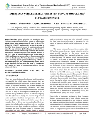
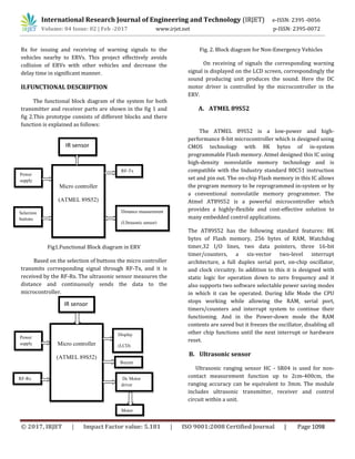
This document describes an emergency vehicle detection system that uses RF modules and ultrasonic sensors to clear lanes and avoid collisions. The system aims to reduce delays and accidents involving emergency response vehicles (ERVs) by controlling nearby vehicles' speeds. When an ultrasonic sensor on an ERV detects an obstacle too close, it sends a control signal to that vehicle's microcontroller to limit its speed. RF transmitters and receivers enable communication between the ERV and other vehicles to issue warning signals and adjust speeds as needed for lane clearance and collision avoidance. The system is intended to provide greater safety for ERVs through intelligent control of nearby traffic.