Intelligent vehicle control using solar powered RFID
•
2 likes•193 views

This document proposes using solar-powered RFID technology to automatically control vehicle speeds based on road signs. An RFID reader in the vehicle detects the speed limit from an active RFID tag attached to a sign. This reference speed and the vehicle's actual speed, measured by a sensor, are inputs to an electronic control unit. The ECU then controls the vehicle's speed through two proposed methods - adjusting the fuel pump to reduce fuel intake, or activating an electro-hydraulic braking system. This system aims to reduce traffic violations by automatically enforcing speed limits without needing infrastructure in rural areas, as the signs are solar powered.

Recommended
Recommended
More Related Content
What's hot
What's hot (20)
Similar to Intelligent vehicle control using solar powered RFID
Similar to Intelligent vehicle control using solar powered RFID (20)
More from eSAT Journals
More from eSAT Journals (20)
Recently uploaded
Recently uploaded (20)
Intelligent vehicle control using solar powered RFID
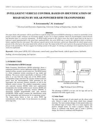
- 1. IJRET: International Journal of Research in Engineering and Technology eISSN: 2319-1163 | pISSN: 2321-7308 __________________________________________________________________________________________ Volume: 03 Issue: 01 | Jan-2014, Available @ http://www.ijret.org 85 INTELLIGENT VEHICLE CONTROL BASED ON IDENTIFICATION OF ROAD SIGNS BY SOLAR POWERED RFID TRANSPONDERS P. Eswaramoorthy1 , M. Arunkumar2 1, 2 Electrical and Electronics Engineering, University College of Engineering, Ariyalur, India Abstract Our paper deals with automatic vehicle speed limit on roads by using solar powered RFID technology to control an automobile. In the present scenario traffic violations are increasing rapidly. It gives rise to major problems which are beyond human control directly and therefore there is a need for automation. An RFID reader present in the vehicle senses the vehicle speed limit on the tag as a reference speed input(attached to the speed limit signboard).Here ,the active RFID tag is used in the signboard which is having a battery supplied from the solar panel. This reference speed is given to the electronic control unit. Meanwhile the vehicle speed sensor present in the wheel gives the actual speed of the vehicle on road. The output of this ECU unit is given to the proposed braking system present in the automobiles. We here suggest two braking systems in this paper. It’s having an advantage of not supplying the power to rural area signboards. Keywords - Solar panel, RFID, ECU (Electronic control unit), speed limit boards, vehicle speed sensor, hydraulic braking, electrical fuel pump, fuel injector. ----------------------------------------------------------------------***------------------------------------------------------------------------ 1. INTRODUCTION 1.1 Introduction to RFID Concept Radio Frequency Identification (RFID) technology shows a continuous growth in various application fields, like logistics, medical science, security, access control etc. The RFID system is a three component system consisting of: tag, reader and database. The access control, specifically, is detection of IDs entry to or exit from the range area of the RFID reader. Transponders (Tags) must have the circuitry needed to harvest power from the electromagnetic fields generated by the interrogator, the necessary memory elements, as well as the different control circuits. The simplest transponders contain only read-only memory (ROM), while more sophisticated transponders also include random access memory (RAM) and nonvolatile programmable read-only memory (PROM) or electrically erasable programmable read- only memory (EEPROM). ROM usually contains the identification string for the transponder and instructions for its operating system . The figure shown below is how an active RFID tag communicates with the reader. In our discussion we consider active tags only. Fig.1 Working of Active RFID tag The advantage of RFID is its low cost for tags and can be attached to the traffic signals easily. 1.2 Solar Panel The most important part of solar panels are the silicon solar cells. Silicon is made of tiny atoms which have charged electrons. The most common design of solar panels today uses two different types of silicon. This is to create negative and positive charged atoms. To create a negative charge, the silicon is combined with Boron, and to create a positive charge, the silicon is combined with Phosphorus.
- 2. IJRET: International Journal of Research in Engineering and Technology eISSN: 2319-1163 | pISSN: 2321-7308 __________________________________________________________________________________________ Volume: 03 Issue: 01 | Jan-2014, Available @ http://www.ijret.org 86 This combination of different solar cells creates more electrons in the positively charged silicon and less electrons in the negatively charged silicon. The positively charged silicon cells are sandwiched with the negatively charged silicon cells. This configuration enables a reaction that produces electricity when the silicon cells are exposed to sunlight. 2. PROPOSED CONCEPT – HOW IT WORKS? The block diagram of the proposed concept is as shown in figure 2 below. It consists of a Solar panel whose energy is stored in the battery and the supply is given to the RFID system which gives the reference speed to the ECU (Electronic control unit). The actual speed of the vehicle is measured using a sensor and is given as another input to ECU. The RFID reader and ECU part resides in the vehicle whereas the RFID tag is connected to either a traffic signal or speed limit signs on roads. The output of the electronic control unit is used to manage the speed of the vehicle. A much detailed explanation of each component is given later in this paper. Fig.2 Block diagram of the proposed system 3. COMPONENTS The selection of panel size, battery and rfid type depends on the required reading range of vehicles. Here we consider upto 30meters of reading range. 3.1 Solar panel For 3.6v rfid, it requires around 16.8v solar panel. Made from a highly efficiency crystalline cell they can provide a continuous trickle feed to any 12 Volt battery which will help to maintain and extend its lifetime. This 5 watt solar panel is also fitted with a blocking diode which prevents reverse current drain. 5 W Solar Panel Kit Specifications and Technical Details High efficiency crystalline cell for “all weather” charging Perfect for battery maintenance and off grid lighting projects Power - 5watts Peak Output - 390mA @ 16.8V Approx. watt-hours/day* - 35 Approx. amp-hours/day* - 2.73 Dimensions - 306 x 218 x 25mm Weight - 1.0kg 3.2 Battery The battery used here are having the capacity of 3.6V,100mA and 4.32Wh.It is often surprising that in most applications, active tags actually have a longer battery life than a semi- passive tag. Although an active tag does require power to transmit, the amount of time that the tag transmits a radio signal is very short. Most of the time (99% or more), the tag is sleeping or taking sensor readings, and not transmitting at all; it is this steady state mode, which actually dominates the battery life of a tag. When the tag does transmit its information, the active tag simply sends its data packet asynchronously and then goes back to sleep; however the semi-passive tag must communicate back and forth with the reader to exchange commands synchronously, which may require the tag to be on for a longer time, even though less power is needed for this function. In addition, an active tag can be programmed to sleep or wake up upon specific events and can asynchronously transmit its information to the reader; as a result, the active tags do not need to be constantly listening for a signal from the reader, which also preserves battery life. Lastly, the modern-day active RFID tag ICs support variable transmission powers, and a tag can lower its transmit power according to the commands from the reader, which further adds to battery life. 3.3 Vehicle Speed Sensor Digi-Pulse speed sensors combine high-sensitivity amplifiers with variable reluctance (VR) or modulated carrier transducers (RF). Unique features include near zero velocity (2 Hz) speed
- 3. IJRET: International Journal of Research in Engineering and Technology eISSN: 2319-1163 | pISSN: 2321-7308 __________________________________________________________________________________________ Volume: 03 Issue: 01 | Jan-2014, Available @ http://www.ijret.org 87 sensing, large air gap capability, and several choices of digital output. By combining the sensor and preamplifier in one unit, reductions in overall cost can be attained especially when preamplifier enclosures and installation labor are considered. Air gap between sensor tip and wheel tooth is used to determine the effectiveness or strength of a signal. The closeness to the wheel determines how effective it is but care should be taken not to damage the sensor. Accuracy will decrease as distance increases. The initial consideration is whether a digital or analog signal is required. The basic variable reluctance (VR) speed sensor provides an analog sine wave. The frequency of the signal will increase as speed increases. If a digital output is desired, options would include amplified versions of VR or RF speed sensors, Hall Effect sensor. Hall Effect sensors are mounted on the front wheels of the vehicle. The output of this sensor is fed into the ECU as original vehicle’s speed. Fig.3 Schematic working of solar powered rfid 3.4 RFID Reader and Transponders RFID reader is placed in the car which detects the tag within the range of 30 meters. The tags placed here contain specific information. The tags which we use here are active tags (turns on only with the power supply). It gets the supply from the solar panel which is placed on each sign boards Tag connected to speed limit boards on the side of the road. These are tags which contain a particular unique code corresponding to the speed on the speed-limit sign boards. This particular reference speed to which the vehicle’s speed has to be reduced to is transmitted by this tag to the RFID reader. The RFID READER (Long Range Reader) using RS- 232 essentially has two connector pins j1 and j2, which are both used as Tx and Rx. The command and data information is available at both the terminals. The RFID READER RS-232 is powered by dc supply via v+ and v-. The information is transmitted or received using an UART or an USART. In this method the data is transmitted in the form of ASCII signals. Moreover, this information is transmitted or received bit by bit sequentially. The transponders used in this are capable of carrying 64 bits of read only data. When a transponder reads a data completely, it will transmit a string of information whose length will vary depending on the type of transponders being scanned. The output format of a transmitted string will be ASCII coded characters. It is followed by $0D which stands for carriage return or end of string marker. 3.5 Electronic Control Unit Electronic control unit manages and monitors the engine functions and performance. The ECU operates in a 3 phase module. In Input phase the ECU gets the information from the various sensors placed in the automobile and continuously monitors the engine’s performance. Next comes the Process phase, after getting inputs the ECU analyses it and on the basis of requirement it takes the operational decisions and the final phase is Output phase, the output phase of an ECU is connected to the driving circuit and in turn this runs the fuel injector. This phase satisfies the desired injection timing . The heart of electronic control unit is its micro controller. The micro controller receives the input and process is based on the program fed onto it. ECU supports CAN interface and/or RS- 232 Interface.
- 4. IJRET: International Journal of Research in Engineering and Technology eISSN: 2319-1163 | pISSN: 2321-7308 __________________________________________________________________________________________ Volume: 03 Issue: 01 | Jan-2014, Available @ http://www.ijret.org 88 4. SPEED CONTROL We suggest two methods as shown below to control the speed of the vehicle. In this case the speed is reduced to the speed limit specified on the roads. 4.1 Electronic Fuel Pump Driving System Control The fuel system provides the injector with the fuel at constant rate and quantity with certain optimum pressure. The ECU we use here controls the timing and quantity of the fuel entering into the injector. The ECU get the input, analyses it and based on the requirement it provides the output. Fig .4 Block Diagram of Electric Fuel Driver System The above setup explains how the electronic fuel pump is controlled by the electronic control unit. After giving the reference and the test input to the ECU, the ECU unit analyses the data according to the micro controller program fed and produces the output. This output is used to control the fuel pump by varying the pulse width. From the fuel pump after passing through the filter it enters the injector which supplies the fuel to the engine. After the reference speed obtained to control the vehicle speed, the ECU will produce an output so as to reduce the pulse width which will delay the fuel pump rate to the injector and so the engine is provided with very less amount of fuel. The function of controlling the motor for the fuel pump can be easily performed by varying time for which the voltage is supplied by the microcontroller in the ECU. 4.2 Electro-Hydraulic Braking System The main advantage of this braking system is that it doesn’t affect the actual braking system provided in the vehicle. This is implemented in the car and only actuated if it comes into the area of the RFID range. During red light situation the RFID reader gives the output to an ECU whose output is connected to this proposed braking system. This hydraulic system is accompanied with electronic components to permit handling of brakes by signals generated by the ECU. The main process before the implementation of the braking system, it is necessary to check the maximum pressure that is exerted by the wheels when manual brakes are applied . This can be found by keeping a bourdon tube in place of the wheels. This is done to make sure that in this autonomous braking system the pressure should not exceed beyond the maximum pressure (say 150 bars). Parts of an electro-hydraulic braking system: • A dc motor pump connected to ECU. • Brake fluid container. • Electro proportional pilot. • Pressure compensator. • Switching valve. • Connection to wheels. This consists of a gear type pump which is coupled with a dc motor and this whole setup is kept inside the brake fluid tank where it is filled with sufficient amount of brake fluid. A pressure limiter or a regulator is used to provide the constant pressure flow rate and also makes sure that is doesn’t cross the maximum limit. If a pressure above the maximum value is given there are chances to damage the original braking system and also it may lead to serious accidents since the driver couldn’t handle the vehicle under this pressure. The main purpose of this regulator is to ensure safety. Regulator is then connected to the electro proportional valve in which a nominal pressure rate can be set. For this system a nominal pressure of 20 to 200 bars can be set. Maximum supply voltage for this valve is 12v. The problem with this electro proportional valve is that it doesn’t have a null pressure even when it is closed. So this minimum amount of pressure is constantly applied to the brakes. So this will cause disturbance for the drivers to drive cars. In order to equalize this residual pressure, a pressure compensator is being used. Another important part of this braking system is the switching valve. Since this braking system doesn’t interfere with the original braking it is to be noted that only one braking system works mainly when a red light situation is considered. This switching valve is a small diameter tube having two inlets, one connecting the original braking and another connecting the automatic braking. Inside this switching valve there is a small ball which can close inlet. This ball moves in the direction opposite to that of the higher pressure side. So that it closes one braking system. The output side of the switching valve is applied to the brake pads on the wheels.
- 5. IJRET: International Journal of Research in Engineering and Technology eISSN: 2319-1163 | pISSN: 2321-7308 __________________________________________________________________________________________ Volume: 03 Issue: 01 | Jan-2014, Available @ http://www.ijret.org 89 Fig.5 Diagram of Electro-Hydraulic Braking System 4.3 Working The batteries placed in the signboards are charged by the solar panel. The charge is given to the active RFID tag which senses the rfid readers around 30 meters. During the vehicle reaches the speed limit zone, the tags are detected by the reader present in the vehicles. Reader produces an output which is again an input to the electronic control unit. On basis of an algorithm, the ECU analyses and produces an output signal. This output is given to the electro proportional pilot. Meanwhile this same output turns on the dc motor, which pumps the braking fluid from the container upwards. The limiter present will set a constant pressure flow and send it to the electro proportional valve. On the basis of the output provided by the ECU, the valve sends only the necessary pressure to be applied on wheels. Say if the output of the ECU is some analog value this analog value is converted to its equivalent pressure value and this pressure is sent to the switching valve. Now since the high pressure will be from the motor side, the ball will close the original braking system. This pressure is applied on the wheels so that the vehicle stops under the red light condition without violating. CONCLUSIONS This paper explains about the solar powered rfid and the automatic brake control of vehicle by the RF transponder identification on speed limiter boards. In the present scenario, due to increase in population, road traffic violations and accidents occur in a large scale. And these violations are highly impossible to control manually, so there is a need for an automatic technology to save human lives. We here propose a reliable method that can be easily placed in the automobiles without affecting the original systems and also the chances of tampering with it are very less. Our approach is mainly based on four steps: giving supply to tags by solar panel,identification of tags, input from vehicle speed sensor to ECU and finally brake control of the vehicle. The communication of the tags (attached to the signals and signboards) with the vehicle, control of automobile ensuring safety was done effectively. Thus this method applied in real- time can revolutionize the traffic management system in an effective manner. REFERENCES [1]. RFID equipped vehicle immobilizer systems including speed control zones and methods relating thereto [2]. Design of RF based speed control system for vehicles - Ankita Mishra, Jyoti Solanki , Harshala Bakshi, Priyanka Saxena, Pranav Paranjpe [3]. Vehicle Speed Limit Alerting and Crash Detection System at Various Zones-D.Narendar Singh [4]. Intelligent Vehicle Control Based on Identification of Road and Traffic Signal Operated RFID transponders