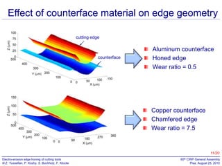
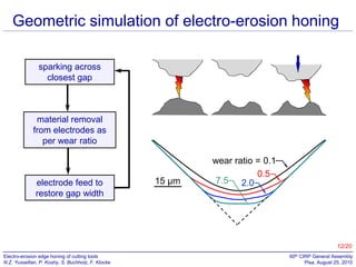
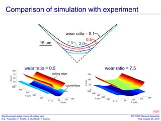
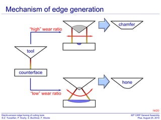
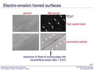
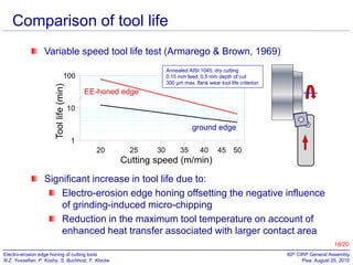
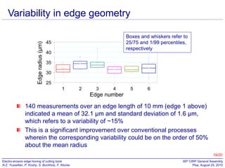
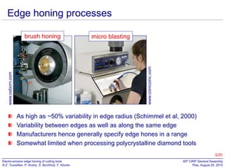
Electro-erosion edge honing
of cutting tools
N. Z. Yussefian, P. Koshy
McMaster University, Canada

S. Buchholz, F. Klocke
RWTH Aachen University, Germany
Edge preparation of cutting tools
~ µm

chip

tool

hone

chamfer

work

Influences chip formation
Affects surface integrity
Precludes catastrophic tool failure
Enhances tool life & coatability
Ensures consistent tool performance

nose radius

X

X

edge radius measured
in X-X plane
2/20
Electro-erosion edge honing of cutting tools
N.Z. Yussefian, P. Koshy, S. Buchholz, F. Klocke

60th CIRP General Assembly
Pisa, August 25, 2010
Influence of edge radius on carbide inserts
An increase in edge radius from 8 µm to 35 µm
Delay in the onset of coating fracture
Four-fold improvement in tool life
Bouzakis et al (2002)

3/20
Electro-erosion edge honing of cutting tools
N.Z. Yussefian, P. Koshy, S. Buchholz, F. Klocke

60th CIRP General Assembly
Pisa, August 25, 2010
Enhancement in high speed steel tool life
Rech et al (2005)

Edge honing enhanced the life of ground tools by ~400%
Existence of an optimal cutting edge radius
4/20
Electro-erosion edge honing of cutting tools
N.Z. Yussefian, P. Koshy, S. Buchholz, F. Klocke

60th CIRP General Assembly
Pisa, August 25, 2010
Edge honing processes
micro blasting

www.osborn.com

www.comcoinc.com

brush honing

As high as ~50% variability in edge radius (Schimmel et al, 2000)
Variability between edges as well as along the same edge
Manufacturers hence generally specify edge hones in a range
Somewhat limited when processing polycrystalline diamond tools
5/20
Electro-erosion edge honing of cutting tools
N.Z. Yussefian, P. Koshy, S. Buchholz, F. Klocke

60th CIRP General Assembly
Pisa, August 25, 2010
Edge rounding in EDM

tool wear in EDM

rounded edges

Possibility of honing cutting edges by sink EDM

sharp

honing

hone

6/20
Electro-erosion edge honing of cutting tools
N.Z. Yussefian, P. Koshy, S. Buchholz, F. Klocke

60th CIRP General Assembly
Pisa, August 25, 2010
Electro-erosion edge honing
Honing of tools by sinking them into an
appropriate counterface
The high level of precision in EDM could
address the variability issue
Tools could be processed irrespective of
material hardness

tool

counterface

The volume of material removal
associated with hone generation is
very minimal
The relatively low material
removal rate of sink EDM is
of little consequence

Conservative EDM parameters may
be employed with a view to
preserving the integrity of the surface
7/20

Electro-erosion edge honing of cutting tools
N.Z. Yussefian, P. Koshy, S. Buchholz, F. Klocke

60th CIRP General Assembly
Pisa, August 25, 2010
Kinematic configurations
feed
symmetric hone
tool
Y
Z

counterface

X

rotation about X axis

rotation of tool about Z axis

asymmetric hone
increasing radius
along the edge
8/20
Electro-erosion edge honing of cutting tools
N.Z. Yussefian, P. Koshy, S. Buchholz, F. Klocke

60th CIRP General Assembly
Pisa, August 25, 2010
Experimental
AISI T-15 High Speed Steel
Aluminum counterface
Finish ground SNEA 320 inserts
10 mm edge length; 90° wedge angle
Dielectric oil; no external flushing

average voltage

80 V

peak current

1.8 A

polarity
pulse on-time

tool (−)
0.6 µs

duty factor

50%

machining time

80 s

Proof of concept & shape evolution
Assessment of tool performance & edge geometry
9/20
Electro-erosion edge honing of cutting tools
N.Z. Yussefian, P. Koshy, S. Buchholz, F. Klocke

60th CIRP General Assembly
Pisa, August 25, 2010
Measurement of edge radius
NURBS model

point cloud data

circular regression
on profile data
150

Knot Points
Edge Cross Section
Fitted Circle

Y [m]

100

50

confocal microscope

0

10/20
Electro-erosion edge honing of cutting tools
N.Z. Yussefian, P. Koshy, S. Buchholz, F. Klocke

-50
100

150

200

250

60th CIRP General Assembly
300Pisa, August 25, 2010
350
400
Effect of counterface material on edge geometry
cutting edge
cutting edge

cutting edge

counterface
counterface

counterface

Aluminum counterface
Honed edge
Wear ratio = 0.5

Copper counterface
Chamfered edge
Wear ratio = 7.5

11/20
Electro-erosion edge honing of cutting tools
N.Z. Yussefian, P. Koshy, S. Buchholz, F. Klocke

60th CIRP General Assembly
Pisa, August 25, 2010
Geometric simulation of electro-erosion honing
sparking across
closest gap

06

54

03

51

0

51-

03-

54-

06-

material removal
from electrodes as
per wear ratio

053
063
073

electrode feed to
restore gap width

15 µm

wear ratio = 0.1
0.5
7.5 2.0

083
093

Fig. 3. Simulated effect of wear ratio on edge geometry.

004

12/20
Electro-erosion edge honing of cutting tools
N.Z. Yussefian, P. Koshy, S. Buchholz, F. Klocke

60th CIRP General Assembly
Pisa, August 25, 2010
Comparison of simulation with experiment
06

54

03

51

0

51-

03-

54-

06053
063

wear ratio = 0.1
0.5
7.5 2.0

073
15 µm

cutting edge

counterface

083
093

Fig. 3. Simulated effect of wear ratio on edge geometry.

004

wear ratio = 0.5

wear ratio = 7.5

cutting edge

counterface

13/20
Electro-erosion edge honing of cutting tools
N.Z. Yussefian, P. Koshy, S. Buchholz, F. Klocke

60th CIRP General Assembly
Pisa, August 25, 2010
Mechanism of edge generation
“high” wear ratio

chamfer

tool

counterface
hone
“low” wear ratio

14/20
Electro-erosion edge honing of cutting tools
N.Z. Yussefian, P. Koshy, S. Buchholz, F. Klocke

60th CIRP General Assembly
Pisa, August 25, 2010
Concept of a threshold wear ratio
counterface

wear ratio = 7.5

tool

A wear ratio much higher than the threshold
results in the generation of a chamfer
A wear ratio much lower than the threshold
results in extensive in-feed of the tool into
the counterface

rβ
feed

β

s

For β = 90°, rβ = 40 µm & s = 15 µm,
threshold wear ratio = 0.4
wear ratio = (Vt /Vc)

counterface
15/20
Electro-erosion edge honing of cutting tools
N.Z. Yussefian, P. Koshy, S. Buchholz, F. Klocke

60th CIRP General Assembly
Pisa, August 25, 2010
Electro-erosion honed surfaces
ground

EE-honed
200 µm

high speed steel

cemented carbide

extensive in-feed of cutting edge into
counterface (wear ratio ~ 0.01)
16/20
Electro-erosion edge honing of cutting tools
N.Z. Yussefian, P. Koshy, S. Buchholz, F. Klocke

60th CIRP General Assembly
Pisa, August 25, 2010
Time evolution of edge geometry

B
unprepared edge
D B
B
-30
Absolute(rβ = 22 µm)
fit circle
30 s Dradial deviation from
F
D
-40
fit circle F ~5% of edge radius
is
60 s (32.6 µm)
H
F
-50
H
10 µm
120
H
120 s (rβ = 40 µm)J sJ(40.3 µm)
-60
ground edge
circle fit (40.3 µm)
N N
J
-70
30 s5. Profilometer tracess (rHSS33 µm) 60
-60
-40
-20
0
N
Fig. (rβ = 22 µm) 60 20 β = 40
of
edges showing their evolution.
-20
0
20
40
60
-20

0

20
40
60
Concept of relative duty (Crookall & Fereday, 1973)

a

a

b

b
a
a

Greater rate of recession
on b-b compared to a-a

work

tool
b

b

17/20
Electro-erosion edge honing of cutting tools
N.Z. Yussefian, P. Koshy, S. Buchholz, F. Klocke

60th CIRP General Assembly
Pisa, August 25, 2010
Comparison of tool life
Variable speed tool life test (Armarego & Brown, 1969)
Annealed AISI 1045; dry cutting
0.15 mm feed; 0.5 mm depth of cut
300 µm max. flank wear tool life criterion

Tool life (min)

100

EE-honed edge
10

ground edge
1
20

25

30

35

40

45

50

Cutting speed (m/min)

Significant increase in tool life due to:
Electro-erosion edge honing offsetting the negative influence
of grinding-induced micro-chipping
Reduction in the maximum tool temperature on account of
enhanced heat transfer associated with larger contact area
18/20
Electro-erosion edge honing of cutting tools
N.Z. Yussefian, P. Koshy, S. Buchholz, F. Klocke

60th CIRP General Assembly
Pisa, August 25, 2010
Edge radius (µm)

Variability in edge geometry
Boxes and whiskers refer to
25/75 and 1/99 percentiles,
respectively

45
40
35
30
25
1

2

3

4

5

6

Edge number

140 measurements over an edge length of 10 mm (edge 1 above)
indicated a mean of 32.1 µm and standard deviation of 1.6 µm,
which refers to a variability of ~15%
This is a significant improvement over conventional processes
wherein the corresponding variability could be on the order of 50%
about the mean radius
19/20
Electro-erosion edge honing of cutting tools
N.Z. Yussefian, P. Koshy, S. Buchholz, F. Klocke

60th CIRP General Assembly
Pisa, August 25, 2010
Conclusions
The application of electrical spark discharges
for edge honing has been demonstrated
The counterface material plays a critical role
in the geometry of the generated edge
Edge hones generated by electro-erosion
honing significantly improved the life of
ground tools
Electro-erosion honing corresponds to robust
edge geometry generation as compared to
conventional processes
20/20
Electro-erosion edge honing of cutting tools
N.Z. Yussefian, P. Koshy, S. Buchholz, F. Klocke

60th CIRP General Assembly
Pisa, August 25, 2010
Canadian Network of Centers of Excellence

Thank you
for your
kind attention!

C4 Consortium of Ontario

Electro-erosion edge honing of cutting tools
N.Z. Yussefian, P. Koshy, S. Buchholz, F. Klocke

60th CIRP General Assembly
Pisa, August 25, 2010

Electro Erosion Edge Honing

  • 1.
    Electro-erosion edge honing ofcutting tools N. Z. Yussefian, P. Koshy McMaster University, Canada S. Buchholz, F. Klocke RWTH Aachen University, Germany
  • 2.
    Edge preparation ofcutting tools ~ µm chip tool hone chamfer work Influences chip formation Affects surface integrity Precludes catastrophic tool failure Enhances tool life & coatability Ensures consistent tool performance nose radius X X edge radius measured in X-X plane 2/20 Electro-erosion edge honing of cutting tools N.Z. Yussefian, P. Koshy, S. Buchholz, F. Klocke 60th CIRP General Assembly Pisa, August 25, 2010
  • 3.
    Influence of edgeradius on carbide inserts An increase in edge radius from 8 µm to 35 µm Delay in the onset of coating fracture Four-fold improvement in tool life Bouzakis et al (2002) 3/20 Electro-erosion edge honing of cutting tools N.Z. Yussefian, P. Koshy, S. Buchholz, F. Klocke 60th CIRP General Assembly Pisa, August 25, 2010
  • 4.
    Enhancement in highspeed steel tool life Rech et al (2005) Edge honing enhanced the life of ground tools by ~400% Existence of an optimal cutting edge radius 4/20 Electro-erosion edge honing of cutting tools N.Z. Yussefian, P. Koshy, S. Buchholz, F. Klocke 60th CIRP General Assembly Pisa, August 25, 2010
  • 5.
    Edge honing processes microblasting www.osborn.com www.comcoinc.com brush honing As high as ~50% variability in edge radius (Schimmel et al, 2000) Variability between edges as well as along the same edge Manufacturers hence generally specify edge hones in a range Somewhat limited when processing polycrystalline diamond tools 5/20 Electro-erosion edge honing of cutting tools N.Z. Yussefian, P. Koshy, S. Buchholz, F. Klocke 60th CIRP General Assembly Pisa, August 25, 2010
  • 6.
    Edge rounding inEDM tool wear in EDM rounded edges Possibility of honing cutting edges by sink EDM sharp honing hone 6/20 Electro-erosion edge honing of cutting tools N.Z. Yussefian, P. Koshy, S. Buchholz, F. Klocke 60th CIRP General Assembly Pisa, August 25, 2010
  • 7.
    Electro-erosion edge honing Honingof tools by sinking them into an appropriate counterface The high level of precision in EDM could address the variability issue Tools could be processed irrespective of material hardness tool counterface The volume of material removal associated with hone generation is very minimal The relatively low material removal rate of sink EDM is of little consequence Conservative EDM parameters may be employed with a view to preserving the integrity of the surface 7/20 Electro-erosion edge honing of cutting tools N.Z. Yussefian, P. Koshy, S. Buchholz, F. Klocke 60th CIRP General Assembly Pisa, August 25, 2010
  • 8.
    Kinematic configurations feed symmetric hone tool Y Z counterface X rotationabout X axis rotation of tool about Z axis asymmetric hone increasing radius along the edge 8/20 Electro-erosion edge honing of cutting tools N.Z. Yussefian, P. Koshy, S. Buchholz, F. Klocke 60th CIRP General Assembly Pisa, August 25, 2010
  • 9.
    Experimental AISI T-15 HighSpeed Steel Aluminum counterface Finish ground SNEA 320 inserts 10 mm edge length; 90° wedge angle Dielectric oil; no external flushing average voltage 80 V peak current 1.8 A polarity pulse on-time tool (−) 0.6 µs duty factor 50% machining time 80 s Proof of concept & shape evolution Assessment of tool performance & edge geometry 9/20 Electro-erosion edge honing of cutting tools N.Z. Yussefian, P. Koshy, S. Buchholz, F. Klocke 60th CIRP General Assembly Pisa, August 25, 2010
  • 10.
    Measurement of edgeradius NURBS model point cloud data circular regression on profile data 150 Knot Points Edge Cross Section Fitted Circle Y [m] 100 50 confocal microscope 0 10/20 Electro-erosion edge honing of cutting tools N.Z. Yussefian, P. Koshy, S. Buchholz, F. Klocke -50 100 150 200 250 60th CIRP General Assembly 300Pisa, August 25, 2010 350 400
  • 11.
    Effect of counterfacematerial on edge geometry cutting edge cutting edge cutting edge counterface counterface counterface Aluminum counterface Honed edge Wear ratio = 0.5 Copper counterface Chamfered edge Wear ratio = 7.5 11/20 Electro-erosion edge honing of cutting tools N.Z. Yussefian, P. Koshy, S. Buchholz, F. Klocke 60th CIRP General Assembly Pisa, August 25, 2010
  • 12.
    Geometric simulation ofelectro-erosion honing sparking across closest gap 06 54 03 51 0 51- 03- 54- 06- material removal from electrodes as per wear ratio 053 063 073 electrode feed to restore gap width 15 µm wear ratio = 0.1 0.5 7.5 2.0 083 093 Fig. 3. Simulated effect of wear ratio on edge geometry. 004 12/20 Electro-erosion edge honing of cutting tools N.Z. Yussefian, P. Koshy, S. Buchholz, F. Klocke 60th CIRP General Assembly Pisa, August 25, 2010
  • 13.
    Comparison of simulationwith experiment 06 54 03 51 0 51- 03- 54- 06053 063 wear ratio = 0.1 0.5 7.5 2.0 073 15 µm cutting edge counterface 083 093 Fig. 3. Simulated effect of wear ratio on edge geometry. 004 wear ratio = 0.5 wear ratio = 7.5 cutting edge counterface 13/20 Electro-erosion edge honing of cutting tools N.Z. Yussefian, P. Koshy, S. Buchholz, F. Klocke 60th CIRP General Assembly Pisa, August 25, 2010
  • 14.
    Mechanism of edgegeneration “high” wear ratio chamfer tool counterface hone “low” wear ratio 14/20 Electro-erosion edge honing of cutting tools N.Z. Yussefian, P. Koshy, S. Buchholz, F. Klocke 60th CIRP General Assembly Pisa, August 25, 2010
  • 15.
    Concept of athreshold wear ratio counterface wear ratio = 7.5 tool A wear ratio much higher than the threshold results in the generation of a chamfer A wear ratio much lower than the threshold results in extensive in-feed of the tool into the counterface rβ feed β s For β = 90°, rβ = 40 µm & s = 15 µm, threshold wear ratio = 0.4 wear ratio = (Vt /Vc) counterface 15/20 Electro-erosion edge honing of cutting tools N.Z. Yussefian, P. Koshy, S. Buchholz, F. Klocke 60th CIRP General Assembly Pisa, August 25, 2010
  • 16.
    Electro-erosion honed surfaces ground EE-honed 200µm high speed steel cemented carbide extensive in-feed of cutting edge into counterface (wear ratio ~ 0.01) 16/20 Electro-erosion edge honing of cutting tools N.Z. Yussefian, P. Koshy, S. Buchholz, F. Klocke 60th CIRP General Assembly Pisa, August 25, 2010
  • 17.
    Time evolution ofedge geometry B unprepared edge D B B -30 Absolute(rβ = 22 µm) fit circle 30 s Dradial deviation from F D -40 fit circle F ~5% of edge radius is 60 s (32.6 µm) H F -50 H 10 µm 120 H 120 s (rβ = 40 µm)J sJ(40.3 µm) -60 ground edge circle fit (40.3 µm) N N J -70 30 s5. Profilometer tracess (rHSS33 µm) 60 -60 -40 -20 0 N Fig. (rβ = 22 µm) 60 20 β = 40 of edges showing their evolution. -20 0 20 40 60 -20 0 20 40 60 Concept of relative duty (Crookall & Fereday, 1973) a a b b a a Greater rate of recession on b-b compared to a-a work tool b b 17/20 Electro-erosion edge honing of cutting tools N.Z. Yussefian, P. Koshy, S. Buchholz, F. Klocke 60th CIRP General Assembly Pisa, August 25, 2010
  • 18.
    Comparison of toollife Variable speed tool life test (Armarego & Brown, 1969) Annealed AISI 1045; dry cutting 0.15 mm feed; 0.5 mm depth of cut 300 µm max. flank wear tool life criterion Tool life (min) 100 EE-honed edge 10 ground edge 1 20 25 30 35 40 45 50 Cutting speed (m/min) Significant increase in tool life due to: Electro-erosion edge honing offsetting the negative influence of grinding-induced micro-chipping Reduction in the maximum tool temperature on account of enhanced heat transfer associated with larger contact area 18/20 Electro-erosion edge honing of cutting tools N.Z. Yussefian, P. Koshy, S. Buchholz, F. Klocke 60th CIRP General Assembly Pisa, August 25, 2010
  • 19.
    Edge radius (µm) Variabilityin edge geometry Boxes and whiskers refer to 25/75 and 1/99 percentiles, respectively 45 40 35 30 25 1 2 3 4 5 6 Edge number 140 measurements over an edge length of 10 mm (edge 1 above) indicated a mean of 32.1 µm and standard deviation of 1.6 µm, which refers to a variability of ~15% This is a significant improvement over conventional processes wherein the corresponding variability could be on the order of 50% about the mean radius 19/20 Electro-erosion edge honing of cutting tools N.Z. Yussefian, P. Koshy, S. Buchholz, F. Klocke 60th CIRP General Assembly Pisa, August 25, 2010
  • 20.
    Conclusions The application ofelectrical spark discharges for edge honing has been demonstrated The counterface material plays a critical role in the geometry of the generated edge Edge hones generated by electro-erosion honing significantly improved the life of ground tools Electro-erosion honing corresponds to robust edge geometry generation as compared to conventional processes 20/20 Electro-erosion edge honing of cutting tools N.Z. Yussefian, P. Koshy, S. Buchholz, F. Klocke 60th CIRP General Assembly Pisa, August 25, 2010
  • 21.
    Canadian Network ofCenters of Excellence Thank you for your kind attention! C4 Consortium of Ontario Electro-erosion edge honing of cutting tools N.Z. Yussefian, P. Koshy, S. Buchholz, F. Klocke 60th CIRP General Assembly Pisa, August 25, 2010