This document presents an online efficiency optimization method for an interior permanent magnet synchronous motor (IPMSM) drive system in an electric vehicle. A finite element analysis is used to build an accurate machine model that considers magnetic saturation, spatial harmonics, and iron loss effects. The proposed method calculates the total system losses, including fundamental copper and iron losses, harmonic copper and iron losses, magnet loss, and inverter losses. An online algorithm is developed to determine the optimal current angle for maximum efficiency per ampere control over the entire speed range. Simulation results demonstrate the superior performance of the proposed online method over conventional offline efficiency optimization techniques.
![International Journal of Power Electronics and Drive Systems (IJPEDS)
Vol. 12, No. 3, September 2021, pp. 1369~1378
ISSN: 2088-8694, DOI: 10.11591/ijpeds.v12.i3.pp1369-1378 1369
Journal homepage: http://ijpeds.iaescore.com
Online efficiency optimization of IPMSM for electric vehicles
Hanaa Elsherbiny, Mohamed Kamal Ahmed, Mahmoud A. Elwany
Department of Electrical Engineering, Faculty of Engineering, El-Azhar University, Cairo, Egypt
Article Info ABSTRACT
Article history:
Received Mar 16, 2021
Revised Apr 30, 2021
Accepted May 9, 2021
This paper presents an online efficiency optimization method for the interior
permanent magnet synchronous motor (IPMSM) drive system in an electric
vehicle (EV). The proposed method considers accurately the total system
losses including fundamental copper and iron losses, harmonic copper and
iron losses, magnet loss, and inverter losses. Therefore, it has the capability
to always guarantee maximum efficiency control. A highly trusted machine
model is built using finite element analysis (FEA). This model considers
accurately the magnetic saturation, spatial harmonics, and iron loss effect.
The overall system efficiency is estimated online based on the accurate
determination of system loss, and then the optimum current angle is defined
online for the maximum efficiency per ampere (MEPA) control. A series of
results is conducted to show the effectiveness and fidelity of proposed
method. The results show the superior performance of proposed method over
the conventional offline efficiency optimization methods.
Keywords:
Finite element analysis
Interior permanent magnet
synchronous motors
Inverter and iron losses
Online efficiency optimization
This is an open access article under the CC BY-SA license.
Corresponding Author:
Hanaa Elsherbiny
Department of Electrical Engineering
El-Azhar University
El-Nasr Road, Nasr City, 11751 Cairo, Egypt
Email: Hanaaelsherbiny.60@azhar.edu.eg
1. INTRODUCTION
The electric vehicles (EVs) are the future of transportation. They have lots of advantages such as no
emissions, low maintenance, low cost, and safety drive [1]-[3]. However, the batteries have limited capacities
that affects the milage per charge. As most of battery power is consumed by the main drive system (motor +
converter), it is very important to optimize their efficiencies to increase milage per battery charge.
At early days of transportation, the direct current machines (DCMs) were used because they have
simple and linear controls. However, the existence of commutator and brushes cause lots of problems leading
to lower speed ranges and lower efficiencies [4]. Recentely, due to the huge progress in field of power
electronics and semi-conductors, the induction machines (IMs), synchronous reluctance machines (SynRMs),
switched reluctance machines (SRMs), and interior permanent magnet synchronous machines (IPMSMs) are
reported for EVs. Due to the presence of copper losses in IMs, they have relatively low efficiencies and low
power factors which is disadvantageous for EV traction. The SynRMs have relatively high torque ripple.
They also need high volt amper (VA) rating of inverters due to the poor power factor. The SRMs have
hnherited high torque ripple due to the sequential commutation of coils, doubly salient structure, and deep
magnetic saturation. They also poss complicated control algorithms [4]-[7]. The IPMSMs have the best
performance to be used as the main drive in EVs. They offer not only high efficiency, wide speed range, high
power density, but also small weight and size with low noise [8], [9]. Despite the high efficiency of the
IPMSMs, much research has been conducted to improve motor efficiency. On one side, new design
configurations for both the stator and rotor are developed to improve motor efficiency [5], [8]. Also, the
converter design is investigated for better system efficiency [10], [11]. On the other side, new control](https://image.slidesharecdn.com/21311-41374-2-pb-220128042109/85/Online-efficiency-optimization-of-IPMSM-for-electric-vehicles-1-320.jpg)
![International Journal of Power Electronics and Drive Systems (IJPEDS)
Vol. 12, No. 3, September 2021, pp. 1369~1378
ISSN: 2088-8694, DOI: 10.11591/ijpeds.v12.i3.pp1369-1378 1369
Journal homepage: http://ijpeds.iaescore.com
Online efficiency optimization of IPMSM for electric vehicles
Hanaa Elsherbiny, Mohamed Kamal Ahmed, Mahmoud A. Elwany
Department of Electrical Engineering, Faculty of Engineering, El-Azhar University, Cairo, Egypt
Article Info ABSTRACT
Article history:
Received Mar 16, 2021
Revised Apr 30, 2021
Accepted May 9, 2021
This paper presents an online efficiency optimization method for the interior
permanent magnet synchronous motor (IPMSM) drive system in an electric
vehicle (EV). The proposed method considers accurately the total system
losses including fundamental copper and iron losses, harmonic copper and
iron losses, magnet loss, and inverter losses. Therefore, it has the capability
to always guarantee maximum efficiency control. A highly trusted machine
model is built using finite element analysis (FEA). This model considers
accurately the magnetic saturation, spatial harmonics, and iron loss effect.
The overall system efficiency is estimated online based on the accurate
determination of system loss, and then the optimum current angle is defined
online for the maximum efficiency per ampere (MEPA) control. A series of
results is conducted to show the effectiveness and fidelity of proposed
method. The results show the superior performance of proposed method over
the conventional offline efficiency optimization methods.
Keywords:
Finite element analysis
Interior permanent magnet
synchronous motors
Inverter and iron losses
Online efficiency optimization
This is an open access article under the CC BY-SA license.
Corresponding Author:
Hanaa Elsherbiny
Department of Electrical Engineering
El-Azhar University
El-Nasr Road, Nasr City, 11751 Cairo, Egypt
Email: Hanaaelsherbiny.60@azhar.edu.eg
1. INTRODUCTION
The electric vehicles (EVs) are the future of transportation. They have lots of advantages such as no
emissions, low maintenance, low cost, and safety drive [1]-[3]. However, the batteries have limited capacities
that affects the milage per charge. As most of battery power is consumed by the main drive system (motor +
converter), it is very important to optimize their efficiencies to increase milage per battery charge.
At early days of transportation, the direct current machines (DCMs) were used because they have
simple and linear controls. However, the existence of commutator and brushes cause lots of problems leading
to lower speed ranges and lower efficiencies [4]. Recentely, due to the huge progress in field of power
electronics and semi-conductors, the induction machines (IMs), synchronous reluctance machines (SynRMs),
switched reluctance machines (SRMs), and interior permanent magnet synchronous machines (IPMSMs) are
reported for EVs. Due to the presence of copper losses in IMs, they have relatively low efficiencies and low
power factors which is disadvantageous for EV traction. The SynRMs have relatively high torque ripple.
They also need high volt amper (VA) rating of inverters due to the poor power factor. The SRMs have
hnherited high torque ripple due to the sequential commutation of coils, doubly salient structure, and deep
magnetic saturation. They also poss complicated control algorithms [4]-[7]. The IPMSMs have the best
performance to be used as the main drive in EVs. They offer not only high efficiency, wide speed range, high
power density, but also small weight and size with low noise [8], [9]. Despite the high efficiency of the
IPMSMs, much research has been conducted to improve motor efficiency. On one side, new design
configurations for both the stator and rotor are developed to improve motor efficiency [5], [8]. Also, the
converter design is investigated for better system efficiency [10], [11]. On the other side, new control](https://image.slidesharecdn.com/21311-41374-2-pb-220128042109/75/Online-efficiency-optimization-of-IPMSM-for-electric-vehicles-1-2048.jpg)
![ ISSN: 2088-8694
Int J Pow Elec & Dri Syst, Vol. 12, No. 3, September 2021 : 1369 – 1378
1370
techniques are introduced to improve system efficiency. First, the maximum torque per ampere (MTPA) is
developed [12]-[15]. Then, the maximum efficiency per ampere (MEPA) is introduced [16]-[20].
The MEPA has better efficiency improvement compared to MTPA. This is mainly because the
MTPA control reduces only the copper losses in PMSM [17], [18]. As a result, it does not guarantee the
maximum system efficiency (motor + converter). On the contrary, the MEPA considers not only the copper
losses in PMSM but also the iron losses, inverter losses, mechanical losses, and harmonic iron and copper
losses. This, in turn, helps to accurately estimate and improve the overall system efficiency [17]-[20].
Therefore, the MEPA control has an increasing interest by the research community. Ni et al., Uddin and
Rebeiro, and Yang et al. in [18]-[20], the fundamental iron losses are considered to maximize the system
efficiency. However, harmonic iron losses are not considered which affect motor efficiency, especially in the
high-speed and light load regions [16]. Balamurali et al and Ni et al. in [16]-[18], offline MEPA control
methods are proposed. These methods require numerous repetitive experiments to generate the lookuptables.
The detailed information of machine losses under all operation conditions is also required. Moreover, they
are very time-consuming and require a huge computation burden. Furthermore, the high frequency machine
losses are rarely considered, which results in an inevitable searching error [21], [22]. In addition, the
generated lookup table does not consider the variation of stator resistance due to temperature, the variation of
DC voltage, and the variation of machine parameters. The lookup table fits only a limited area of operation.
To solve these problems, an online maximum efficiency per ampere (OMEPA) control method has been
developed in this paper.
This paper presents an OMEPA control method for IPMSM in EVs. First, an accurate machine
model that considers magnetic saturation, spatial harmonics, and iron loss effect is built. The finite element
analysis (FEA) is employed to calculate the magnetic characteristics of IPMSM. The FEA considers
accurately the saturation and spatial harmonics as well as cross-coupling. Second, the total system efficiency
is calculated accurately by the consideration of detailed system losses including fundamental and harmonic
iron losses, copper losses, as well as inverter losses. Third, an online searching algorithm for MEPA has been
developed to derive the optimal current angle, and hence the optimal efficiency over the entire speed range.
The rest of the paper is organized is being as: Section 2 involves the detailed system and loss
modelling. Section 3 gives the proposed online MEPA control. The results and discussions are in Section 4.
Finally, Section 5 is the conclusion.
2. SYSTEM MODELING
The system modeling involves the modelling of IPMSM and the detailed analysis of system losses
including copper losses, fundamental iron losses, harmonic iron losses, magnet loss, and inverter losses.
2.1. Modeling of IPMSM
The modeling of an IPMSM can be represented by (1).
𝑣𝑑,𝑞 = 𝑅𝑠𝑖𝑑,𝑞 +
𝑑𝜆𝑑,𝑞
𝑑𝑡
− ⍵𝑒𝜆𝑞,𝑑, 𝑇𝑒 =
3
2
𝑝𝑖𝑞(𝜆𝑑𝑖𝑞 − 𝜆𝑞𝑖𝑑), 𝐽
𝑑⍵
𝑑𝑡
= 𝑇𝑒 − 𝑇𝐿 − 𝐵⍵ (1)
where (vd, vq), (id, iq), and (λd, λq) are d and q-axis components of voltage, current, and flux-linkage,
respectively. Rs is the stator resistance. ωe and ω are the electrical and mechanical angular speeds. Te is the
motor torque, p is the pole pairs, J is the inertia, B is the frictional coefficient, and TL is the load torque.
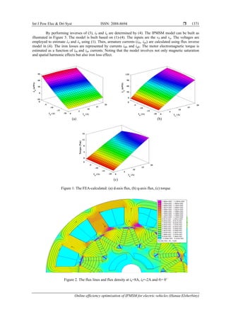
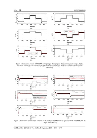
To consider the effect of magnetic saturation and spatial harmonics, λd, λq, and Te are calculated as
functions of id, iq and rotor position θi as illustrated by (2). The relationships λd (id, iq, θi), λq (id, iq, θi), and Te
(id, iq, θi) are calculated using the finite element analysis (FEA). These data are obtained via FEA by varying
id from -20 to 0 A in steps of 1A, iq is changed from from 0 to 20 A in steps of 1A, and θi is varied from 0˚
(d-axis) to 72˚ (q-axis for 12 slots, 10 poles IPMSM) insteps of 1˚ (mech. degree). Then, the average flux-
linkages and torque are obtained according to (3). These results are shown in Figure 1 (a), Figure 1 (b), and
Figure 1 (c). As noted, the flux linkages (λd, λq), and torque show nonlinear relations with currents (id, iq). The
stator pole shoes, and rotor rips have the highest flux densities. They are in deep saturation as illustrated by
Figure 2.
𝜆𝑑 = 𝑓(𝑖𝑑, 𝑖𝑞, 𝜃𝑖), 𝜆𝑞 = 𝑔(𝑖𝑑, 𝑖𝑞, 𝜃𝑖), 𝑇𝑒 = 𝑇(𝑖𝑑, 𝑖𝑞, 𝜃𝑖) (2)
𝜆𝑑(𝑖𝑑, 𝑖𝑞) =
∑ 𝜆𝑑(𝑖𝑑,𝑖𝑞,𝜃𝑖)
𝑁
𝑖=0
𝑁+1
, 𝜆𝑞(𝑖𝑑, 𝑖𝑞) =
∑ 𝜆𝑞(𝑖𝑑,𝑖𝑞,𝜃𝑖)
𝑁
𝑖=0
𝑁+1
, 𝑇𝑒(𝑖𝑑, 𝑖𝑞) =
∑ 𝑇𝑒(𝑖𝑑,𝑖𝑞,𝜃𝑖)
𝑁
𝑖=0
𝑁+1
(3)](https://image.slidesharecdn.com/21311-41374-2-pb-220128042109/85/Online-efficiency-optimization-of-IPMSM-for-electric-vehicles-2-320.jpg)
![ ISSN: 2088-8694
Int J Pow Elec & Dri Syst, Vol. 12, No. 3, September 2021 : 1369 – 1378
1372
vd
-
Σ
+
ida
id (λd, λq)
iq (λd, λq)
1/s
Rs
1/s
Rs
ωe
Σ
ωe
Te
Te(ida, iqa)
λd
λq
-
+
-
+
iqa
vq
Σ
iq-fe
iq +
+
Σ
id-fe
+
+
id
Figure 3. The schematic of IPMSM model
𝑖𝑑 = 𝑓−1
(𝜆𝑑, 𝜆𝑞), 𝑖𝑞 = 𝑔−1
(𝜆𝑑, 𝜆𝑞) (4)
2.2. Loss modeling
This section describes the total system losses including motor and inverter losses. The total system
losses (Ploss) are copper losses (Pcu), fundamental iron losses (PFe, f), harmonic iron losses (PFe, h), magnet loss
(PMag), and inverter losses (Pinv). The total system losses (Ploss) are given by (5).
𝑃𝑙𝑜𝑠𝑠 = 𝑃𝑐𝑢 + 𝑃𝐹𝑒,𝑓 + 𝑃𝐹𝑒,ℎ + 𝑃𝑀𝑎𝑔 + 𝑃𝑖𝑛𝑣 (5)
2.2.1. Copper losses
The fundamental copper loss of an IPMSM can be estimated by (6). The harmonics copper losses
can be ignored as the employed switching frequency of inverter is 10kHz [16].
𝑃𝑐𝑢 = 3𝐼𝑠
2
𝑅𝑠 =
3
2
𝑅𝑠(𝑖𝑑
2
+ 𝑖𝑞
2
) (6)
2.2.2. Iron losses
The Bertotti iron loss formula is a widely used method to evaluate the iron loss in electric machines.
It calculates iron losses per unit volume is being as [23].
𝑃𝑓𝑒 = 𝑘1(𝜆𝑑
2
+ 𝜆𝑞
2
) + 𝑘2(𝜆𝑑
1.5
+ 𝜆𝑞
1.5
), 𝑘1 = (𝑘ℎ𝑓 + 𝑘𝑐𝑓2) (
𝑉𝑡
𝐴𝑡𝑐
2 +
𝑉
𝑦
𝐴𝑦𝑐
2
) , 𝑘2 = 𝑘𝑒𝑓1.5
(
𝑉𝑡
𝐴𝑡𝑐
1.5 +
𝑉
𝑦
𝐴𝑦𝑐
1.5)
𝑉𝑡 = 𝑄ℎ𝑡𝐴𝑡 ; 𝑉
𝑦 = 𝜋(𝐷𝑠 − ℎ𝑦)𝐴𝑦 ; 𝑘𝑐 =
𝜋2𝜎𝑘𝑑
2
6
; 𝜙𝑑,𝑞 =
√2
√3
𝜆𝑑,𝑞
𝑁𝑇𝐾𝑤
(7)
𝐴𝑡𝑐 =
√3
√2
(𝑁𝑇𝐾𝑤). 𝛼𝑖𝐴𝑡𝑄/(2𝑝); 𝐴𝑦𝑐 =
√3
√2
(𝑁𝑇𝐾𝑤). 2𝐴𝑦
where f is the frequency. The coefficients kh, kc, and ke are for hysteresis, eddy current, and additional losses,
respectively. Vt and Vy are the total volumes of stator tooth and yoke, respectively. The Atc and Ayc are the
equivalent areas of stator tooth and yoke, respectively. ht and hy are the heights of stator tooth and yoke,
respectively. Q is the number of slots. At and Ay are the physical areas of stator tooth and yoke, respectively.
Ds is the outer diameter of stator. 𝜎 is the material conductivity. kd is the lamination thickness. NT is the
number of phase turns. Kw is the winding factor. ϕd and ϕq are the d- and q-axis fluxes. αi is the pole arc
factor. Without the consideration of excess loss, the equivalent iron loss resistance Rc is given as Rc = ⍵e
2
/k1.
2.2.3. The harmonic iron loss
It is calculated as a function of ripple voltage rms, ∆𝑉
𝑟𝑚𝑠
2
, DC link voltage Vdc, and modulation index
m as given by (8) [24]. The modulation index is defined as 𝑚 =
√3𝑉𝑚
𝑉𝑑𝑐
.](https://image.slidesharecdn.com/21311-41374-2-pb-220128042109/85/Online-efficiency-optimization-of-IPMSM-for-electric-vehicles-4-320.jpg)
![Int J Pow Elec & Dri Syst ISSN: 2088-8694
Online efficiency optimization of IPMSM for electric vehicles (Hanaa Elsherbiny)
1373
𝑃𝑓𝑒,ℎ = 𝐾ℎ,𝑒𝑑𝑑𝑦∆𝑉
𝑟𝑚𝑠
2
; 𝑤ℎ𝑒𝑟𝑒 ∆𝑉
𝑟𝑚𝑠
2
=
𝑉𝑑𝑐
2
3
(
2
𝜋
𝑚 −
1
2
𝑚2
) (8)
where Vm is the peak output voltage. Kh, eddy is the eddy current loss coefficient, it is taken as 2.3mW/V2
[24].
2.2.4. The magnet loss
The magnet loss depends on magnet volume (VM), magnet width (bM), magnet resistivity (𝜌M), and
the maximum value of flux density (Bm).
𝑃𝑚𝑎𝑔 =
𝑉𝑀 𝑏𝑀
2
𝐵𝑚
2 𝑓2
12𝜌𝑀
(9)
2.2.5. The inverter losses
The inverter has both conduction and switching losses [25]. The conduction loss of one insulated
gate bipolar transistor (IGBT) (Pco-IGBT) and conduction loss for one diode (Pco-diode) in a 2-level VSI can be
defined by (10). Besides, the switching losses of one IGBT (PSW-IGBT) and switching loss for one diode (PSW-
diode) in a 2-level VSI can be defined by (11) [26]. The total inverter losses (Pinv) can be estimated by (12).
𝑃𝑐𝑜_𝐼𝐺𝐵𝑇 =
1
2
(𝑉
𝑐𝑒𝑜
𝐼𝑚
𝜋
+ 𝑅𝑜
𝐼𝑚
2
4
) + 𝑚 𝑐𝑜𝑠 𝜃 (𝑉
𝑐𝑒𝑜
𝐼𝑚
8
+ 𝑅𝑜
𝐼𝑚
2
3𝜋
)
(10)
𝑃𝑐𝑜_𝑑𝑖𝑜𝑑𝑒 =
1
2
(𝑉𝐷𝑜
𝐼𝑚
𝜋
+ 𝑅𝐷
𝐼𝑚
2
4
) − 𝑚 𝑐𝑜𝑠 𝜃 (𝑉𝐷𝑜
𝐼𝑚
8
+ 𝑅𝐷
𝐼𝑚
2
3𝜋
)
𝑃𝑆𝑊−𝐼𝐺𝐵𝑇 =
1
𝜋
(𝑒𝑜𝑛 + 𝑒𝑜𝑓𝑓)𝑓𝑠 (
𝑉𝑑𝑐
𝑉𝑛𝑜𝑚
) (
𝐼𝑚
𝐼𝑛𝑜𝑚
) ; 𝑃𝑆𝑊−𝑑𝑖𝑜𝑑𝑒 =
1
𝜋
𝑒𝑟𝑟𝑓𝑠 (
𝑉𝑑𝑐
𝑉𝑛𝑜𝑚
) (
𝐼𝑚
𝐼𝑛𝑜𝑚
) (11)
𝑃𝑖𝑛𝑣 = 6 ∗ ((𝑃𝑐𝑜−𝐼𝐺𝐵𝑇 + 𝑃𝑐𝑜−𝑑𝑖𝑜𝑑𝑒) + (𝑃𝑆𝑊−𝐼𝐺𝐵𝑇 + 𝑃𝑆𝑊−𝑑𝑖𝑜𝑑𝑒)) (12)
where cosθ is the power factor, Vceo and VDo depict the threshold voltages for IGBT and diode, respectively,
Ro and RD represent the resistances of IGBT and diode, respectively, fs is the switching frequency, eon and eoff
are the required amount of energy to turn-on and turn-off the IGBT, respectively, err is the required amount
of energy to turn-off the diode, Im is the peak magnitude of current, Vnom and Inom are the nominal voltage and
current of loss measurements, respectively.
3. THE PROPOSED ONLINE EFFICIENCY OPTIMIZATION METHOD
The proposed OMEPA control determines the current angle (𝛽) that maximizes the system
efficiency. The flowchart of searching algorithm is illustrated in Figure 4. The procedure is achieved online
for a known maximum current (Im), and motor speed (⍵). For each operating point, the current angle is
changed in small steps (Δ𝛽). The d- and q-axis current components are estimated by (13). Then, the total
system losses (Ploss) are estimated using (5)-(12). After that, the system efficiency (ƞ) is updated by (13)
considering the voltage and current constraints in (14). The online efficiency calculation should also consider
the variations in temperature, DC voltage, and motor parameters.
− Measure DC voltage (Vdc), speed (ω), and temperature.
− The winding resistance is updated as a function of temperature using (15).
− For each current angle 𝛽, the d- and q-axis current components are calculated using (13).
− The d- and q-axis flux linkages are updated using (16).
− The d- and q-axis voltage components are updated using (17).
− The system losses are estimated using (5)-(12).
− The online system efficiency is updated using (13) considering the voltage and current constraints in (14).
− If 𝛽≥ 𝛽max, determine angle that corresponds to maximum efficiency. Else, 𝛽 is changed by Δ𝛽, then go to
point 2.](https://image.slidesharecdn.com/21311-41374-2-pb-220128042109/85/Online-efficiency-optimization-of-IPMSM-for-electric-vehicles-5-320.jpg)
![ ISSN: 2088-8694
Int J Pow Elec & Dri Syst, Vol. 12, No. 3, September 2021 : 1369 – 1378
1374
Start
Calculate the direct and quadrature flux linkages
Calculate the steady-state voltage considering the
saturation effect according to (17).
Enter the desired speed and peak current
β = βinitial
Calculate the direct and quadrature currents (id , iq )
Calculate the total system losses (fundamental and
harmonic motor losses + inverter losses) using (5)
Update torque and efficiency modeling considering
saturation and cross saturation and iron losses.
Yes
β = β + Δβ
β ≤ βmax
Output the optimal current angle for maximum
efficiency
End
No
Figure 4. The Flowchart of searching algorithm
The temperature directly affects the stator resistance and hence the amount of copper loses. The
temperature effect is included considering (15). The DC voltage is measured instantaneously each sample
time. The motor parameters are fitted as functions of d-and q-axis current components. At each operating
point, defined by ⍵ and Im, 𝛽 angle corresponding to maximum efficiency is reported.
𝑖𝑑 = −𝐼𝑚 𝑠𝑖𝑛 𝛽; 𝑖𝑞 = 𝐼𝑚 𝑐𝑜𝑠 𝛽; ƞ =
𝑇𝑒∗⍵
𝑇𝑒∗⍵ + 𝑃𝑙𝑜𝑠𝑠
; (13)
√𝑉𝑑
2
+ 𝑉
𝑞
2 ≤ 𝑉
𝑚𝑎𝑥; √𝑖𝑑
2
+ 𝑖𝑞
2 ≤ 𝐼𝑚𝑎𝑥 (14)
𝑅 = 𝑅𝑜{1 + 𝛼(𝑇 − 𝑇𝑜)} (15)
𝜆𝑑(𝑖𝑑, 𝑖𝑞) = 𝐿𝑑(𝑖𝑑, 𝑖𝑞)𝑖𝑑 + 𝜆𝑝𝑚(𝑖𝑞); 𝜆𝑞(𝑖𝑑, 𝑖𝑞) = 𝐿𝑞(𝑖𝑑, 𝑖𝑞)𝑖𝑞 (16)
𝑣𝑑(𝑖𝑑, 𝑖𝑞) = 𝑅𝑖𝑑 − ⍵𝑒𝜆𝑞(𝑖𝑑, 𝑖𝑞); 𝑣𝑞(𝑖𝑑, 𝑖𝑞) = 𝑅𝑖𝑞 + ⍵𝑒𝜆𝑑(𝑖𝑑, 𝑖𝑞) (17)
where Vmax and Imax are the maximum permissible phase voltage and phase current, respectively. Ro depicts
the winding resistance at temperature To. T is the present temperature of windings. α is the thermal coefficient
of copper. Ld and Lq are d- axis and q- axis inductances. λPM is the PM flux linkage.
4. RESULTS AND DISSCUSSION
The results include a steady state comparison between proposed OMEPA control method and offline
maximum efficiency per ampere-lookup table (MEPA-LUT) control method reported in Ni et al [18].
Moreover, the dynamic behavior of OMEPA is presented and analyzed. The influence of DC voltage
variation, temperature variation, and the variation of motor parameters is also investigated.](https://image.slidesharecdn.com/21311-41374-2-pb-220128042109/85/Online-efficiency-optimization-of-IPMSM-for-electric-vehicles-6-320.jpg)

![Int J Pow Elec & Dri Syst ISSN: 2088-8694
Online efficiency optimization of IPMSM for electric vehicles (Hanaa Elsherbiny)
1377
4.4. Effect of temperature and motor parameter variations
The IPMSMs in EVs have temperature sensors that are installed in stator windings. These sensors
provide instantaneous temperature variations not only for protection issues but also for control ones. The
winding resistance of IPMSM changes with the temperature as illustrated by (15). The change of stator
resistance will affect the amount of copper losses. Hence, it affects the accuracy of efficiency calculation for
both the online and offline calculations.
The offline MEPA control methods assumes constant stator resistance. When the temperature
increases, the resistance will also increase, and hence the copper losses. Therefore, the offline MEPA method
will deviate from the MEPA operation. In order to include the effect of temperature within the offline MEPA
control, several experimental measurements are required which means cost, effort, and time. On the contrary,
once the temperature is measured by the temperature sensors, the stator resistance is updated using (15)
within the control algorithm of the proposed OMEPA. This is a very simple implementation method that
compensates for the resistance variation due to the temperature.
Figure 8 (a), and Figure 8 (b) shows the effect of temperature on both copper loss and efficiency,
respectively. The amount of copper losses considering temperature effect (Pcu-CTE) is greater than that without
considering temperature effect (Pcu-WCTE) as illustrated by Figure 8 (a). The corresponding system efficiency
at 10A is shown in Figure 8 (b), as seen, the proposed OMEPA has higher system efficiency as it considers
the real amount of copper losses due to temperature variations. If the motor parameters changes, they can be
considered within the control algorithm of OMEPA by the same way the temperature is considered. Online
parameter estimation methods can be used to estimate the accurate motor parameters, then, theses parameters
can be used very simply within the OMEPA control.
(a) (b)
Figure 8. Effect of temperature variation on copper losses and efficiency, (a) copper losses, and (b) system
efficiency at 1000r/min and at 100⁰C
5. CONCLUSION
An online maximum efficiency control method for IPMSM in EVs is introduced in this paper. The
system efficiency is calculated online based on the detailed system loss models. A searching algorithm for
the current angle that corresponds to maximum efficiency point is developed. The proposed OMEPA control
offers high dynamic performance as it updates the current angle at each control period. It also offers higher
flexibility as it can consider any instantaneous variations of DC voltage (battery voltage), temperature, and
motor parameters. The proposed OMEPA control method is independent in tracking the maximum efficiency
point as well as robust to DC voltage variations.
REFERENCES
[1] F. Aymen, M. Alowaidi, M. Bajaj, N. K. Sharma, S. Mishra, and S. K. Sharma, “Electric vehicle model based on
multiple recharge system and a particular traction motor conception,” IEEE Access, vol. 9, pp. 49308-49324, 2021,
doi: 10.1109/ACCESS.2021.3068262.
[2] L. Dang, N. Bernard, N. Bracikowski, and G. Berthiau, “Design optimization with flux weakening of high-speed
PMSM for electrical vehicle considering the driving cycle,” IEEE Transactions on Industrial Electronics, vol. 64,
no. 12, pp. 9834-9843, Dec. 2017, doi: 10.1109/TIE.2017.2726962.
[3] A. Flah, M. Novak, and S. Lassaad, “An improved reactive power MRAS speed estimator with optimization for a
hybrid electric vehicles application,” ASME, Journal of Dynamic Systems, Measurement, and Control, vol. 140, no.
6, p. 061016, 2018, doi: 10.1115/1.4039212.
[4] X. Chen, “Modelling and design of permanent-magnet machines for electric vehicle traction,” thesis, Department of
Electronic and Electrical Engineering, The University of Sheffield, 2015.
[5] C. T. Krasopoulos, M. E. Beniakar, and A. G. Kladas, “Multicriteria PM motor design based on ANFIS evaluation
of EV driving cycle efficiency,” IEEE Transactions on Transportation Electrification, vol. 4, no. 2, pp. 525-535,
June 2018, doi: 10.1109/TTE.2018.2810707.
[6] A. Flah and L. Sbita, “Overview on BLAC and BLDC motors: designs and mathematical modeling,” International
Journal of Powertrains, vol. 9, no. 5, pp. 239-243, 2021.](https://image.slidesharecdn.com/21311-41374-2-pb-220128042109/85/Online-efficiency-optimization-of-IPMSM-for-electric-vehicles-9-320.jpg)
![ ISSN: 2088-8694
Int J Pow Elec & Dri Syst, Vol. 12, No. 3, September 2021 : 1369 – 1378
1378
[7] H. Hanene, A. Flah, and T. Souhir, “Variable reluctance synchronous machines in saturated mode,” International
Journal of Power Electronics and Drive Systems (IJPEDS), vol. 12, no. 2, pp. 662-673 June 2021, doi:
10.11591/ijpeds.v12.i2.pp662-673.
[8] C. Lu, S. Ferrari, and G. Pellegrino, “Two design procedures for PM synchronous machines for electric
powertrains,” IEEE Transactions on Transportation Electrification, vol. 3, no. 1, pp. 98-107, March 2017, doi:
10.1109/TTE.2016.2646738.
[9] J. Wu, J. Wang, C. Gan, Q. Sun, and W. Kong, “Efficiency optimization of PMSM drives using field-circuit
coupled FEM for EV/HEV applications,” IEEE Access, vol. 6, pp. 15192-15201, 2018, doi:
10.1109/ACCESS.2018.2813987.
[10] W. Deng, Y. Zhao, and J. Wu, “Energy efficiency improvement via bus voltage control of inverter for electric
vehicles,” IEEE Transactions on Vehicular Technology, vol. 66, no. 2, pp. 1063-1073, Feb. 2017, doi:
10.1109/TVT.2016.2555990.
[11] J. O. Estima and A. J. M. Cardoso, “Efficiency analysis of drive train topologies applied to electric/hybrid
vehicles,” IEEE Transactions on Vehicular Technology, vol. 61, no. 3, pp. 1021-1031, March 2012, doi:
10.1109/TVT.2012.2186993.
[12] X. Zhou, Y. Zhou, H. Wang, M. Lu, F. Zeng, and Y. Yu, “An improved MTPA control based on amplitude-
adjustable square wave injection,” IEEE Transactions on Energy Conversion, vol. 35, no. 2, pp. 956-965, June
2020, doi: 10.1109/TEC.2020.2968737.
[13] C. Lai, G. Feng, K. Mukherjee, J. Tjong and N. C. Kar, “Maximum torque per ampere control for IPMSM using
gradient descent algorithm based on measured speed harmonics,” IEEE Transactions on Industrial Informatics, vol.
14, no. 4, pp. 1424-1435, April 2018, doi: 10.1109/TII.2017.2759812.
[14] K. Li and Y. Wang, “Maximum torque per ampere (MTPA) control for IPMSM drives based on a variable-
equivalent-parameter MTPA control law,” IEEE Transactions on Power Electronics, vol. 34, no. 7, pp. 7092-7102,
July 2019, doi: 10.1109/TPEL.2018.2877740.
[15] H. Wang, C. Li, G. Zhang, Q. Geng, and T. Shi, “Maximum torque per ampere (MTPA) control of IPMSM systems
based on controller parameters self-modification,” IEEE Transactions on Vehicular Technology, vol. 69, no. 3, pp.
2613-2620, March 2020, doi: 10.1109/TVT.2020.2968133.
[16] A. Balamurali, G. Feng, A. Kundu, H. Dhulipati and N. C. Kar, “Noninvasive and improved torque and efficiency
calculation toward current advance angle determination for maximum efficiency control of PMSM,” IEEE
Transactions on Transportation Electrification, vol. 6, no. 1, pp. 28-40, March 2020, doi:
10.1109/TTE.2019.2962333.
[17] A. Balamurali, G. Feng, C. Lai, J. Tjong, and N. C. Kar, “Maximum efficiency control of PMSM drives
considering system losses using gradient descent algorithm based on DC power measurement,” IEEE Transactions
on Energy Conversion, vol. 33, no. 4, pp. 2240-2249, Dec. 2018, doi: 10.1109/TEC.2018.2852219.
[18] R. Ni, D. Xu, G. Wang, L. Ding, G. Zhang, and L. Qu, “Maximum efficiency per ampere control of permanent-
magnet synchronous machines,” IEEE Transactions on Industrial Electronics, vol. 62, no. 4, pp. 2135-2143, April
2015, doi: 10.1109/TIE.2014.2354238.
[19] M. N. Uddin and R. S. Rebeiro, “Online efficiency optimization of a fuzzy-logic-controller-based IPMSM drive,”
IEEE Transactions on Industry Applications, vol. 47, no. 2, pp. 1043-1050, March-April 2011, doi:
10.1109/TIA.2010.2103293.
[20] S. Yang, K. Liu, Y. Hu, L. Chu and S. Chen, “Efficiency optimization control of IPMSM considering varying
machine parameters,” in 2018 IEEE Student Conference on Electric Machines and Systems, 2018, pp. 1-6, doi:
10.1109/SCEMS.2018.8624761.
[21] M. Li, S. Huang, X. Wu, K. Liu, X. Peng, and G. Liang, “A virtual HF signal injection based maximum efficiency
per ampere tracking control for IPMSM drive,” IEEE Transactions on Power Electronics, vol. 35, no. 6, pp. 6102-
6113, June 2020, doi: 10.1109/TPEL.2019.2951754.
[22] H. Kim, Y. Lee, S. Sul, J. Yu, and J. Oh, “Online MTPA control of IPMSM based on robust numerical optimization
technique,” IEEE Transactions on Industry Applications, vol. 55, no. 4, pp. 3736-3746, July-Aug. 2019, doi:
10.1109/TIA.2019.2904567.
[23] D. Lin, P. Zhou, W. N. Fu, Z. Badics, and Z. J. Cendes, “A dynamic core loss model for soft ferromagnetic and
power ferrite materials in transient finite element analysis,” IEEE Transactions on Magnetics, vol. 40, no. 2, pp.
1318-1321, March 2004, doi: 10.1109/TMAG.2004.825025.
[24] M. Schweizer, T. Friedli, and J. W. Kolar, “Comparative evaluation of advanced three-phase three-level
inverter/converter topologies against two-level systems,” IEEE Transactions on Industrial Electronics, vol. 60, no.
12, pp. 5515-5527, Dec. 2013, doi: 10.1109/TIE.2012.2233698.
[25] M. Saur, B. Piepenbreier, W. Xu, and R. D. Lorenz, “Implementation and evaluation of inverter loss modeling as
part of DB-DTFC for loss minimization each switching period,” in 2014 16th European Conference on Power
Electronics and Applications, 2014, pp. 1-10, doi: 10.1109/EPE.2014.6910691.
[26] J. Guo, “Modeling and design of inverters using novel power loss calculation and dc-link current/voltage ripple
estimation methods and bus bar analysis,” Ph.D. dissertation, Electrical and Computer Engineering, McMaster
University, 2017.](https://image.slidesharecdn.com/21311-41374-2-pb-220128042109/85/Online-efficiency-optimization-of-IPMSM-for-electric-vehicles-10-320.jpg)


