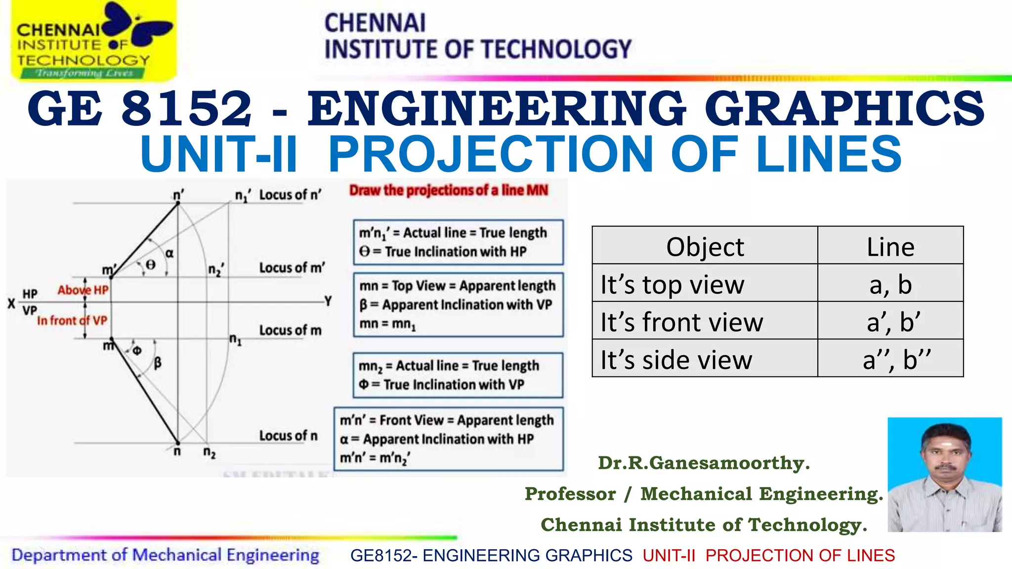
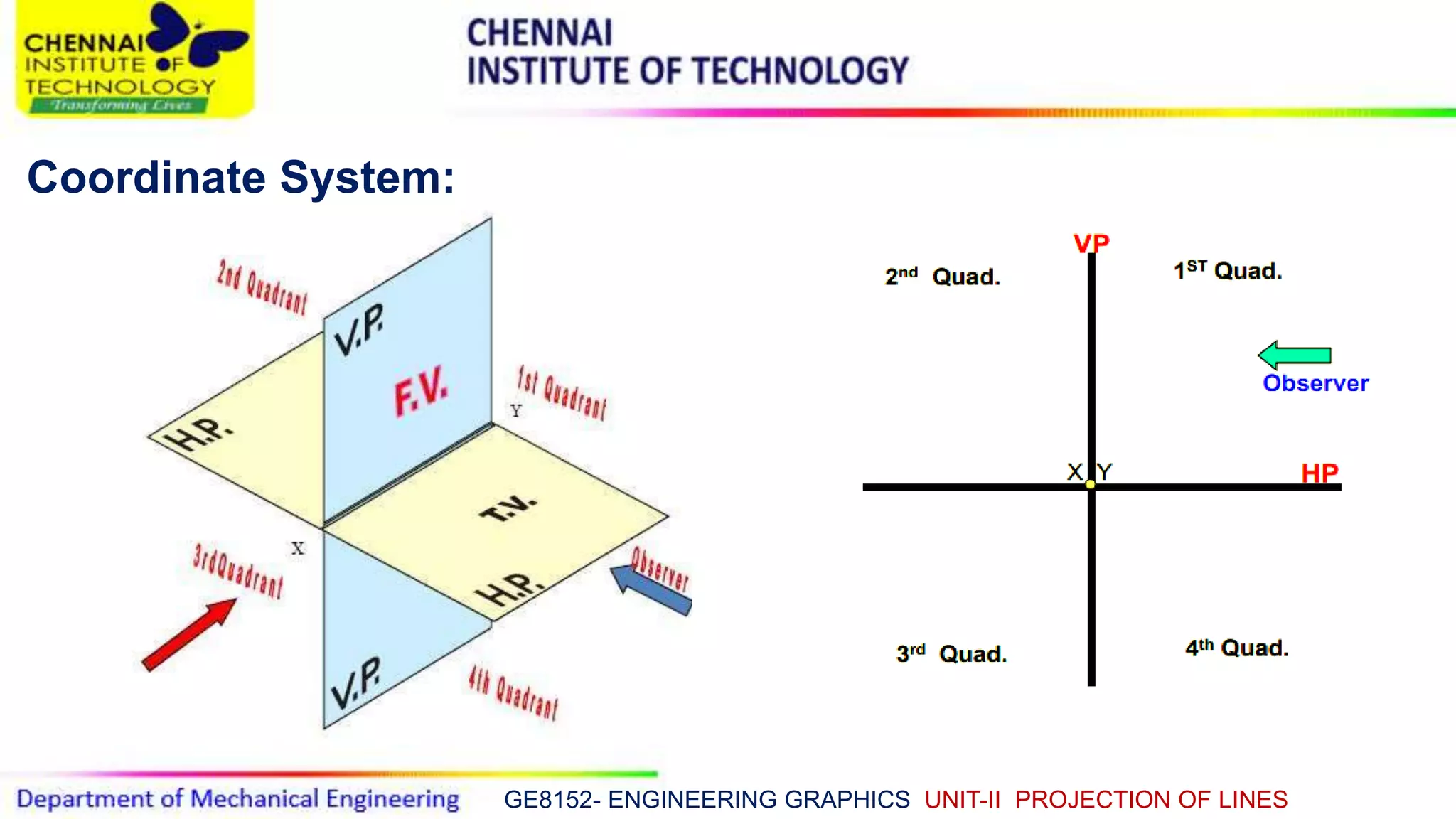
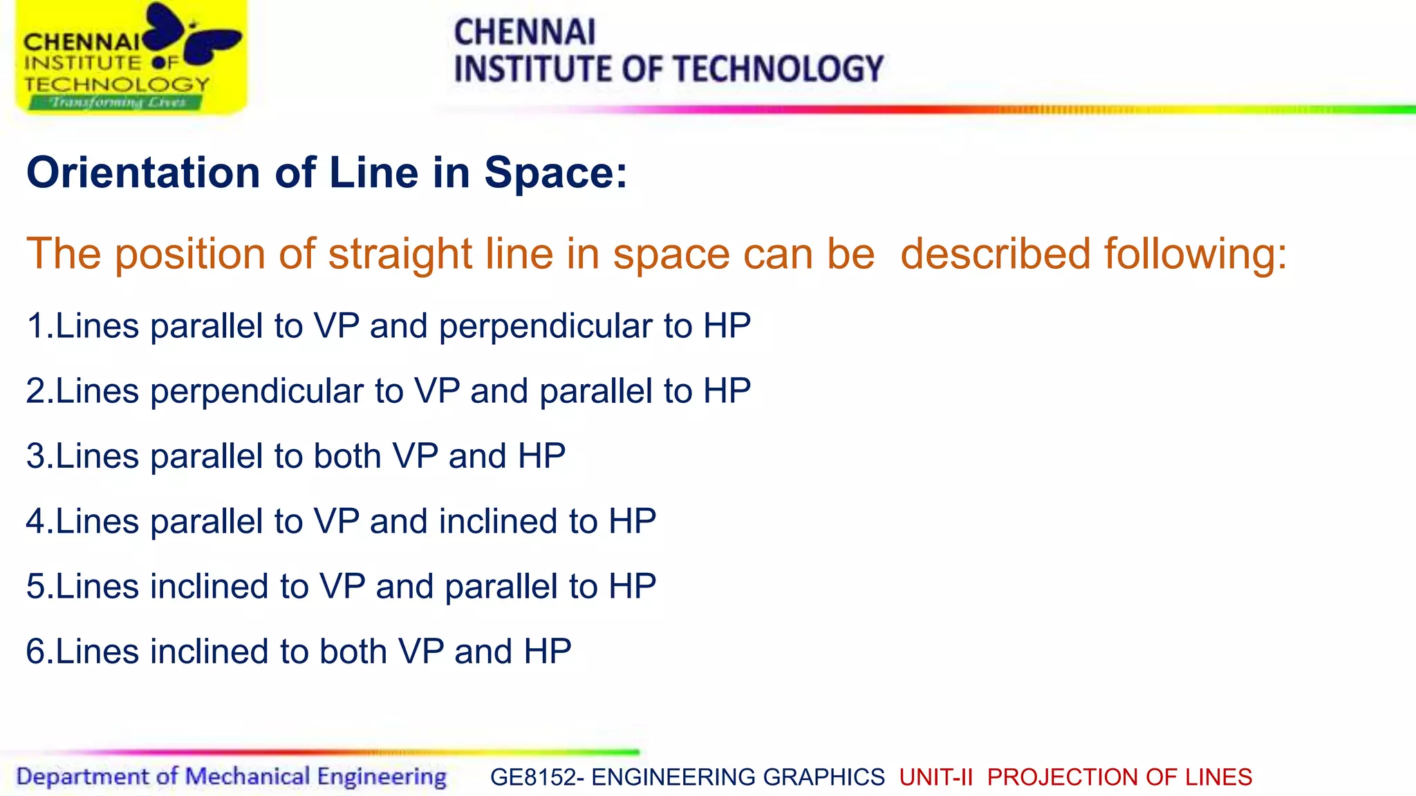
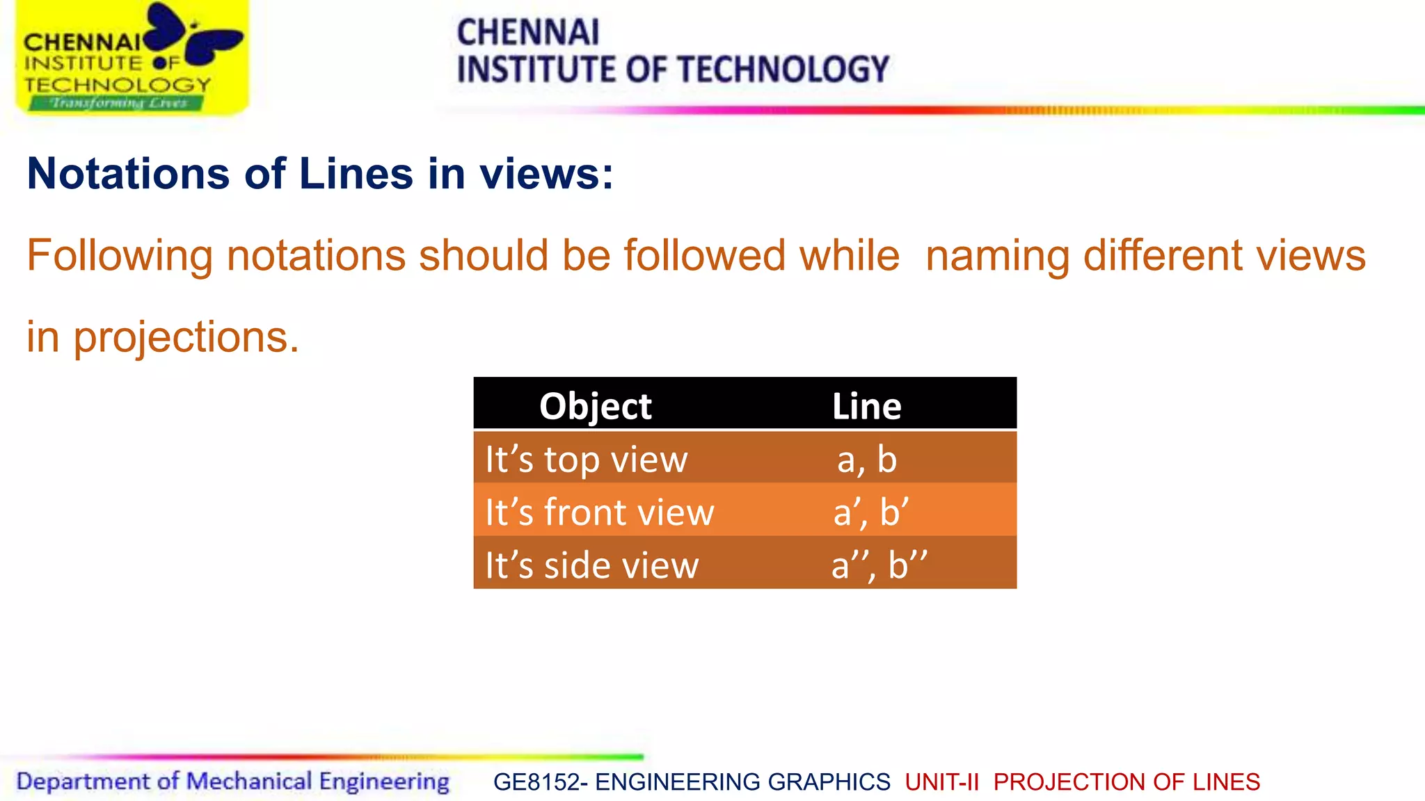
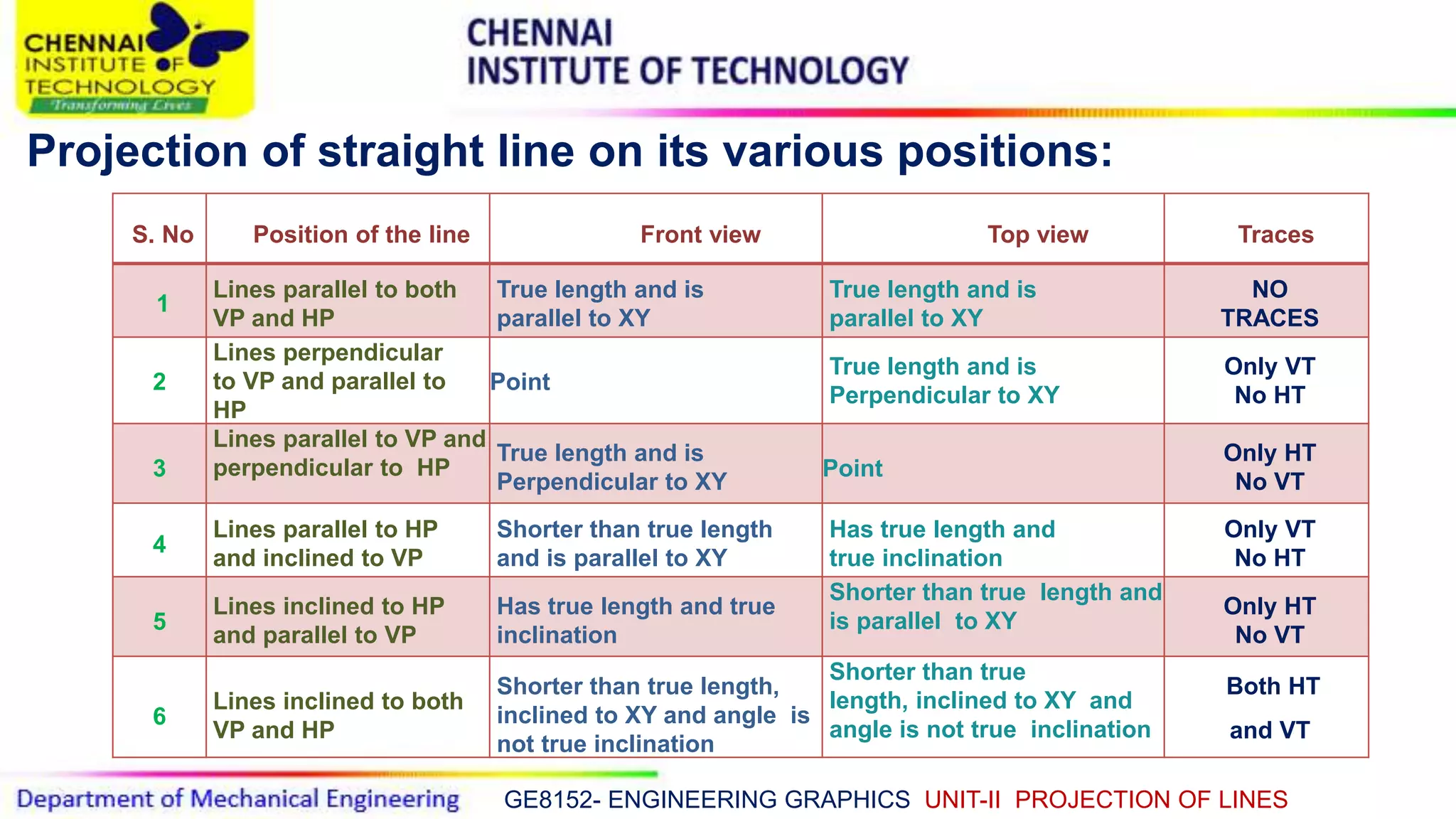
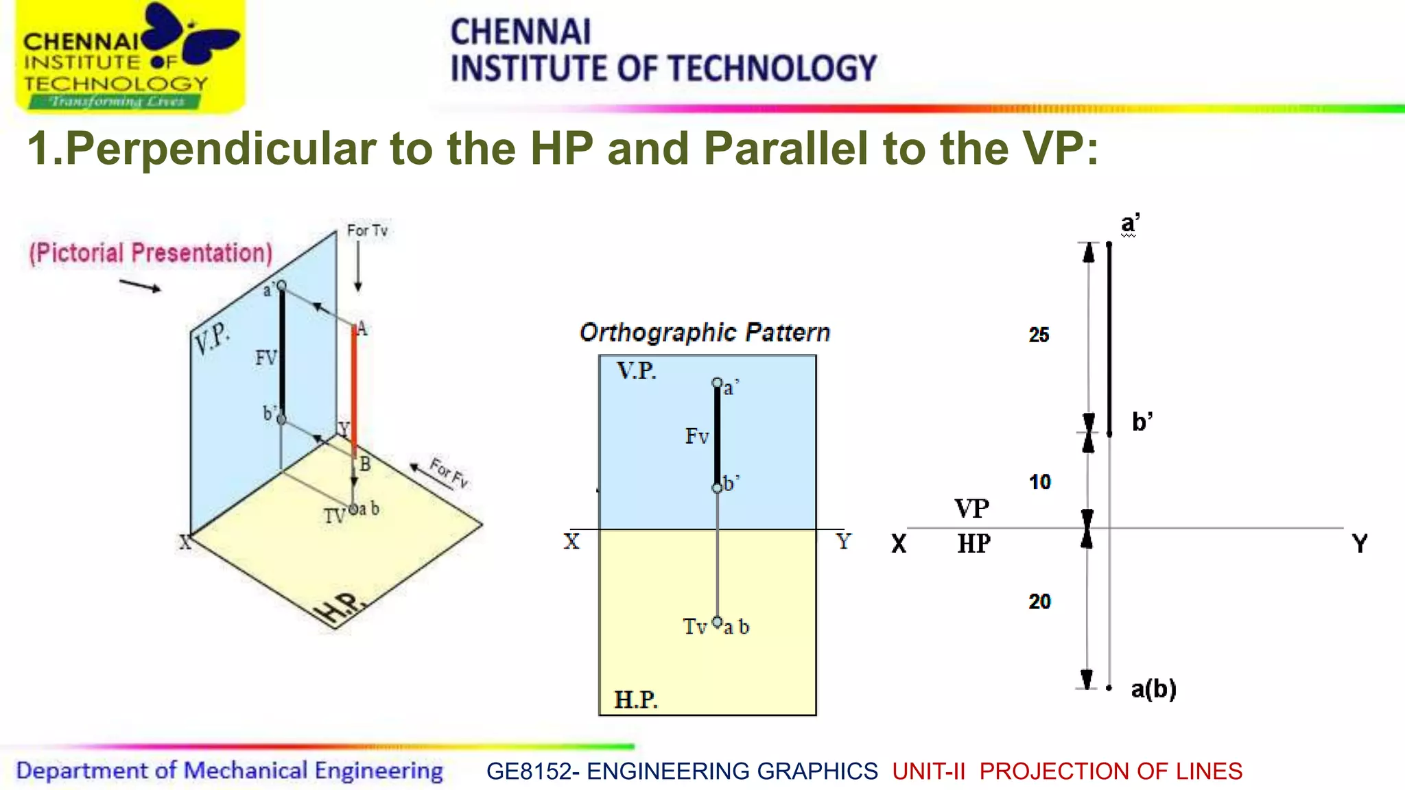
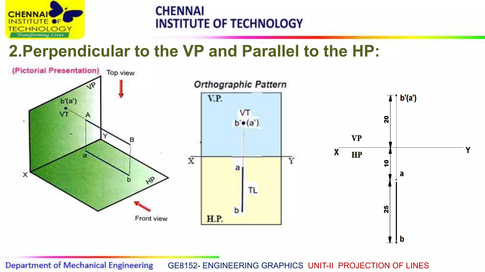
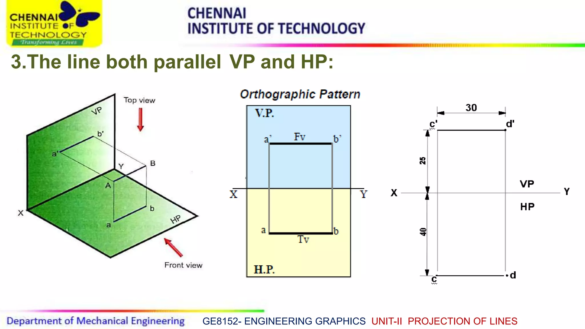
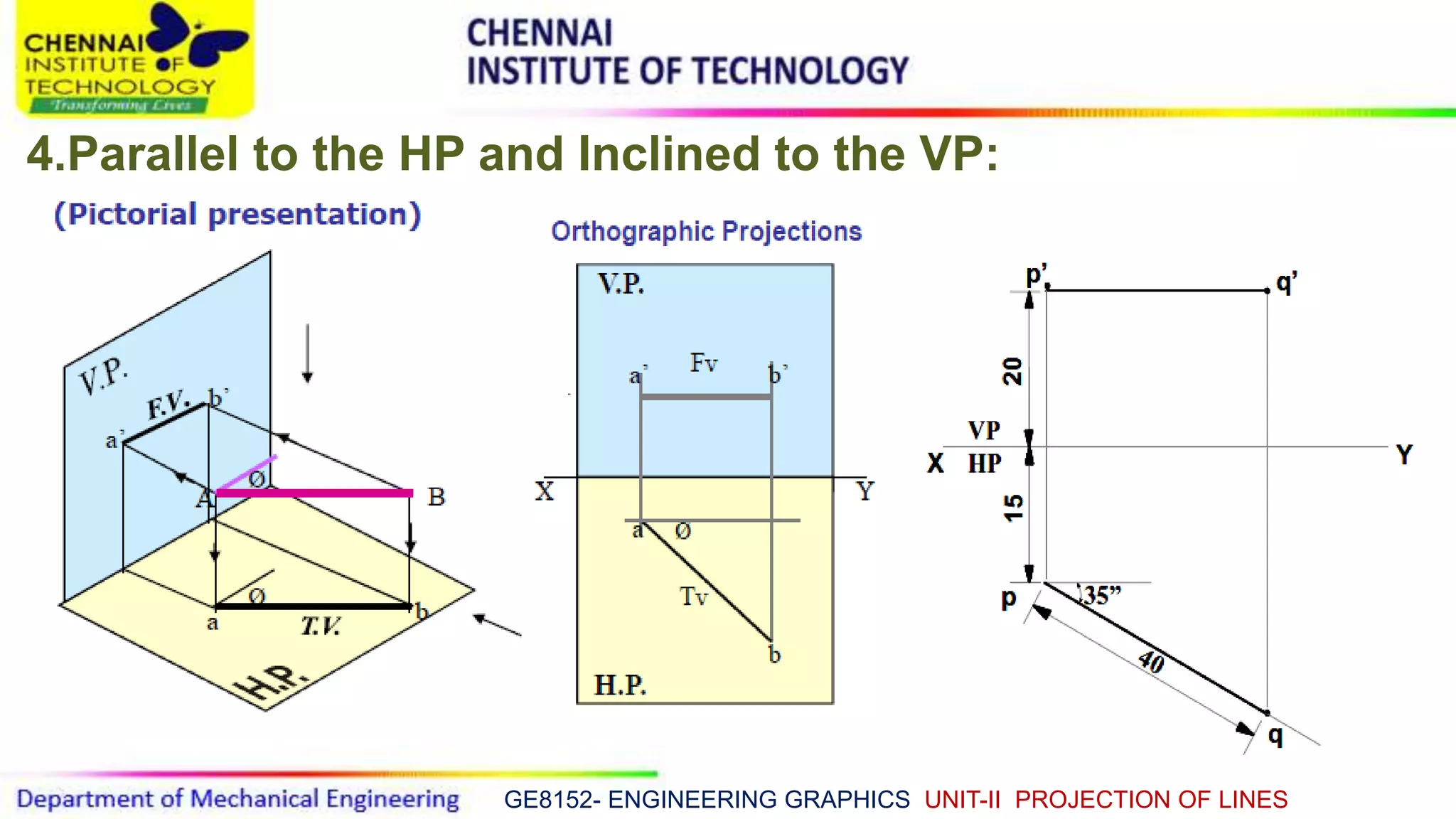
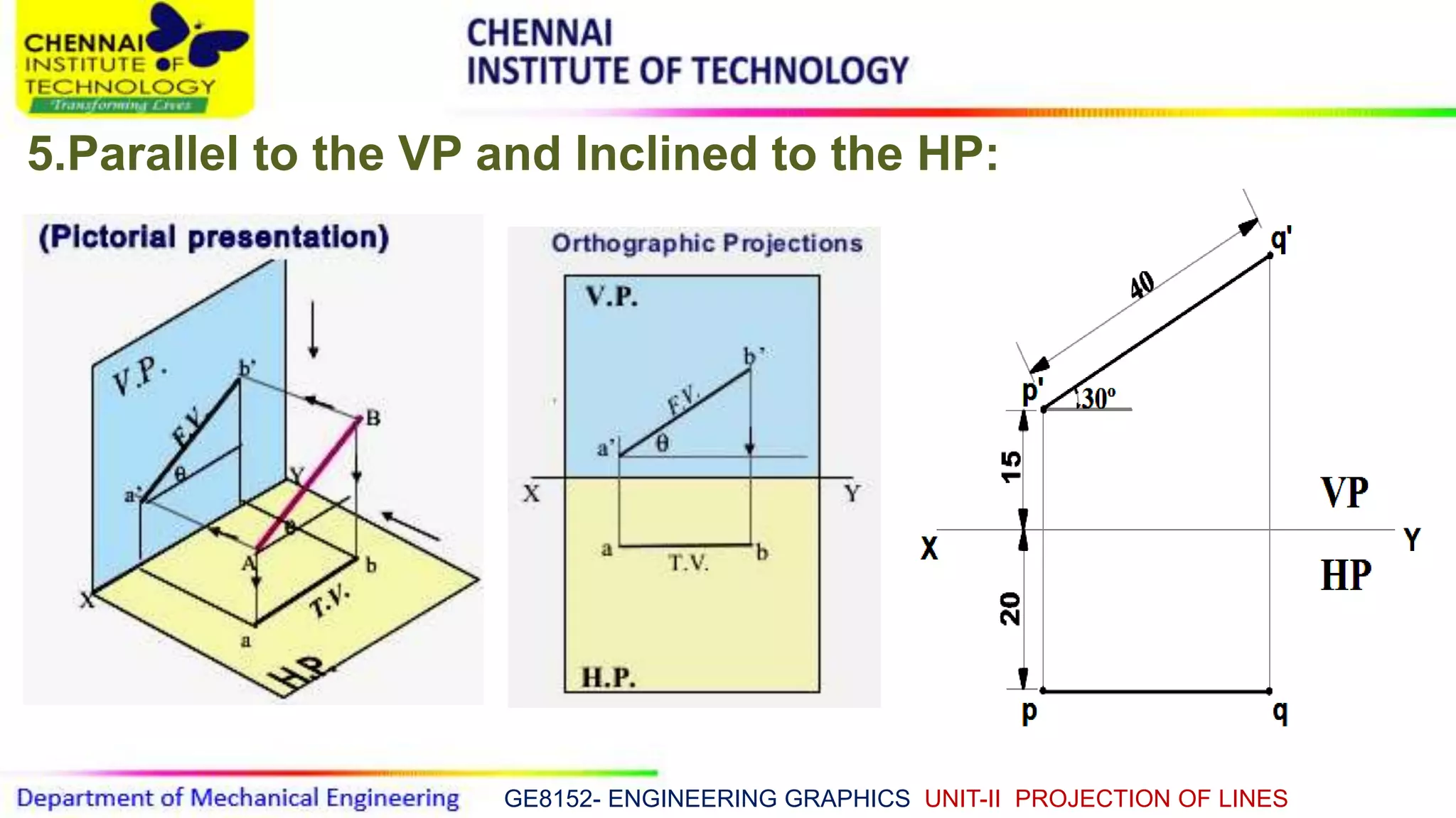
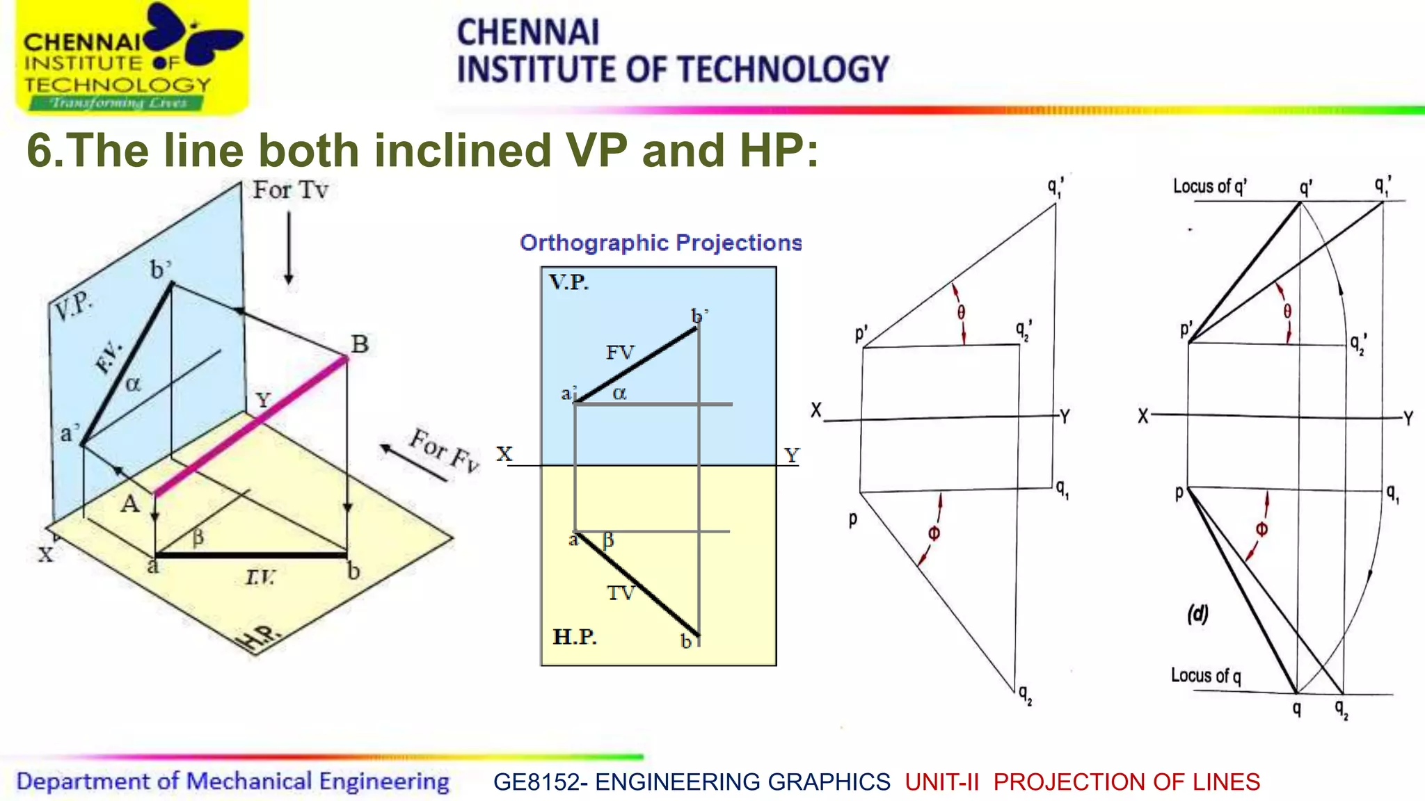
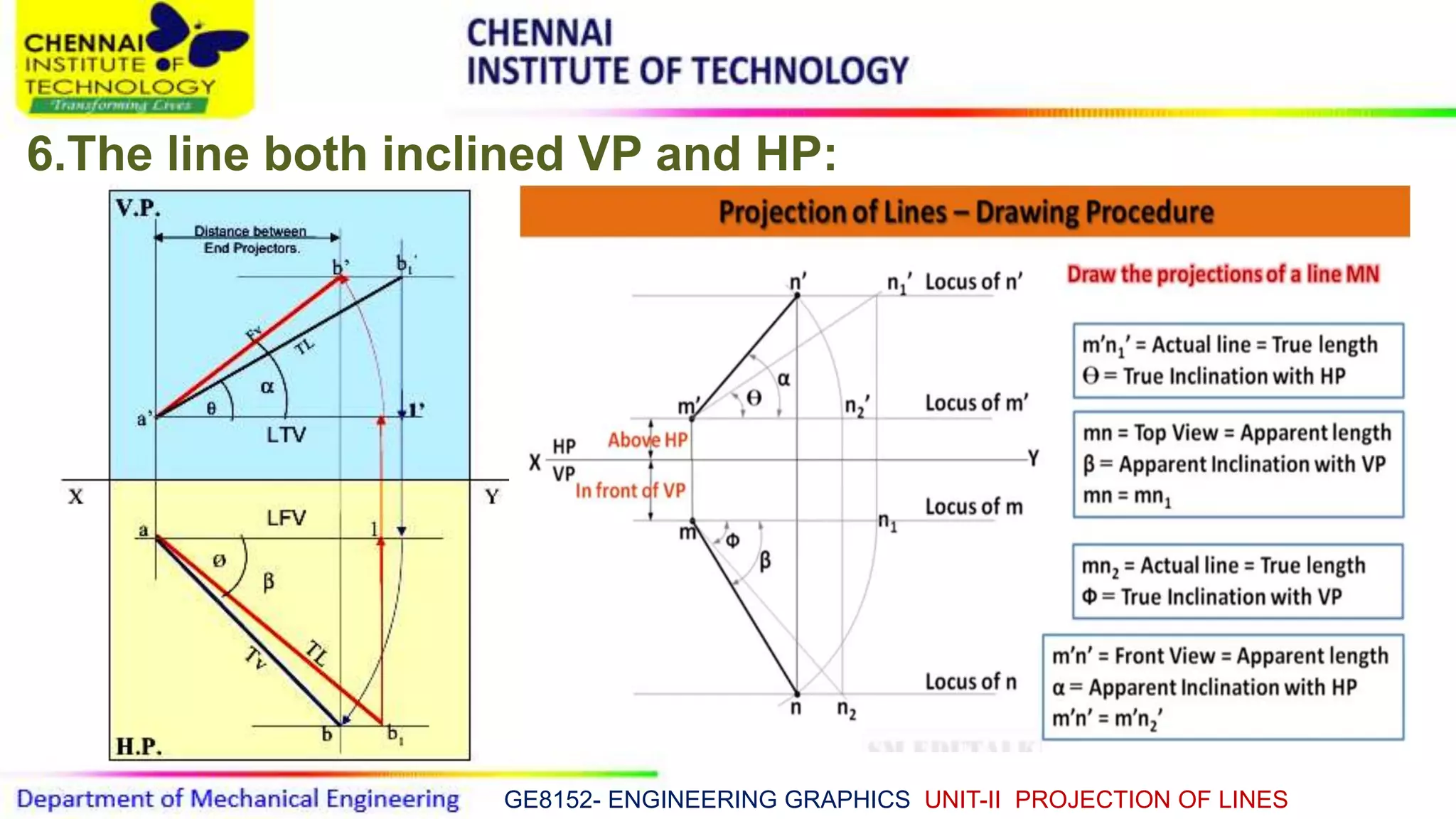
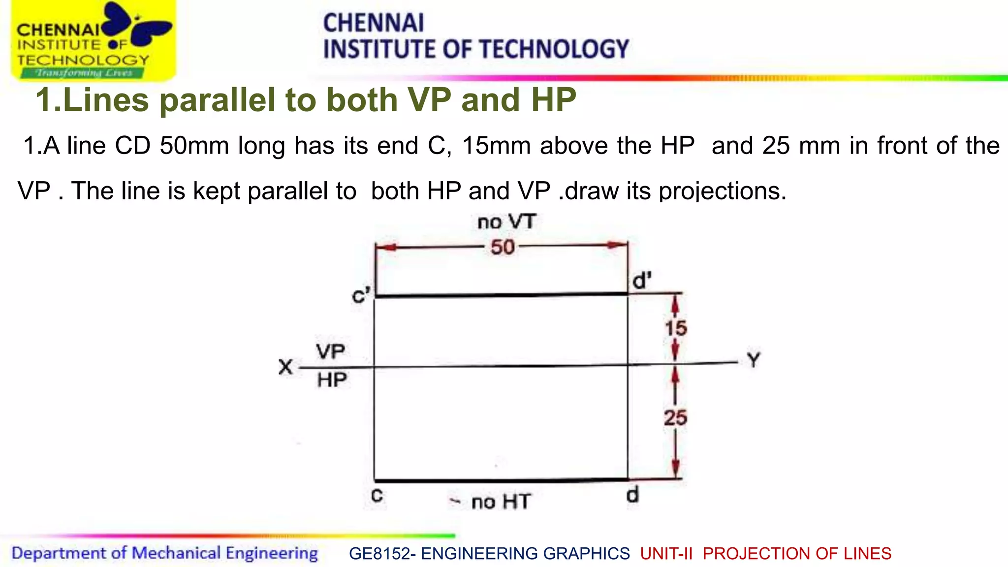
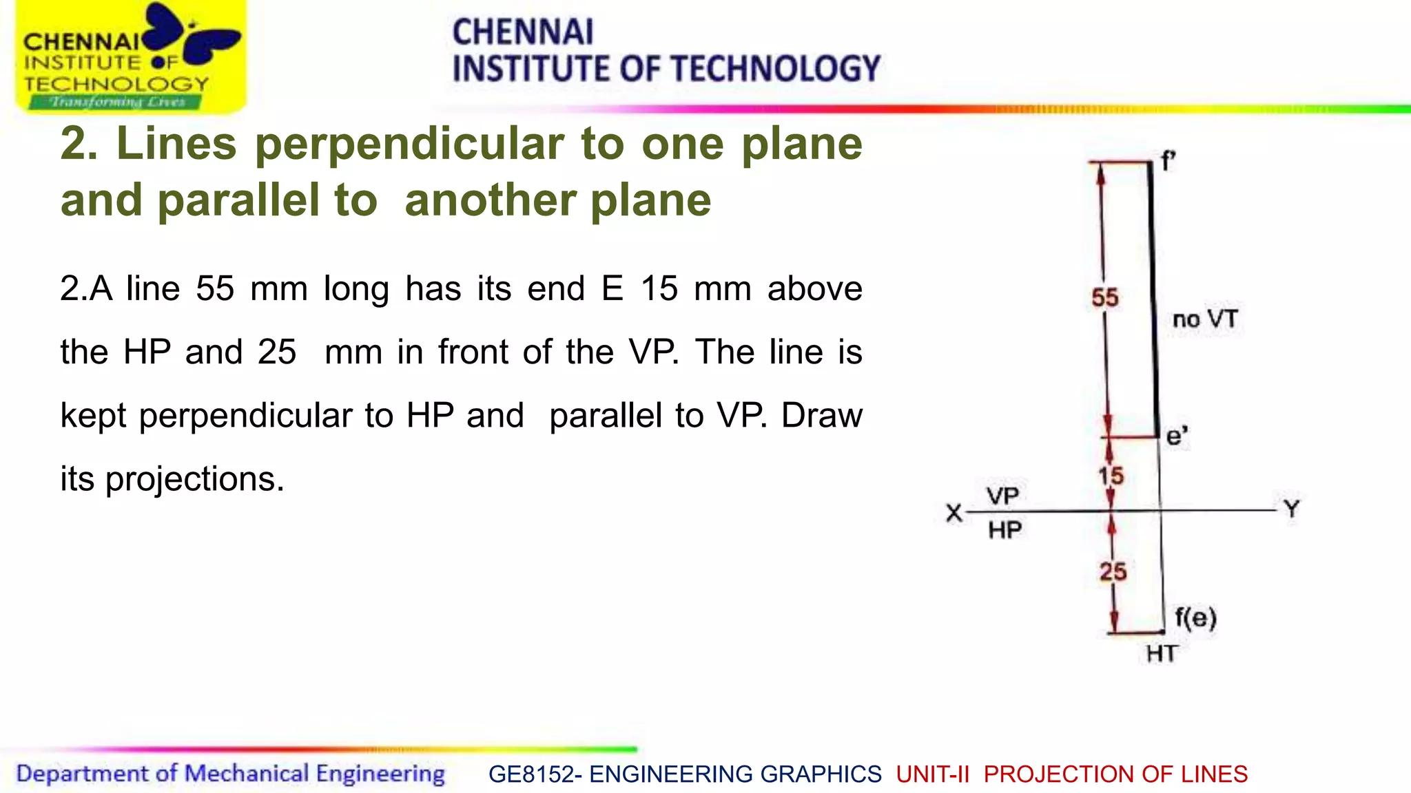
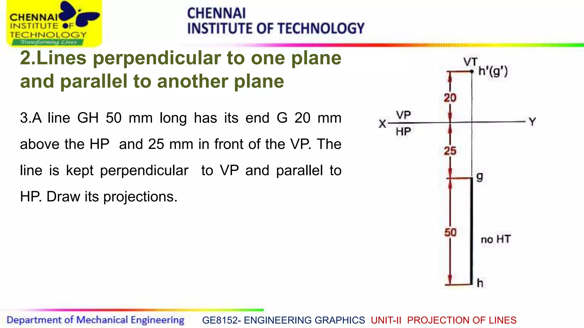
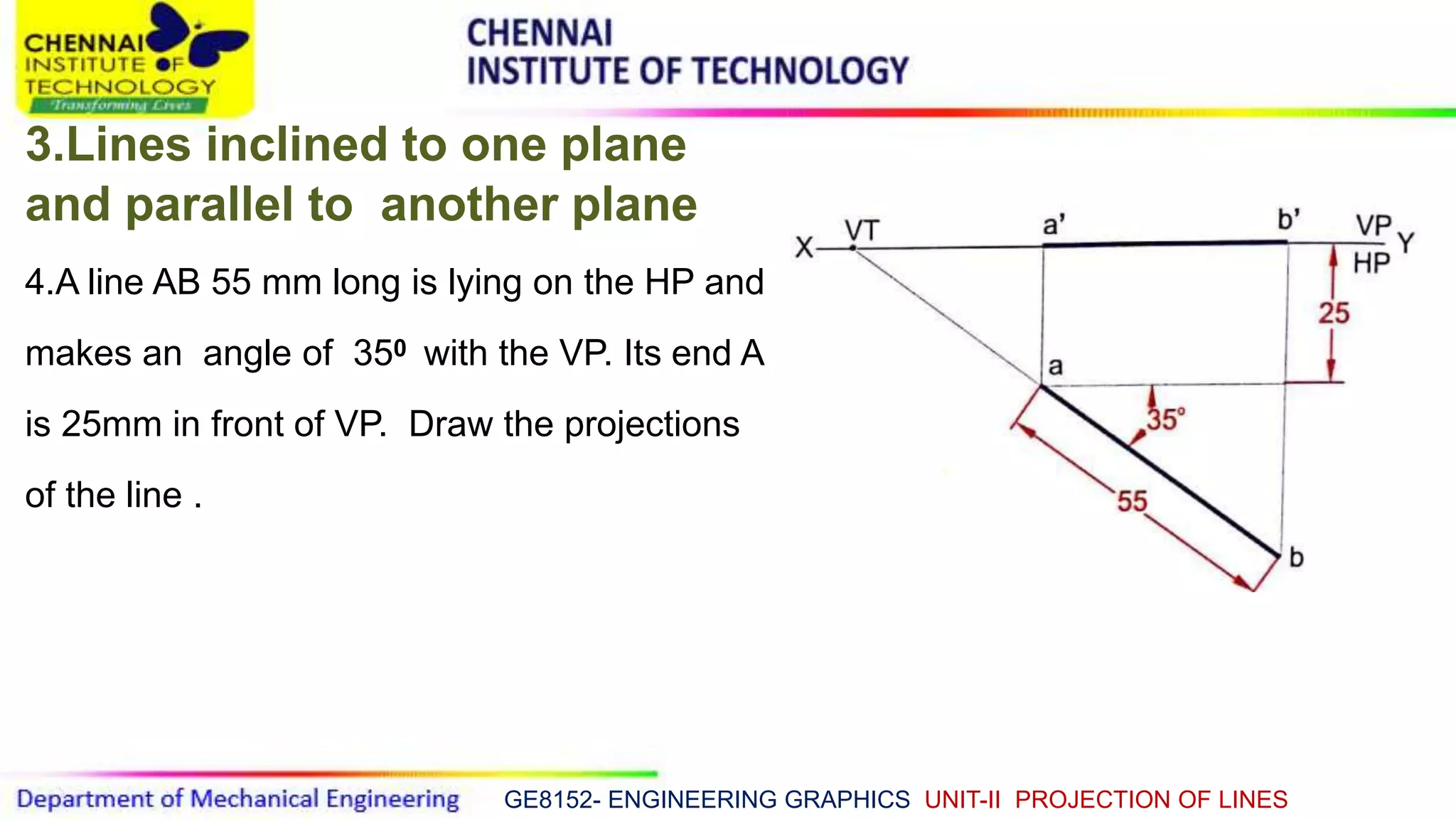
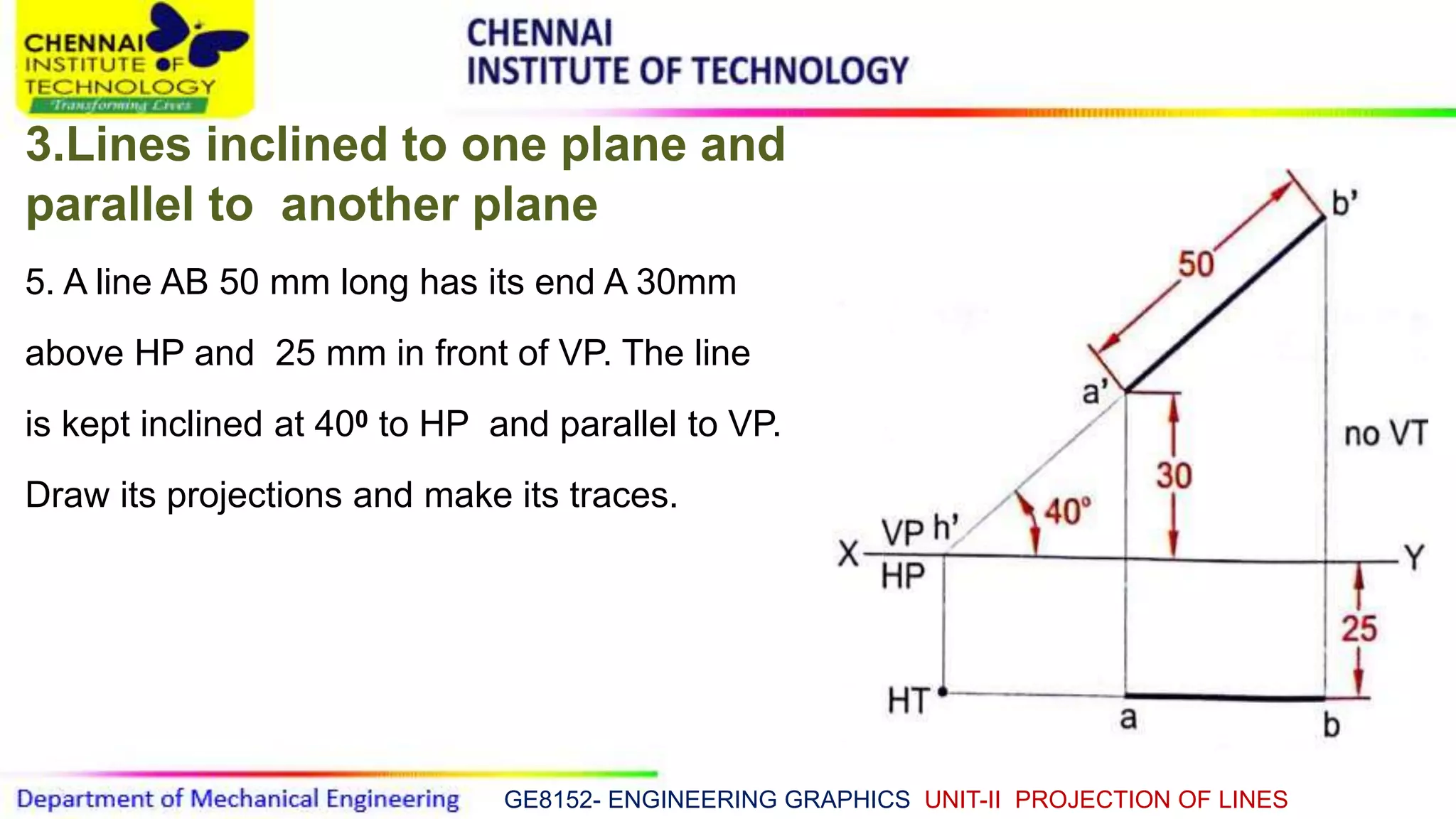
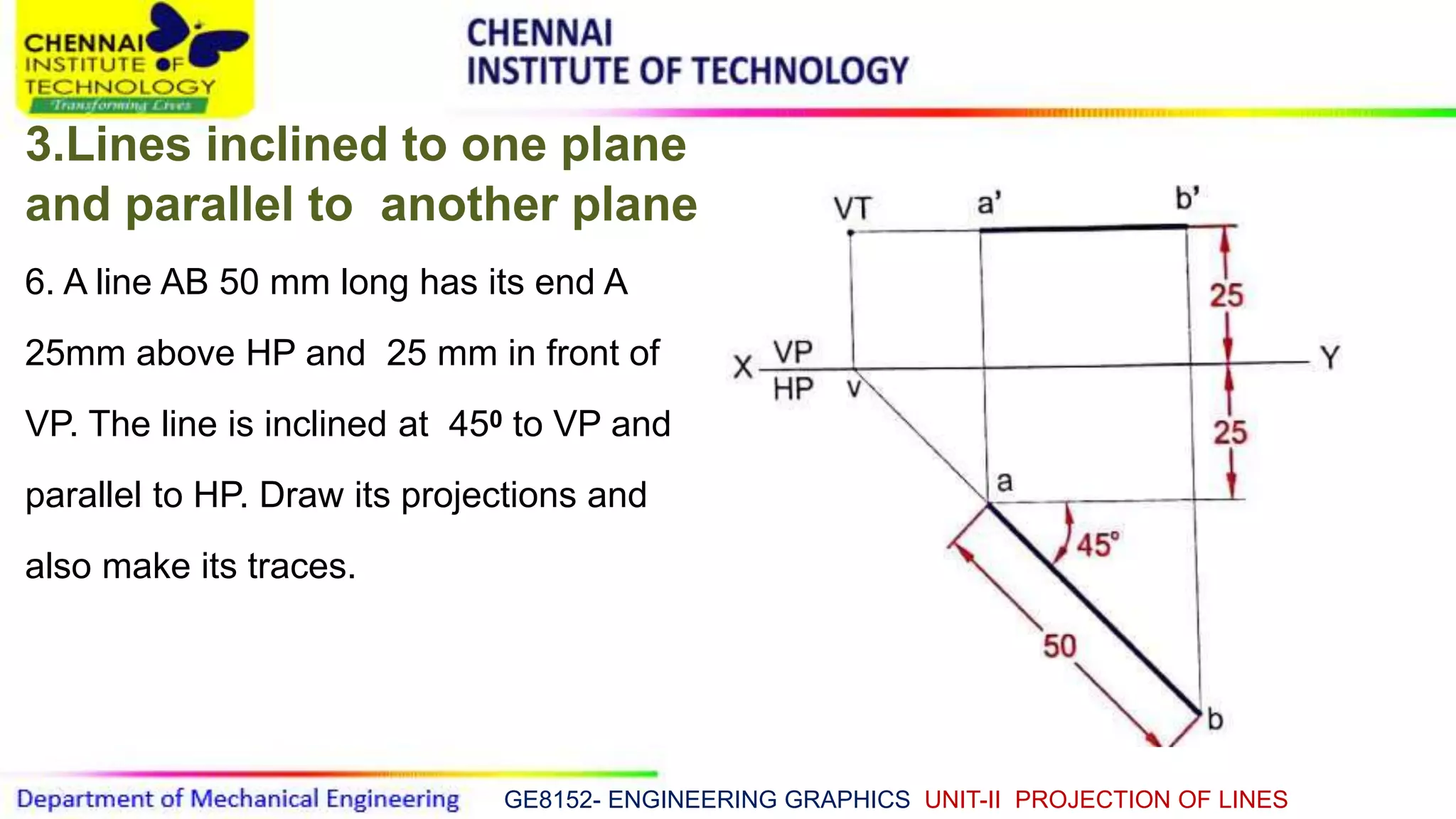
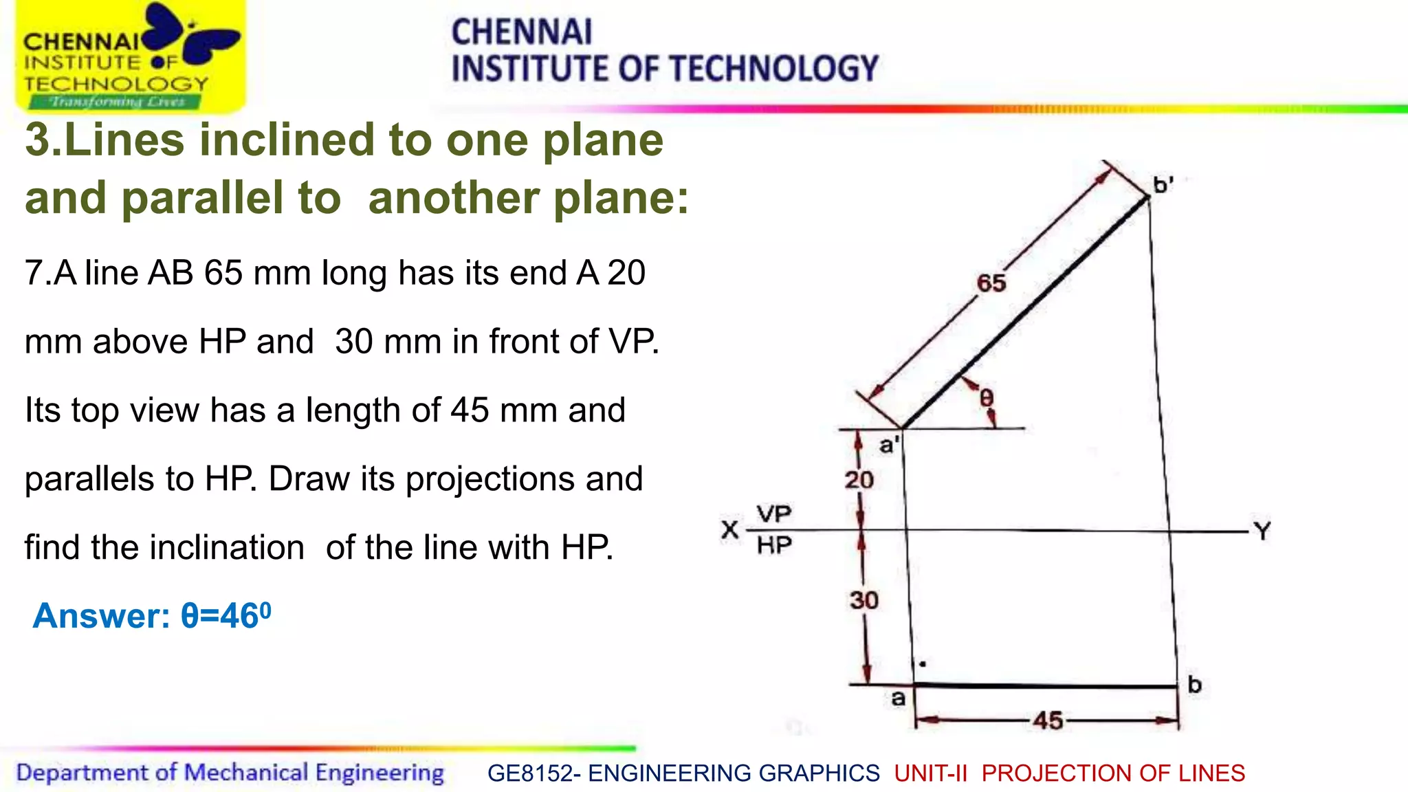
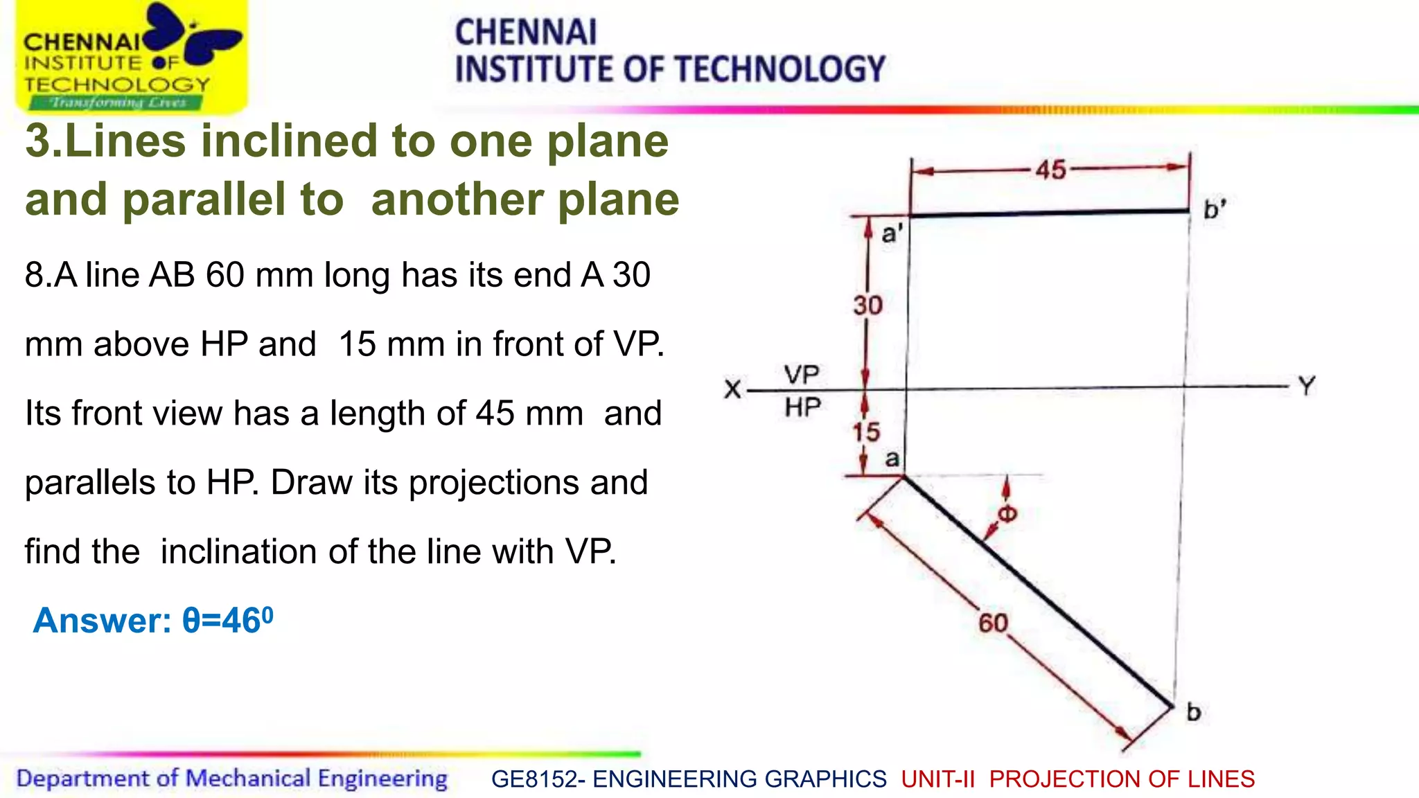
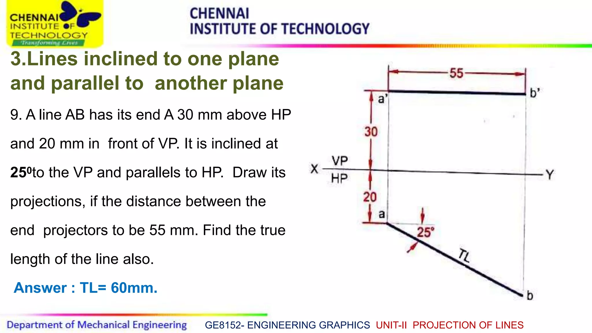
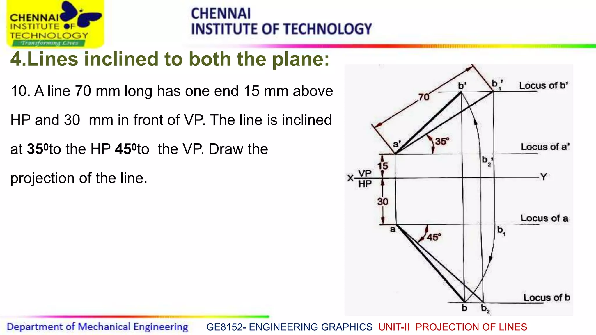
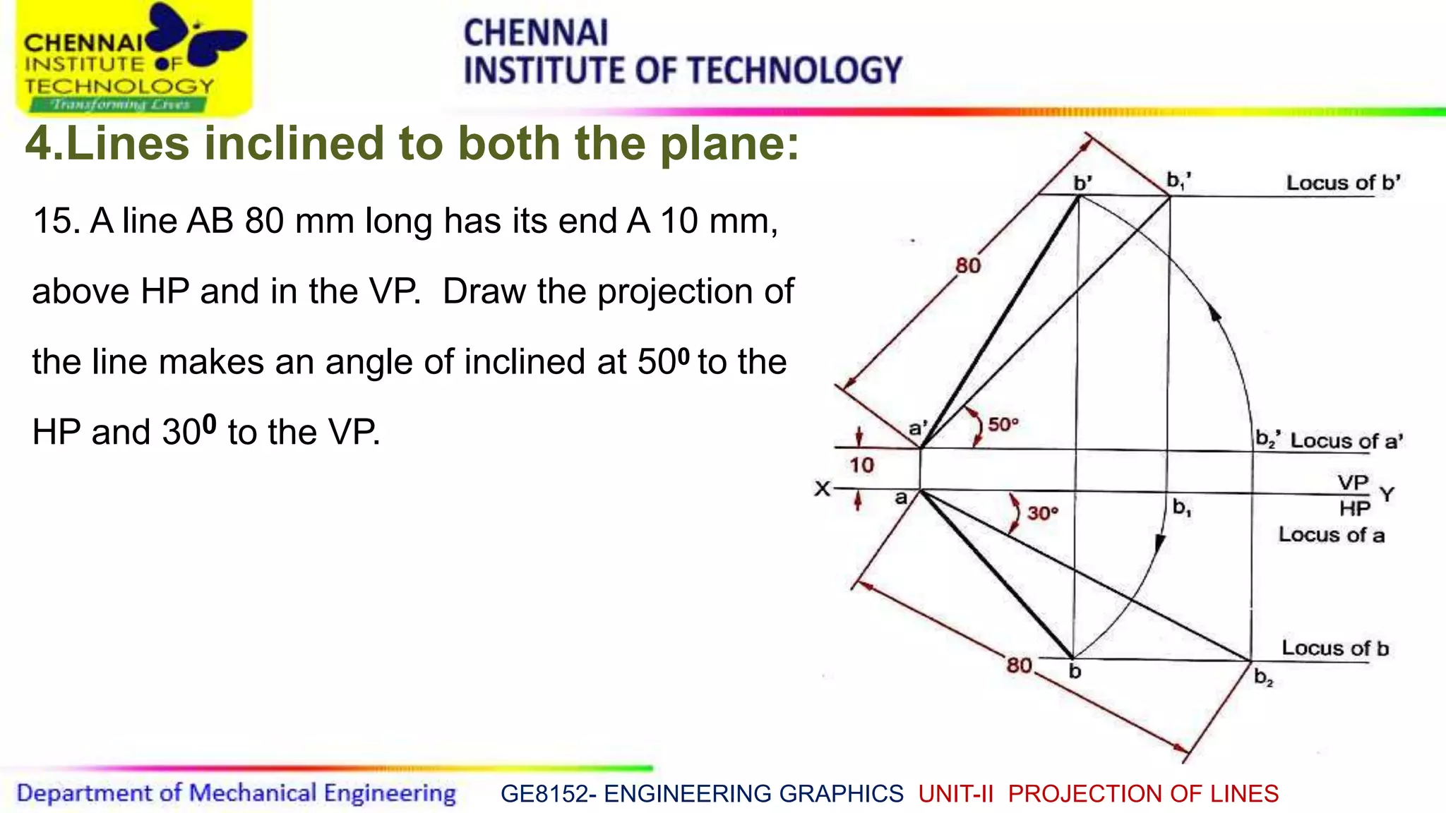
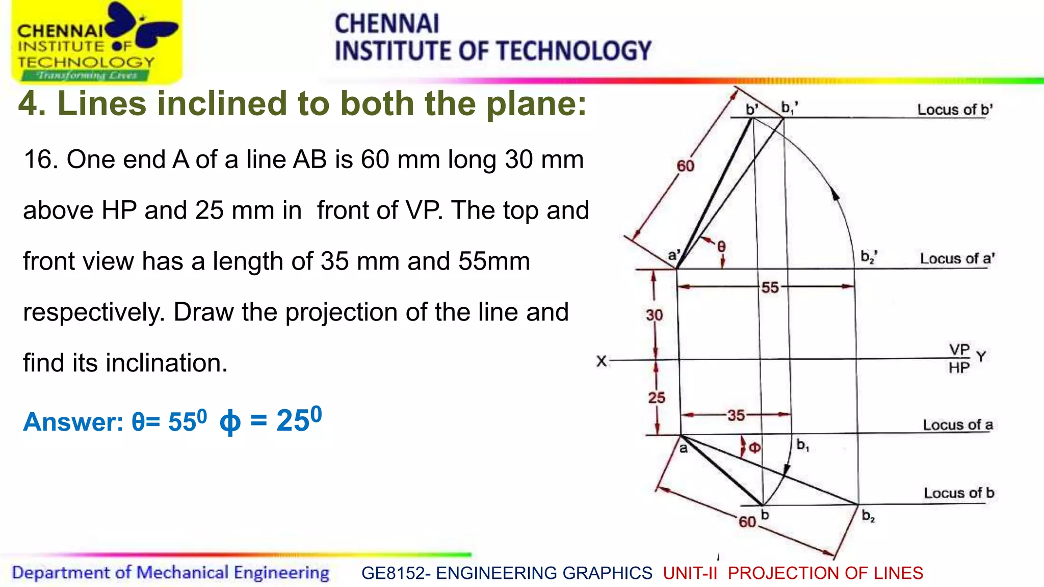
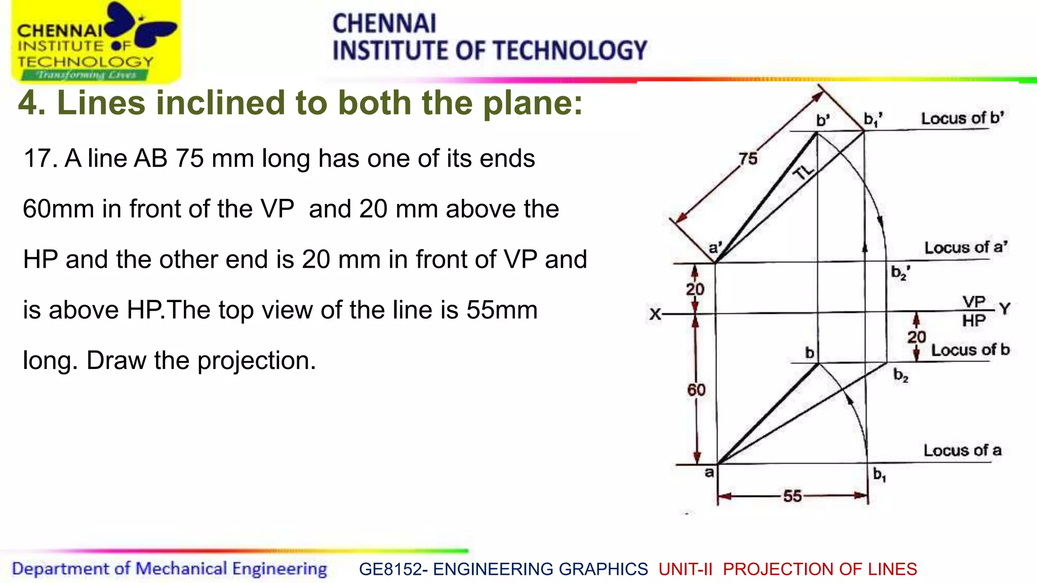
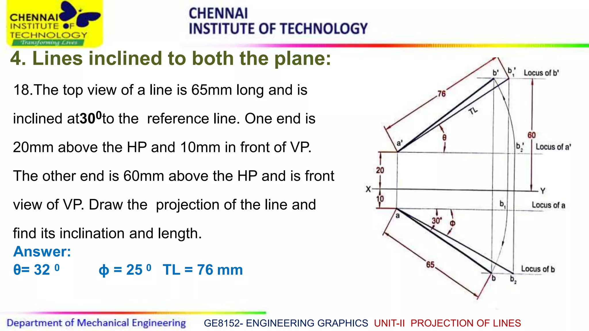
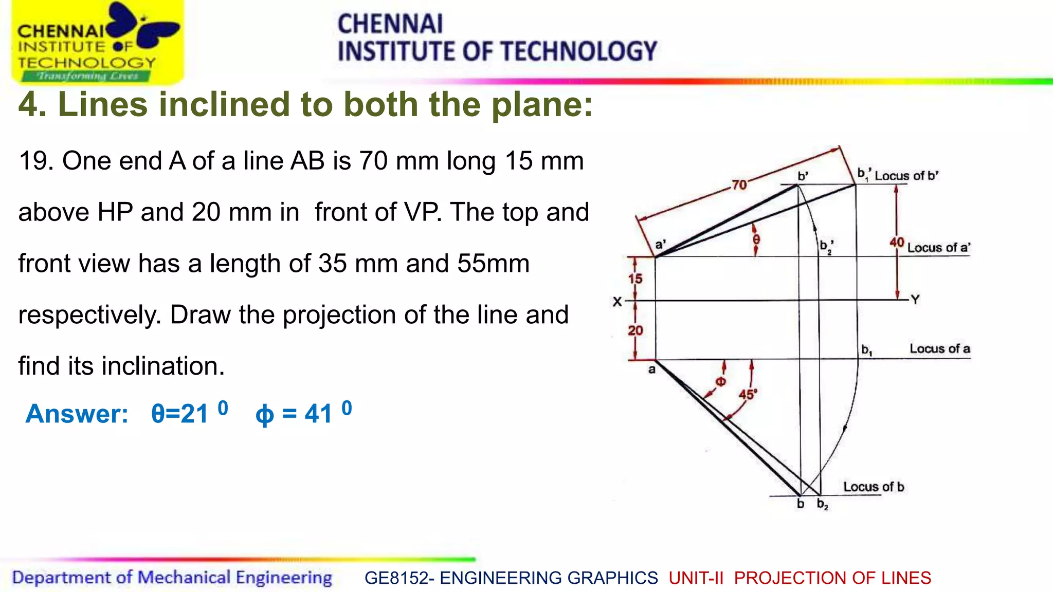
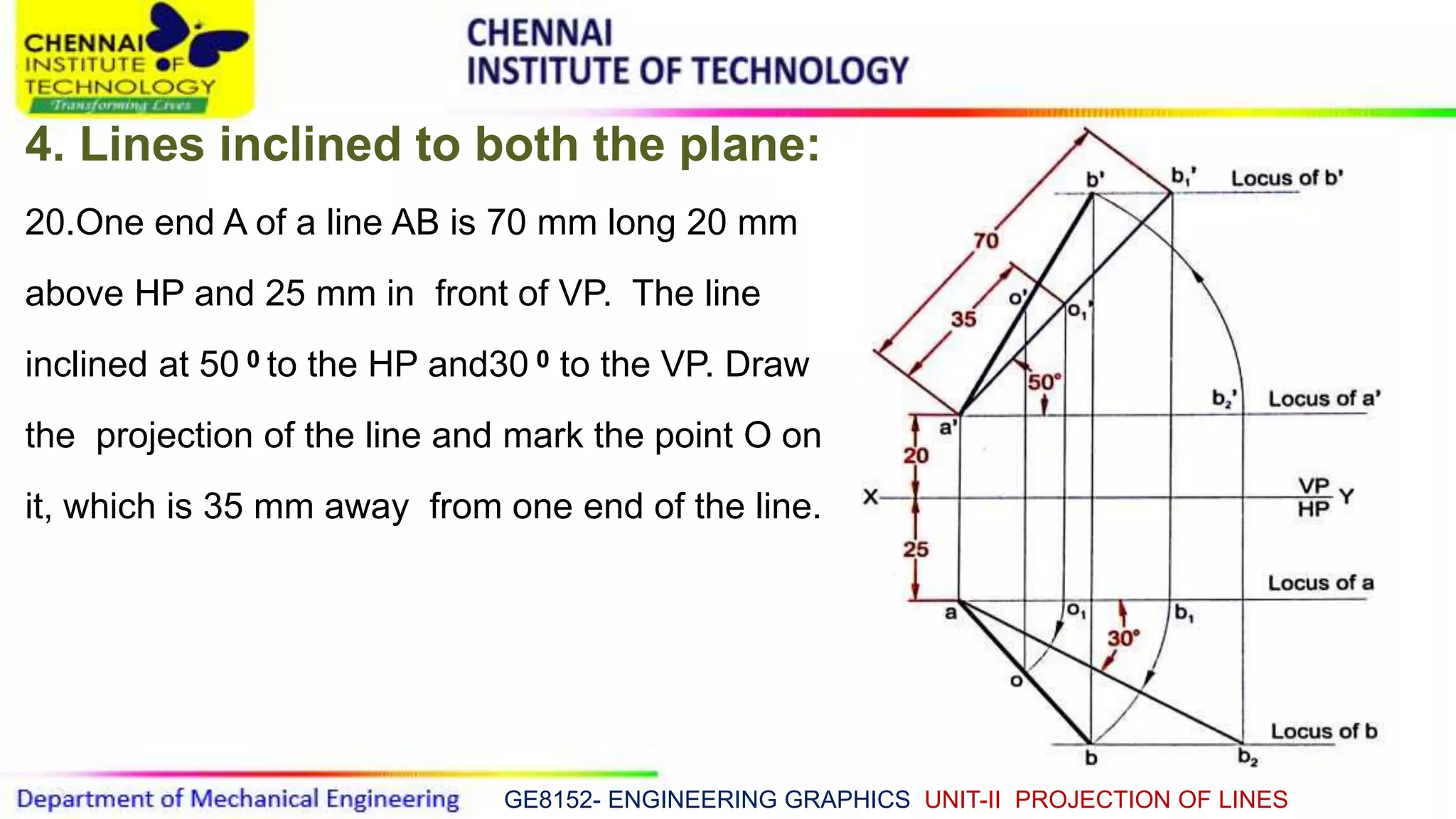
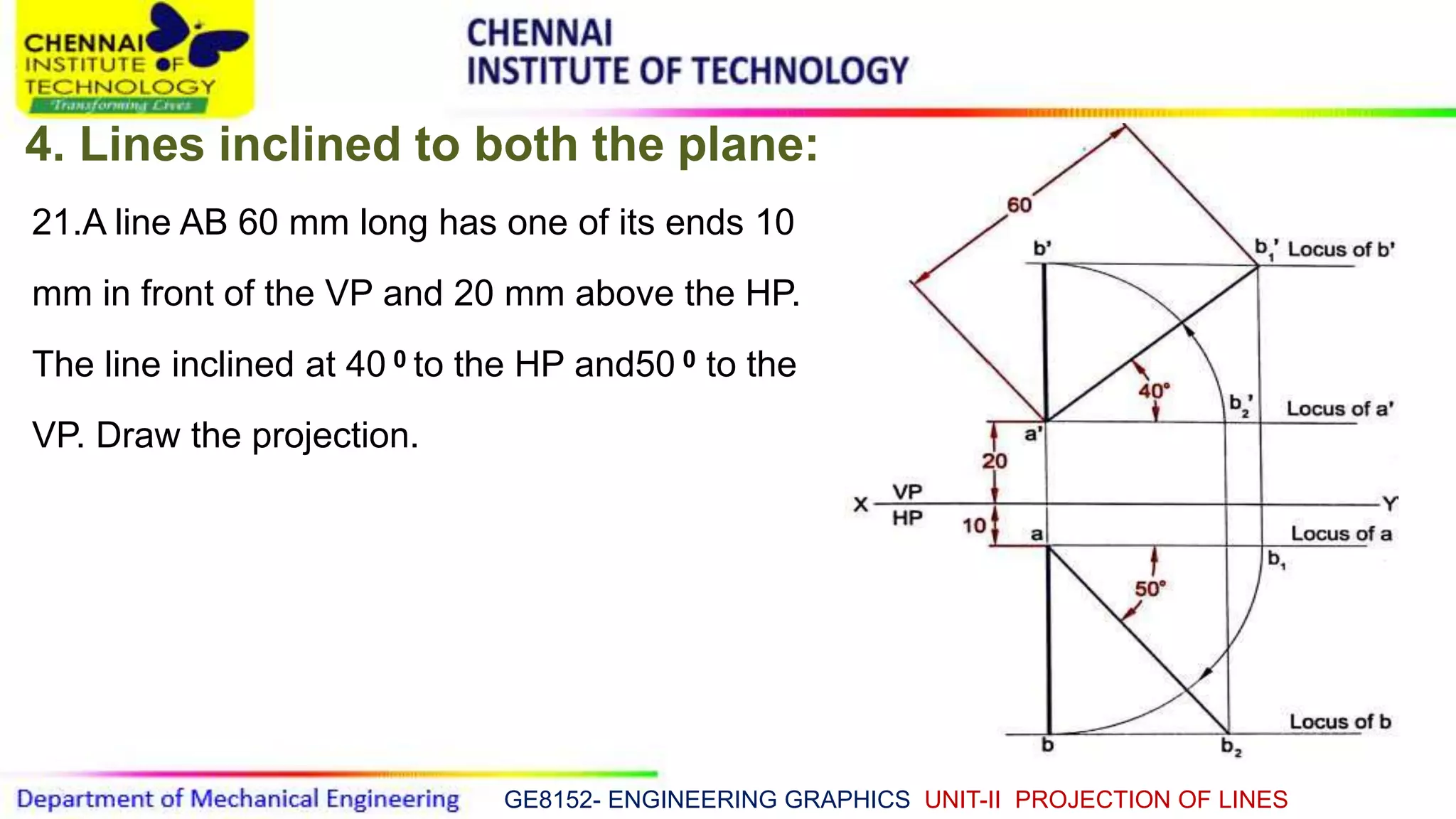
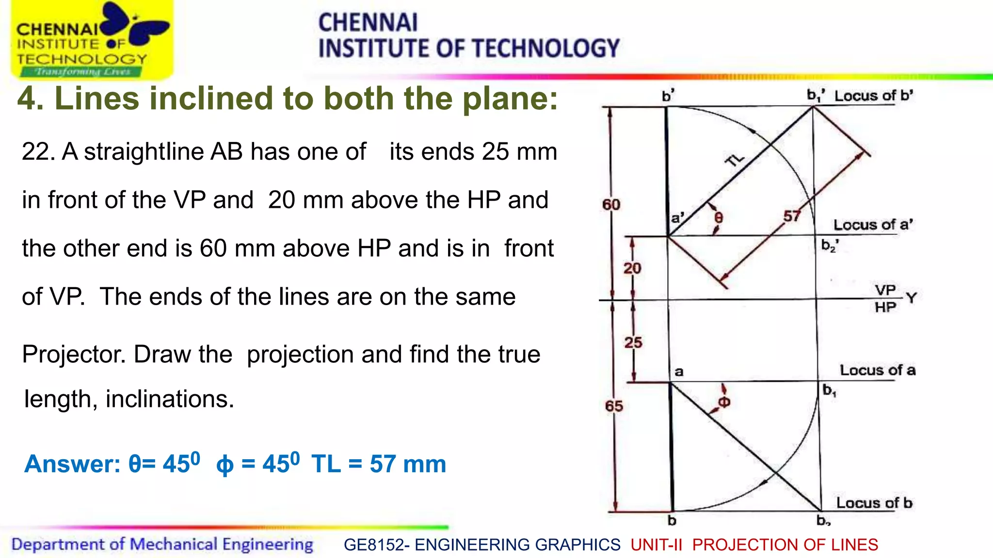
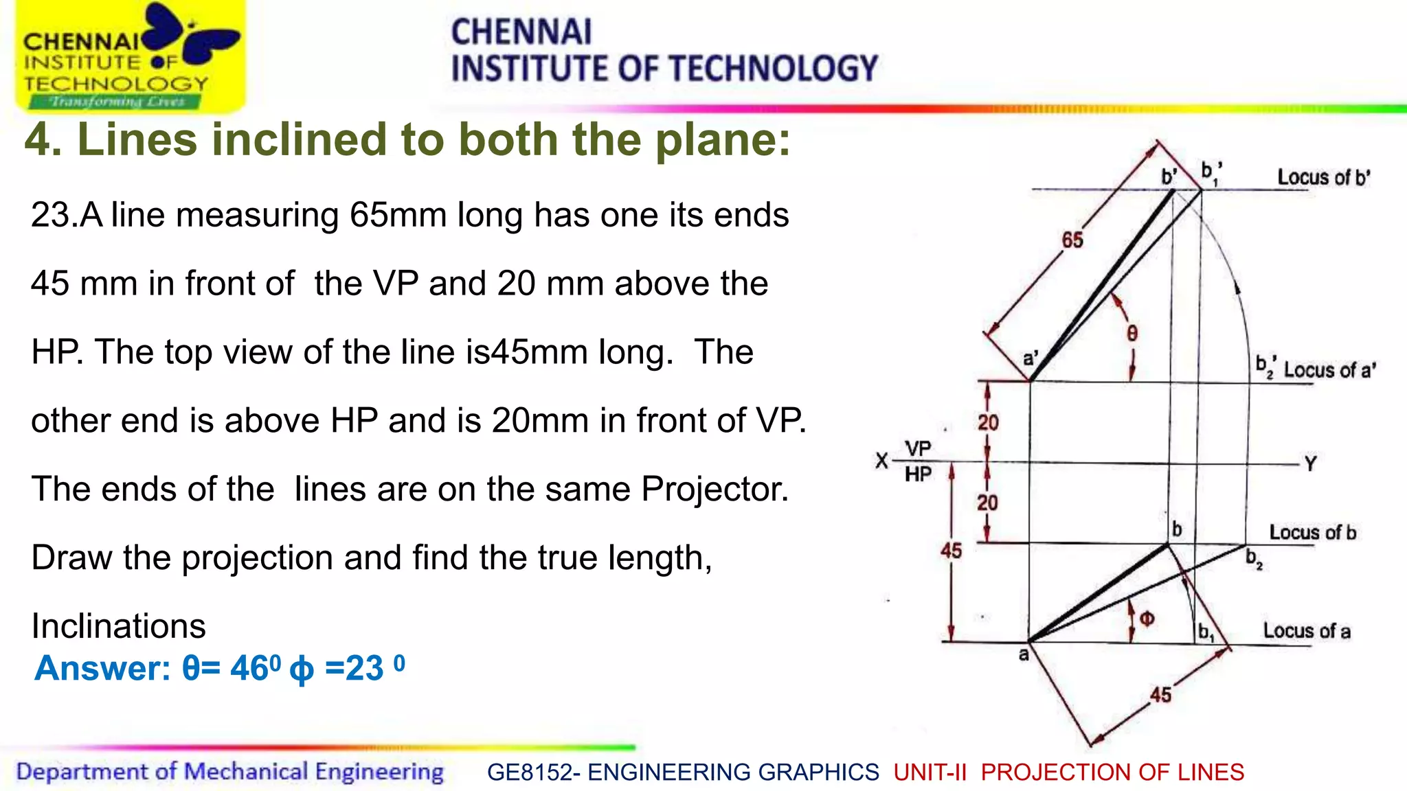
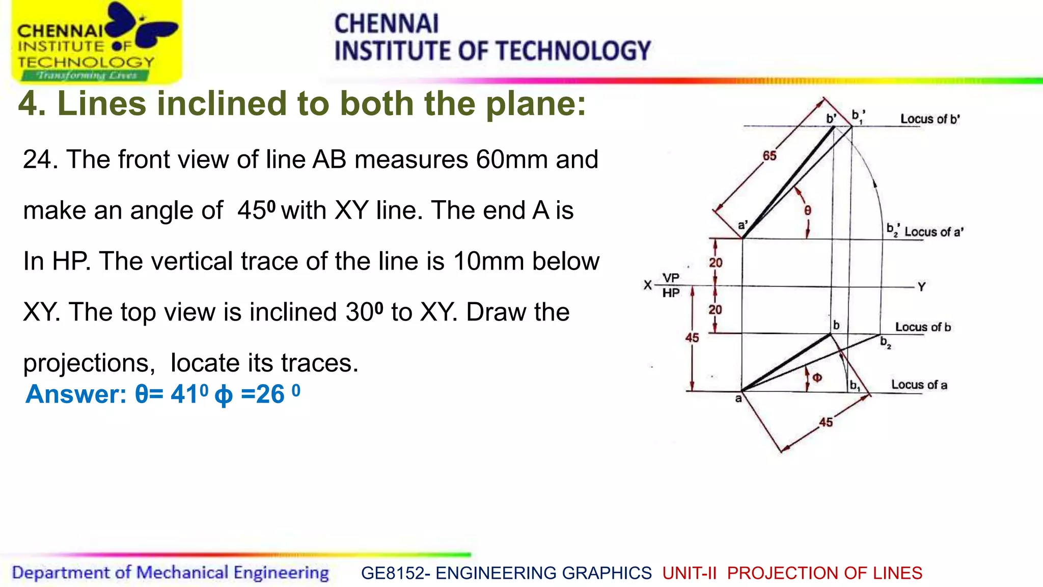
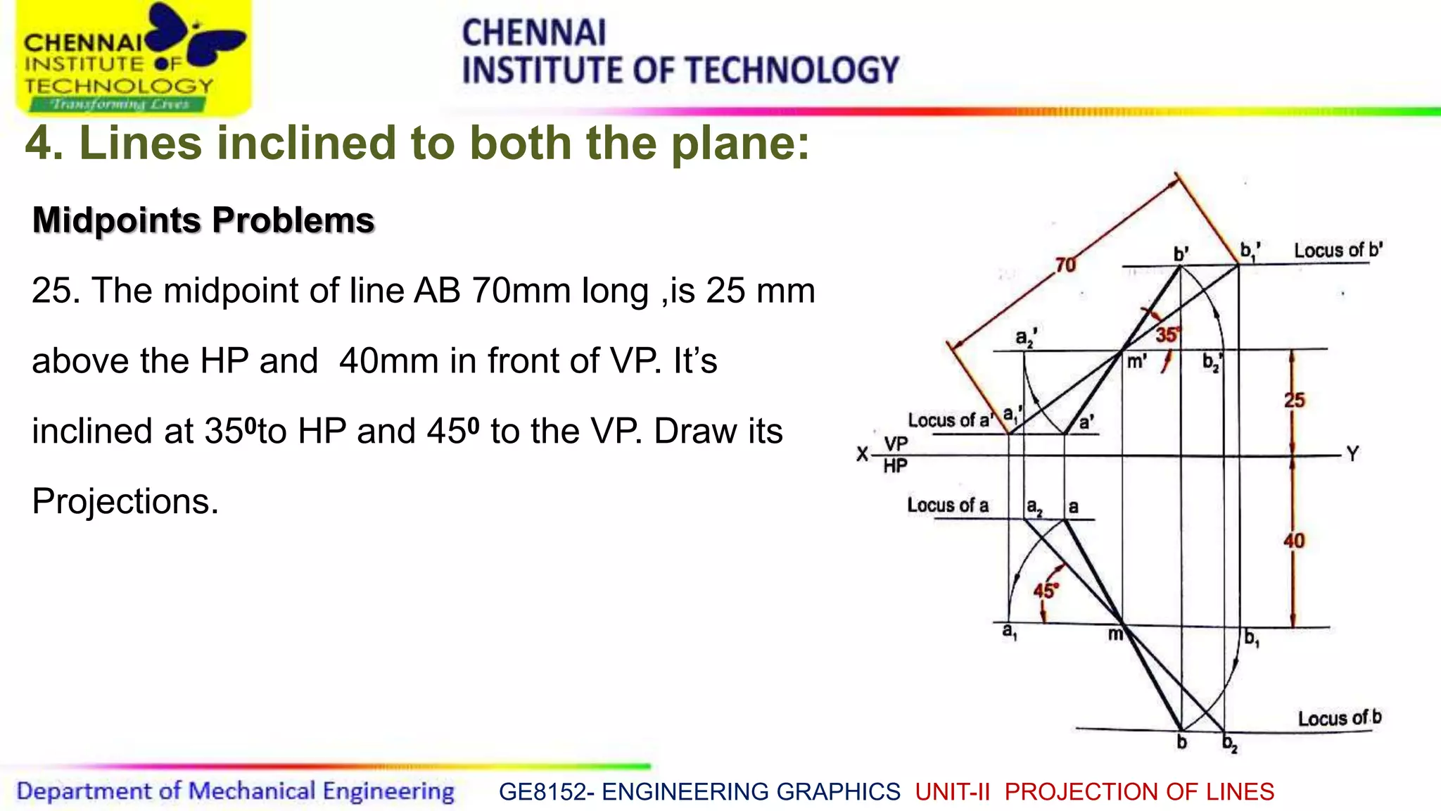
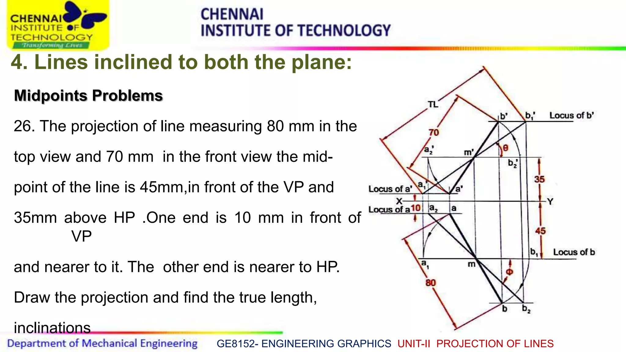
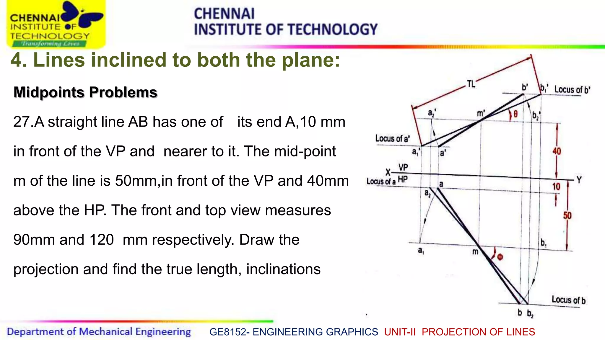
GE 8152 - ENGINEERING GRAPHICS
Dr.R.Ganesamoorthy.
Professor / Mechanical Engineering.
Chennai Institute of Technology.
GE8152- ENGINEERING GRAPHICS UNIT-II PROJECTION OF LINES
UNIT-II PROJECTION OF LINES
Object Line
It’s top view a, b
It’s front view a’, b’
It’s side view a’’, b’’
GE8152- ENGINEERING GRAPHICS UNIT-II PROJECTION OF LINES
The shortest distance between any two points is called a "straight line".
Different surfaces and planes form the configuration or shape of any object.
Thus a straight line is the basic conceptual figure using which any object like a
machine component or a structural element is represented.
Thus projection of a straight line is the foundation of Engineering Drawing.
We have studied the projections of given points, Joining the respective
projections of two points therefore gives the projection of the straight line
joining the two points
GE8152- ENGINEERING GRAPHICS UNIT-II PROJECTION OF LINES
Objectives- Projection of Lines:
 Define straight line.
 Draw the projections of a straight line located at different positions with respect to
the VP and the HP.
 Position of line are arranged in planes.
GE8152- ENGINEERING GRAPHICS UNIT-II PROJECTION OF LINES
Coordinate System:
GE8152- ENGINEERING GRAPHICS UNIT-II PROJECTION OF LINES
Orientation of Line in Space:
The position of straight line in space can be described following:
1.Lines parallel to VP and perpendicular to HP
2.Lines perpendicular to VP and parallel to HP
3.Lines parallel to both VP and HP
4.Lines parallel to VP and inclined to HP
5.Lines inclined to VP and parallel to HP
6.Lines inclined to both VP and HP
GE8152- ENGINEERING GRAPHICS UNIT-II PROJECTION OF LINES
Notations of Lines in views:
Following notations should be followed while naming different views
in projections.
Object Line
It’s top view a, b
It’s front view a’, b’
It’s side view a’’, b’’
GE8152- ENGINEERING GRAPHICS UNIT-II PROJECTION OF LINES
Projection of straight line on its various positions:
S. No Position of the line Front view Top view Traces
1
Lines parallel to both
VP and HP
True length and is
parallel to XY
True length and is
parallel to XY
NO
TRACES
2
Lines perpendicular
to VP and parallel to
HP
Point
True length and is
Perpendicular to XY
Only VT
No HT
3
Lines parallel to VP and
perpendicular to HP
True length and is
Perpendicular to XY
Point
Only HT
No VT
4
Lines parallel to HP
and inclined to VP
Shorter than true length
and is parallel to XY
Has true length and
true inclination
Only VT
No HT
5
Lines inclined to HP
and parallel to VP
Has true length and true
inclination
Shorter than true length and
is parallel to XY
Only HT
No VT
6
Lines inclined to both
VP and HP
Shorter than true length,
inclined to XY and angle is
not true inclination
Shorter than true
length, inclined to XY and
angle is not true inclination
Both HT
and VT
GE8152- ENGINEERING GRAPHICS UNIT-II PROJECTION OF LINES
1.Perpendicular to the HP and Parallel to the VP:
GE8152- ENGINEERING GRAPHICS UNIT-II PROJECTION OF LINES
2.Perpendicular to the VP and Parallel to the HP:
GE8152- ENGINEERING GRAPHICS UNIT-II PROJECTION OF LINES
3.The line both parallel VP and HP:
GE8152- ENGINEERING GRAPHICS UNIT-II PROJECTION OF LINES
4.Parallel to the HP and Inclined to the VP:
GE8152- ENGINEERING GRAPHICS UNIT-II PROJECTION OF LINES
5.Parallel to the VP and Inclined to the HP:
GE8152- ENGINEERING GRAPHICS UNIT-II PROJECTION OF LINES
6.The line both inclined VP and HP:
GE8152- ENGINEERING GRAPHICS UNIT-II PROJECTION OF LINES
6.The line both inclined VP and HP:
GE8152- ENGINEERING GRAPHICS UNIT-II PROJECTION OF LINES
1.Lines parallel to both VP and HP
1.A line CD 50mm long has its end C, 15mm above the HP and 25 mm in front of the
VP . The line is kept parallel to both HP and VP .draw its projections.
GE8152- ENGINEERING GRAPHICS UNIT-II PROJECTION OF LINES
2. Lines perpendicular to one plane
and parallel to another plane
2.A line 55 mm long has its end E 15 mm above
the HP and 25 mm in front of the VP. The line is
kept perpendicular to HP and parallel to VP. Draw
its projections.
GE8152- ENGINEERING GRAPHICS UNIT-II PROJECTION OF LINES
2.Lines perpendicular to one plane
and parallel to another plane
3.A line GH 50 mm long has its end G 20 mm
above the HP and 25 mm in front of the VP. The
line is kept perpendicular to VP and parallel to
HP. Draw its projections.
GE8152- ENGINEERING GRAPHICS UNIT-II PROJECTION OF LINES
3.Lines inclined to one plane
and parallel to another plane
4.A line AB 55 mm long is lying on the HP and
makes an angle of 350 with the VP. Its end A
is 25mm in front of VP. Draw the projections
of the line .
GE8152- ENGINEERING GRAPHICS UNIT-II PROJECTION OF LINES
3.Lines inclined to one plane and
parallel to another plane
5. A line AB 50 mm long has its end A 30mm
above HP and 25 mm in front of VP. The line
is kept inclined at 400 to HP and parallel to VP.
Draw its projections and make its traces.
GE8152- ENGINEERING GRAPHICS UNIT-II PROJECTION OF LINES
3.Lines inclined to one plane
and parallel to another plane
6. A line AB 50 mm long has its end A
25mm above HP and 25 mm in front of
VP. The line is inclined at 450 to VP and
parallel to HP. Draw its projections and
also make its traces.
GE8152- ENGINEERING GRAPHICS UNIT-II PROJECTION OF LINES
3.Lines inclined to one plane
and parallel to another plane:
7.A line AB 65 mm long has its end A 20
mm above HP and 30 mm in front of VP.
Its top view has a length of 45 mm and
parallels to HP. Draw its projections and
find the inclination of the line with HP.
Answer: θ=460
GE8152- ENGINEERING GRAPHICS UNIT-II PROJECTION OF LINES
3.Lines inclined to one plane
and parallel to another plane
8.A line AB 60 mm long has its end A 30
mm above HP and 15 mm in front of VP.
Its front view has a length of 45 mm and
parallels to HP. Draw its projections and
find the inclination of the line with VP.
Answer: θ=460
GE8152- ENGINEERING GRAPHICS UNIT-II PROJECTION OF LINES
3.Lines inclined to one plane
and parallel to another plane
9. A line AB has its end A 30 mm above HP
and 20 mm in front of VP. It is inclined at
250to the VP and parallels to HP. Draw its
projections, if the distance between the
end projectors to be 55 mm. Find the true
length of the line also.
Answer : TL= 60mm.
GE8152- ENGINEERING GRAPHICS UNIT-II PROJECTION OF LINES
4.Lines inclined to both the plane:
10. A line 70 mm long has one end 15 mm above
HP and 30 mm in front of VP. The line is inclined
at 350to the HP 450to the VP. Draw the
projection of the line.
GE8152- ENGINEERING GRAPHICS UNIT-II PROJECTION OF LINES
4.Lines inclined to both the plane:
11. One end of a line AB 70 mm long, is 10 mm
above HP and 25 mm in front of VP. The line is
inclined at 250 to the HP 450 to the VP. Draw the
projections and find its traces.
GE8152- ENGINEERING GRAPHICS UNIT-II PROJECTION OF LINES
4. Lines inclined to both the plane:
12. A line AB 75 mm long has one end A 20 mm
above HP and 25 mm in front of VP. The end B
is 50mm above the HP and 60 mm in front of VP.
Draw the projection of the line and find its
inclination with HP and VP.
Answer: θ= 24 0ϕ = 28 0
GE8152- ENGINEERING GRAPHICS UNIT-II PROJECTION OF LINES
4.Lines inclined to both the plane:
13.One end of a line AB is 10 mm above HP and
20 mm in front of VP. The other end is 45 mm
above HP and 65 mm in front of VP the distance
between the end projector is 40mm. Draw the
projection of the line and find its inclination and
length.
Answer : θ= 30 0 ϕ = 40 0 TL = 70 mm
GE8152- ENGINEERING GRAPHICS UNIT-II PROJECTION OF LINES
4. Lines inclined to both the plane:
14. A line AB 65 mm long in the front view has its
end A 20 mm above HP and 15 mm in front of
VP. The end B is 45 mm in front of VP. Draw the
projection of the line and find its inclination with
HP and VP. The distance between the ends
projectors passing through the end point is 50
mm. Draw the projection of the line and find its
Inclination.Answer: θ= 35 0 ϕ = 25 0 TL = 71 mm
GE8152- ENGINEERING GRAPHICS UNIT-II PROJECTION OF LINES
4.Lines inclined to both the plane:
15. A line AB 80 mm long has its end A 10 mm,
above HP and in the VP. Draw the projection of
the line makes an angle of inclined at 500 to the
HP and 300 to the VP.
GE8152- ENGINEERING GRAPHICS UNIT-II PROJECTION OF LINES
4. Lines inclined to both the plane:
16. One end A of a line AB is 60 mm long 30 mm
above HP and 25 mm in front of VP. The top and
front view has a length of 35 mm and 55mm
respectively. Draw the projection of the line and
find its inclination.
Answer: θ= 550 ϕ = 250
GE8152- ENGINEERING GRAPHICS UNIT-II PROJECTION OF LINES
4. Lines inclined to both the plane:
17. A line AB 75 mm long has one of its ends
60mm in front of the VP and 20 mm above the
HP and the other end is 20 mm in front of VP and
is above HP.The top view of the line is 55mm
long. Draw the projection.
GE8152- ENGINEERING GRAPHICS UNIT-II PROJECTION OF LINES
4. Lines inclined to both the plane:
18.The top view of a line is 65mm long and is
inclined at300to the reference line. One end is
20mm above the HP and 10mm in front of VP.
The other end is 60mm above the HP and is front
view of VP. Draw the projection of the line and
find its inclination and length.
Answer:
θ= 32 0 ϕ = 25 0 TL = 76 mm
GE8152- ENGINEERING GRAPHICS UNIT-II PROJECTION OF LINES
4. Lines inclined to both the plane:
19. One end A of a line AB is 70 mm long 15 mm
above HP and 20 mm in front of VP. The top and
front view has a length of 35 mm and 55mm
respectively. Draw the projection of the line and
find its inclination.
Answer: θ=21 0 ϕ = 41 0
GE8152- ENGINEERING GRAPHICS UNIT-II PROJECTION OF LINES
4. Lines inclined to both the plane:
20.One end A of a line AB is 70 mm long 20 mm
above HP and 25 mm in front of VP. The line
inclined at 50 0 to the HP and30 0 to the VP. Draw
the projection of the line and mark the point O on
it, which is 35 mm away from one end of the line.
GE8152- ENGINEERING GRAPHICS UNIT-II PROJECTION OF LINES
4. Lines inclined to both the plane:
21.A line AB 60 mm long has one of its ends 10
mm in front of the VP and 20 mm above the HP.
The line inclined at 40 0 to the HP and50 0 to the
VP. Draw the projection.
GE8152- ENGINEERING GRAPHICS UNIT-II PROJECTION OF LINES
4. Lines inclined to both the plane:
22. A straightline AB has one of its ends 25 mm
in front of the VP and 20 mm above the HP and
the other end is 60 mm above HP and is in front
of VP. The ends of the lines are on the same
Projector. Draw the projection and find the true
length, inclinations.
Answer: θ= 450 ϕ = 450 TL = 57 mm
GE8152- ENGINEERING GRAPHICS UNIT-II PROJECTION OF LINES
4. Lines inclined to both the plane:
23.A line measuring 65mm long has one its ends
45 mm in front of the VP and 20 mm above the
HP. The top view of the line is45mm long. The
other end is above HP and is 20mm in front of VP.
The ends of the lines are on the same Projector.
Draw the projection and find the true length,
Inclinations
Answer: θ= 460 ϕ =23 0
GE8152- ENGINEERING GRAPHICS UNIT-II PROJECTION OF LINES
4. Lines inclined to both the plane:
24. The front view of line AB measures 60mm and
make an angle of 450 with XY line. The end A is
In HP. The vertical trace of the line is 10mm below
XY. The top view is inclined 300 to XY. Draw the
projections, locate its traces.
Answer: θ= 410 ϕ =26 0
GE8152- ENGINEERING GRAPHICS UNIT-II PROJECTION OF LINES
4. Lines inclined to both the plane:
Midpoints Problems
25. The midpoint of line AB 70mm long ,is 25 mm
above the HP and 40mm in front of VP. It’s
inclined at 350to HP and 450 to the VP. Draw its
Projections.
GE8152- ENGINEERING GRAPHICS UNIT-II PROJECTION OF LINES
4. Lines inclined to both the plane:
Midpoints Problems
26. The projection of line measuring 80 mm in the
top view and 70 mm in the front view the mid-
point of the line is 45mm,in front of the VP and
35mm above HP .One end is 10 mm in front of
VP
and nearer to it. The other end is nearer to HP.
Draw the projection and find the true length,
inclinations
GE8152- ENGINEERING GRAPHICS UNIT-II PROJECTION OF LINES
4. Lines inclined to both the plane:
Midpoints Problems
27.A straight line AB has one of its end A,10 mm
in front of the VP and nearer to it. The mid-point
m of the line is 50mm,in front of the VP and 40mm
above the HP. The front and top view measures
90mm and 120 mm respectively. Draw the
projection and find the true length, inclinations
GE8152- ENGINEERING GRAPHICS - UNIT-II PROJECTION OF LINES
Thank you

EG UNIT-II PROJECTION OF LINES.ppt

  • 1.
    GE 8152 -ENGINEERING GRAPHICS Dr.R.Ganesamoorthy. Professor / Mechanical Engineering. Chennai Institute of Technology. GE8152- ENGINEERING GRAPHICS UNIT-II PROJECTION OF LINES UNIT-II PROJECTION OF LINES Object Line It’s top view a, b It’s front view a’, b’ It’s side view a’’, b’’
  • 2.
    GE8152- ENGINEERING GRAPHICSUNIT-II PROJECTION OF LINES The shortest distance between any two points is called a "straight line". Different surfaces and planes form the configuration or shape of any object. Thus a straight line is the basic conceptual figure using which any object like a machine component or a structural element is represented. Thus projection of a straight line is the foundation of Engineering Drawing. We have studied the projections of given points, Joining the respective projections of two points therefore gives the projection of the straight line joining the two points
  • 3.
    GE8152- ENGINEERING GRAPHICSUNIT-II PROJECTION OF LINES Objectives- Projection of Lines:  Define straight line.  Draw the projections of a straight line located at different positions with respect to the VP and the HP.  Position of line are arranged in planes.
  • 4.
    GE8152- ENGINEERING GRAPHICSUNIT-II PROJECTION OF LINES Coordinate System:
  • 5.
    GE8152- ENGINEERING GRAPHICSUNIT-II PROJECTION OF LINES Orientation of Line in Space: The position of straight line in space can be described following: 1.Lines parallel to VP and perpendicular to HP 2.Lines perpendicular to VP and parallel to HP 3.Lines parallel to both VP and HP 4.Lines parallel to VP and inclined to HP 5.Lines inclined to VP and parallel to HP 6.Lines inclined to both VP and HP
  • 6.
    GE8152- ENGINEERING GRAPHICSUNIT-II PROJECTION OF LINES Notations of Lines in views: Following notations should be followed while naming different views in projections. Object Line It’s top view a, b It’s front view a’, b’ It’s side view a’’, b’’
  • 7.
    GE8152- ENGINEERING GRAPHICSUNIT-II PROJECTION OF LINES Projection of straight line on its various positions: S. No Position of the line Front view Top view Traces 1 Lines parallel to both VP and HP True length and is parallel to XY True length and is parallel to XY NO TRACES 2 Lines perpendicular to VP and parallel to HP Point True length and is Perpendicular to XY Only VT No HT 3 Lines parallel to VP and perpendicular to HP True length and is Perpendicular to XY Point Only HT No VT 4 Lines parallel to HP and inclined to VP Shorter than true length and is parallel to XY Has true length and true inclination Only VT No HT 5 Lines inclined to HP and parallel to VP Has true length and true inclination Shorter than true length and is parallel to XY Only HT No VT 6 Lines inclined to both VP and HP Shorter than true length, inclined to XY and angle is not true inclination Shorter than true length, inclined to XY and angle is not true inclination Both HT and VT
  • 8.
    GE8152- ENGINEERING GRAPHICSUNIT-II PROJECTION OF LINES 1.Perpendicular to the HP and Parallel to the VP:
  • 9.
    GE8152- ENGINEERING GRAPHICSUNIT-II PROJECTION OF LINES 2.Perpendicular to the VP and Parallel to the HP:
  • 10.
    GE8152- ENGINEERING GRAPHICSUNIT-II PROJECTION OF LINES 3.The line both parallel VP and HP:
  • 11.
    GE8152- ENGINEERING GRAPHICSUNIT-II PROJECTION OF LINES 4.Parallel to the HP and Inclined to the VP:
  • 12.
    GE8152- ENGINEERING GRAPHICSUNIT-II PROJECTION OF LINES 5.Parallel to the VP and Inclined to the HP:
  • 13.
    GE8152- ENGINEERING GRAPHICSUNIT-II PROJECTION OF LINES 6.The line both inclined VP and HP:
  • 14.
    GE8152- ENGINEERING GRAPHICSUNIT-II PROJECTION OF LINES 6.The line both inclined VP and HP:
  • 15.
    GE8152- ENGINEERING GRAPHICSUNIT-II PROJECTION OF LINES 1.Lines parallel to both VP and HP 1.A line CD 50mm long has its end C, 15mm above the HP and 25 mm in front of the VP . The line is kept parallel to both HP and VP .draw its projections.
  • 16.
    GE8152- ENGINEERING GRAPHICSUNIT-II PROJECTION OF LINES 2. Lines perpendicular to one plane and parallel to another plane 2.A line 55 mm long has its end E 15 mm above the HP and 25 mm in front of the VP. The line is kept perpendicular to HP and parallel to VP. Draw its projections.
  • 17.
    GE8152- ENGINEERING GRAPHICSUNIT-II PROJECTION OF LINES 2.Lines perpendicular to one plane and parallel to another plane 3.A line GH 50 mm long has its end G 20 mm above the HP and 25 mm in front of the VP. The line is kept perpendicular to VP and parallel to HP. Draw its projections.
  • 18.
    GE8152- ENGINEERING GRAPHICSUNIT-II PROJECTION OF LINES 3.Lines inclined to one plane and parallel to another plane 4.A line AB 55 mm long is lying on the HP and makes an angle of 350 with the VP. Its end A is 25mm in front of VP. Draw the projections of the line .
  • 19.
    GE8152- ENGINEERING GRAPHICSUNIT-II PROJECTION OF LINES 3.Lines inclined to one plane and parallel to another plane 5. A line AB 50 mm long has its end A 30mm above HP and 25 mm in front of VP. The line is kept inclined at 400 to HP and parallel to VP. Draw its projections and make its traces.
  • 20.
    GE8152- ENGINEERING GRAPHICSUNIT-II PROJECTION OF LINES 3.Lines inclined to one plane and parallel to another plane 6. A line AB 50 mm long has its end A 25mm above HP and 25 mm in front of VP. The line is inclined at 450 to VP and parallel to HP. Draw its projections and also make its traces.
  • 21.
    GE8152- ENGINEERING GRAPHICSUNIT-II PROJECTION OF LINES 3.Lines inclined to one plane and parallel to another plane: 7.A line AB 65 mm long has its end A 20 mm above HP and 30 mm in front of VP. Its top view has a length of 45 mm and parallels to HP. Draw its projections and find the inclination of the line with HP. Answer: θ=460
  • 22.
    GE8152- ENGINEERING GRAPHICSUNIT-II PROJECTION OF LINES 3.Lines inclined to one plane and parallel to another plane 8.A line AB 60 mm long has its end A 30 mm above HP and 15 mm in front of VP. Its front view has a length of 45 mm and parallels to HP. Draw its projections and find the inclination of the line with VP. Answer: θ=460
  • 23.
    GE8152- ENGINEERING GRAPHICSUNIT-II PROJECTION OF LINES 3.Lines inclined to one plane and parallel to another plane 9. A line AB has its end A 30 mm above HP and 20 mm in front of VP. It is inclined at 250to the VP and parallels to HP. Draw its projections, if the distance between the end projectors to be 55 mm. Find the true length of the line also. Answer : TL= 60mm.
  • 24.
    GE8152- ENGINEERING GRAPHICSUNIT-II PROJECTION OF LINES 4.Lines inclined to both the plane: 10. A line 70 mm long has one end 15 mm above HP and 30 mm in front of VP. The line is inclined at 350to the HP 450to the VP. Draw the projection of the line.
  • 25.
    GE8152- ENGINEERING GRAPHICSUNIT-II PROJECTION OF LINES 4.Lines inclined to both the plane: 11. One end of a line AB 70 mm long, is 10 mm above HP and 25 mm in front of VP. The line is inclined at 250 to the HP 450 to the VP. Draw the projections and find its traces.
  • 26.
    GE8152- ENGINEERING GRAPHICSUNIT-II PROJECTION OF LINES 4. Lines inclined to both the plane: 12. A line AB 75 mm long has one end A 20 mm above HP and 25 mm in front of VP. The end B is 50mm above the HP and 60 mm in front of VP. Draw the projection of the line and find its inclination with HP and VP. Answer: θ= 24 0ϕ = 28 0
  • 27.
    GE8152- ENGINEERING GRAPHICSUNIT-II PROJECTION OF LINES 4.Lines inclined to both the plane: 13.One end of a line AB is 10 mm above HP and 20 mm in front of VP. The other end is 45 mm above HP and 65 mm in front of VP the distance between the end projector is 40mm. Draw the projection of the line and find its inclination and length. Answer : θ= 30 0 ϕ = 40 0 TL = 70 mm
  • 28.
    GE8152- ENGINEERING GRAPHICSUNIT-II PROJECTION OF LINES 4. Lines inclined to both the plane: 14. A line AB 65 mm long in the front view has its end A 20 mm above HP and 15 mm in front of VP. The end B is 45 mm in front of VP. Draw the projection of the line and find its inclination with HP and VP. The distance between the ends projectors passing through the end point is 50 mm. Draw the projection of the line and find its Inclination.Answer: θ= 35 0 ϕ = 25 0 TL = 71 mm
  • 29.
    GE8152- ENGINEERING GRAPHICSUNIT-II PROJECTION OF LINES 4.Lines inclined to both the plane: 15. A line AB 80 mm long has its end A 10 mm, above HP and in the VP. Draw the projection of the line makes an angle of inclined at 500 to the HP and 300 to the VP.
  • 30.
    GE8152- ENGINEERING GRAPHICSUNIT-II PROJECTION OF LINES 4. Lines inclined to both the plane: 16. One end A of a line AB is 60 mm long 30 mm above HP and 25 mm in front of VP. The top and front view has a length of 35 mm and 55mm respectively. Draw the projection of the line and find its inclination. Answer: θ= 550 ϕ = 250
  • 31.
    GE8152- ENGINEERING GRAPHICSUNIT-II PROJECTION OF LINES 4. Lines inclined to both the plane: 17. A line AB 75 mm long has one of its ends 60mm in front of the VP and 20 mm above the HP and the other end is 20 mm in front of VP and is above HP.The top view of the line is 55mm long. Draw the projection.
  • 32.
    GE8152- ENGINEERING GRAPHICSUNIT-II PROJECTION OF LINES 4. Lines inclined to both the plane: 18.The top view of a line is 65mm long and is inclined at300to the reference line. One end is 20mm above the HP and 10mm in front of VP. The other end is 60mm above the HP and is front view of VP. Draw the projection of the line and find its inclination and length. Answer: θ= 32 0 ϕ = 25 0 TL = 76 mm
  • 33.
    GE8152- ENGINEERING GRAPHICSUNIT-II PROJECTION OF LINES 4. Lines inclined to both the plane: 19. One end A of a line AB is 70 mm long 15 mm above HP and 20 mm in front of VP. The top and front view has a length of 35 mm and 55mm respectively. Draw the projection of the line and find its inclination. Answer: θ=21 0 ϕ = 41 0
  • 34.
    GE8152- ENGINEERING GRAPHICSUNIT-II PROJECTION OF LINES 4. Lines inclined to both the plane: 20.One end A of a line AB is 70 mm long 20 mm above HP and 25 mm in front of VP. The line inclined at 50 0 to the HP and30 0 to the VP. Draw the projection of the line and mark the point O on it, which is 35 mm away from one end of the line.
  • 35.
    GE8152- ENGINEERING GRAPHICSUNIT-II PROJECTION OF LINES 4. Lines inclined to both the plane: 21.A line AB 60 mm long has one of its ends 10 mm in front of the VP and 20 mm above the HP. The line inclined at 40 0 to the HP and50 0 to the VP. Draw the projection.
  • 36.
    GE8152- ENGINEERING GRAPHICSUNIT-II PROJECTION OF LINES 4. Lines inclined to both the plane: 22. A straightline AB has one of its ends 25 mm in front of the VP and 20 mm above the HP and the other end is 60 mm above HP and is in front of VP. The ends of the lines are on the same Projector. Draw the projection and find the true length, inclinations. Answer: θ= 450 ϕ = 450 TL = 57 mm
  • 37.
    GE8152- ENGINEERING GRAPHICSUNIT-II PROJECTION OF LINES 4. Lines inclined to both the plane: 23.A line measuring 65mm long has one its ends 45 mm in front of the VP and 20 mm above the HP. The top view of the line is45mm long. The other end is above HP and is 20mm in front of VP. The ends of the lines are on the same Projector. Draw the projection and find the true length, Inclinations Answer: θ= 460 ϕ =23 0
  • 38.
    GE8152- ENGINEERING GRAPHICSUNIT-II PROJECTION OF LINES 4. Lines inclined to both the plane: 24. The front view of line AB measures 60mm and make an angle of 450 with XY line. The end A is In HP. The vertical trace of the line is 10mm below XY. The top view is inclined 300 to XY. Draw the projections, locate its traces. Answer: θ= 410 ϕ =26 0
  • 39.
    GE8152- ENGINEERING GRAPHICSUNIT-II PROJECTION OF LINES 4. Lines inclined to both the plane: Midpoints Problems 25. The midpoint of line AB 70mm long ,is 25 mm above the HP and 40mm in front of VP. It’s inclined at 350to HP and 450 to the VP. Draw its Projections.
  • 40.
    GE8152- ENGINEERING GRAPHICSUNIT-II PROJECTION OF LINES 4. Lines inclined to both the plane: Midpoints Problems 26. The projection of line measuring 80 mm in the top view and 70 mm in the front view the mid- point of the line is 45mm,in front of the VP and 35mm above HP .One end is 10 mm in front of VP and nearer to it. The other end is nearer to HP. Draw the projection and find the true length, inclinations
  • 41.
    GE8152- ENGINEERING GRAPHICSUNIT-II PROJECTION OF LINES 4. Lines inclined to both the plane: Midpoints Problems 27.A straight line AB has one of its end A,10 mm in front of the VP and nearer to it. The mid-point m of the line is 50mm,in front of the VP and 40mm above the HP. The front and top view measures 90mm and 120 mm respectively. Draw the projection and find the true length, inclinations
  • 42.
    GE8152- ENGINEERING GRAPHICS- UNIT-II PROJECTION OF LINES Thank you