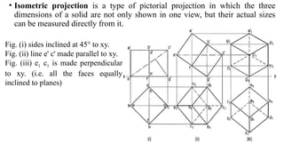
• Isometric projectionis a type of pictorial projection in which the three
dimensions of a solid are not only shown in one view, but their actual sizes
can be measured directly from it.
Fig. (i) sides inclined at 45° to xy.
Fig. (ii) line e' c' made parallel to xy.
Fig. (iii) e1 c1 is made perpendicular
to xy. (i.e. all the faces equally
inclined to planes)
5.
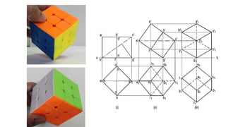
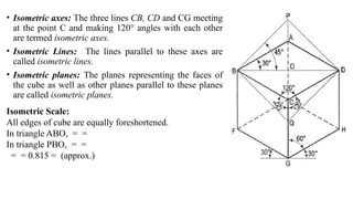
• Isometric axes:The three lines CB, CD and CG meeting
at the point C and making 120° angles with each other
are termed isometric axes.
• Isometric Lines: The lines parallel to these axes are
called isometric lines.
• Isometric planes: The planes representing the faces of
the cube as well as other planes parallel to these planes
are called isometric planes.
Isometric Scale:
All edges of cube are equally foreshortened.
In triangle ABO, = =
In triangle PBO, = =
= = 0.815 = (approx.)
6.
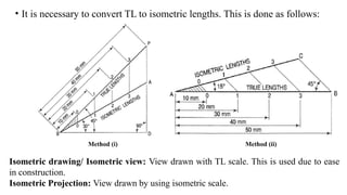
• It isnecessary to convert TL to isometric lengths. This is done as follows:
Method (i) Method (ii)
Isometric drawing/ Isometric view: View drawn with TL scale. This is used due to ease
in construction.
Isometric Projection: View drawn by using isometric scale.
7.
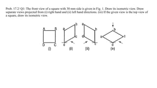
Prob. 17.2/ Q1:The front view of a square with 30 mm side is given in Fig. 1. Draw its isometric view. Draw
separate views projected from (i) right hand and (ii) left hand directions. (iii) If the given view is the top view of
a square, draw its isometric view.
8.
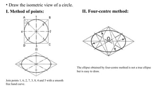
• Draw theisometric view of a circle.
I. Method of points: II. Four-centre method:
Join points 1, 6, 2, 7, 3, 8, 4 and 5 with a smooth
free hand curve.
The ellipse obtained by four-centre method is not a true ellipse
but is easy to draw.
9.
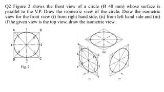
Q2 Figure 2shows the front view of a circle (Ø 40 mm) whose surface is
parallel to the V.P. Draw the isometric view of the circle. Draw the isometric
view for the front view (i) from right hand side, (ii) from left hand side and (iii)
if the given view is the top view, draw the isometric view.
10.
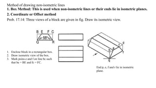
Method of drawingnon-isometric lines
1. Box Method: This is used when non-isometric lines or their ends lie in isometric planes.
2. Coordinate or Offset method
Prob. 17.14: Three views of a block are given in fig. Draw its isometric view.
End p, e, f and r lie in isometric
plane.
1. Enclose block in a rectangular box.
2. Draw isometric view of the box.
3. Mark poins e and f on line bc such
that be = BE and fc = FC.
11.
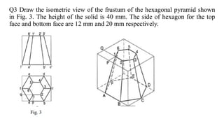
Q3 Draw theisometric view of the frustum of the hexagonal pyramid shown
in Fig. 3. The height of the solid is 40 mm. The side of hexagon for the top
face and bottom face are 12 mm and 20 mm respectively.
12.
Method of drawingnon-isometric lines
2. Coordinate or Offset method: This is used for objects in which neither non-
isometric lines nor their ends lie in isometric planes.
13.
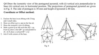
Q4 Draw theisometric view of the pentagonal pyramid, with (i) vertical axis perpendicular to
base (ii) vertical axis in horizontal position. The projections of pentagonal pyramid are given
in Fig. 4. The side of pentagon is 30 mm and height of pyramid is 40 mm.
Coordinate or Offset method:
1. Enclose the base in an oblong with 2 long
and 2 small sides.
2. Draw an offset oq (i.e. pq) on the line ab.
3. Draw the isometric view of oblong.
4. Mark a point Q on AB such that AQ = aq.
From Q, draw a line QP= qo and parallel to
2C. At P, draw a vertical OP = o’p’.
5. Join O with corners of the base.
14.
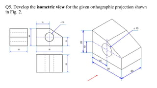
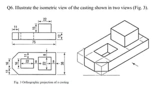
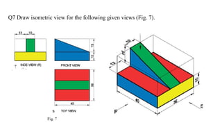
Q5. Develop theisometric view for the given orthographic projection shown
in Fig. 2.
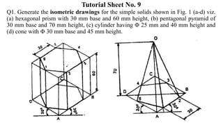
Tutorial Sheet No.9
Q1. Generate the isometric drawings for the simple solids shown in Fig. 1 (a-d) viz.
(a) hexagonal prism with 30 mm base and 60 mm height, (b) pentagonal pyramid of
30 mm base and 70 mm height, (c) cylinder having Φ 25 mm and 40 mm height and
(d) cone with Φ 30 mm base and 45 mm height.
22.
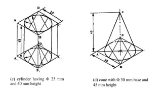
(c) cylinder havingΦ 25 mm
and 40 mm height
(d) cone with Φ 30 mm base and
45 mm height
23.
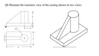
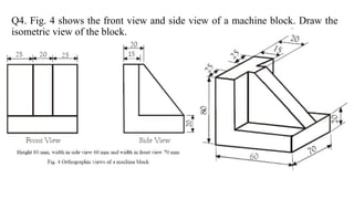
Q4. Fig. 4shows the front view and side view of a machine block. Draw the
isometric view of the block.