The document discusses enhanced equipment quality assurance (EEQA) and equipment health monitoring (EHM) methods to ensure reliable semiconductor manufacturing equipment. It provides:
1) An overview of the EEQA and EHM projects, including goals to reduce equipment variability and efficiently track performance.
2) Details on EEQA approaches like collecting equipment data to validate functional capabilities and monitor variations.
3) The 2011 EHM project timeline and objectives to demonstrate fingerprinting effectiveness using an equipment data model.
4) An equipment fingerprinting pilot to refine use cases and demonstrate the fingerprinting process using real manufacturing data.

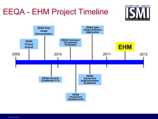


![2011 Equipment Health Monitoring
(EHM)Project Objectives class DataSourceTypes
«XSDcomplexT ype»
DataSourceModel
Demonstrate effectiveness of data
+SourceId
1..1 1..1
+RootLocation
«XSDcomplexType»
«XSDcomplexT ype» DataSourceId
DataSourceLocation
«XSDattribute»
+ChildLocation 0..*
+ Name: Path
model usage for fingerprint scenarios
«XSDattribute»
+ Name: Path + Type: DataSourceT ype
+Dictionary
1..1
«XSDcomplexT ype»
DataSourceDictionary
Create industry guidance showing the «XSDcomplexType»
«XSDattribute»
Descriptor
application and usage of the proposed
- Description: Description [0..1]
- Key: KeyType
- Name: Name
data model for fingerprinting
+Event
0..* +Parameter 0..*
«XSDcomplexT ype» «XSDcomplexT ype»
ParameterDescriptor Ev entDescriptor
string
«XSDattribute» «XSDattribute»
+ DataT ype: ParameterDataT ype «XSDsimpleType» + Category: EventCategoryType [0..1]
+ ScalingFactor: float [0..1] ParameterValueType + SubCategory: EventCategoryType [0..1]
+ Units: ParameterUnits [0..1]
Create guidance for practical creation «XSDextension»
+ParameterRef
«XSDcomplexT ype»
0..*
and use of equipment health
ParameterRefType
«XSDattribute»
+ Key: KeyT ype
monitoring and fingerprinting of
components using the data model
Demonstrate standardized methods,
data requirements and management of
equipment health monitoring and
fingerprinting specifications
April 19, 2012](https://image.slidesharecdn.com/eeqaehmhistoryshort-13348353062109-phpapp01-120419063828-phpapp01/85/EEQA-and-EHM-Background-10-320.jpg)


![class DataSourceTypes
«XSDcomplexType»
DataSource
+Child 0..*
«XSDattribute»
+ Path: PathType
+ Type: string
«XSDtopLevelElement»
RootDataSource
1..1
+Dictionary
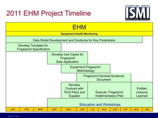
Equipment
«XSDcomplexType»
DataSourceDictionary Data Model
«XSDcomplexType»
Transformation
Descriptor
«XSDattribute»
+ Description: string [0..1]
+ Key: KeyType
+ Name: NameType Equipment data
+Parameter +Event
model defines
0..*
«XSDcomplexType»
0..*
«XSDcomplexType»
and correlates
ParameterDescriptor Ev entDescriptor
event and data
«XSDattribute»
+ DataType: ParameterDataType
+ ScalingFactor: float [0..1]
«XSDattribute»
+ Category: string [0..1]
+ SubCategory: string [0..1]
available in the
+ Units: UnitSymbol
equipment (raw
data) to monitor
+Trigger 0..*
«XSDcomplexType»
equipment
ParameterValueType
«XSDattribute»
health and track
+ Key: KeyType
+ Value: string
performance
April 19, 2012](https://image.slidesharecdn.com/eeqaehmhistoryshort-13348353062109-phpapp01-120419063828-phpapp01/85/EEQA-and-EHM-Background-16-320.jpg)


