This document provides a summary of key concepts related to the analysis and design of retaining structures:
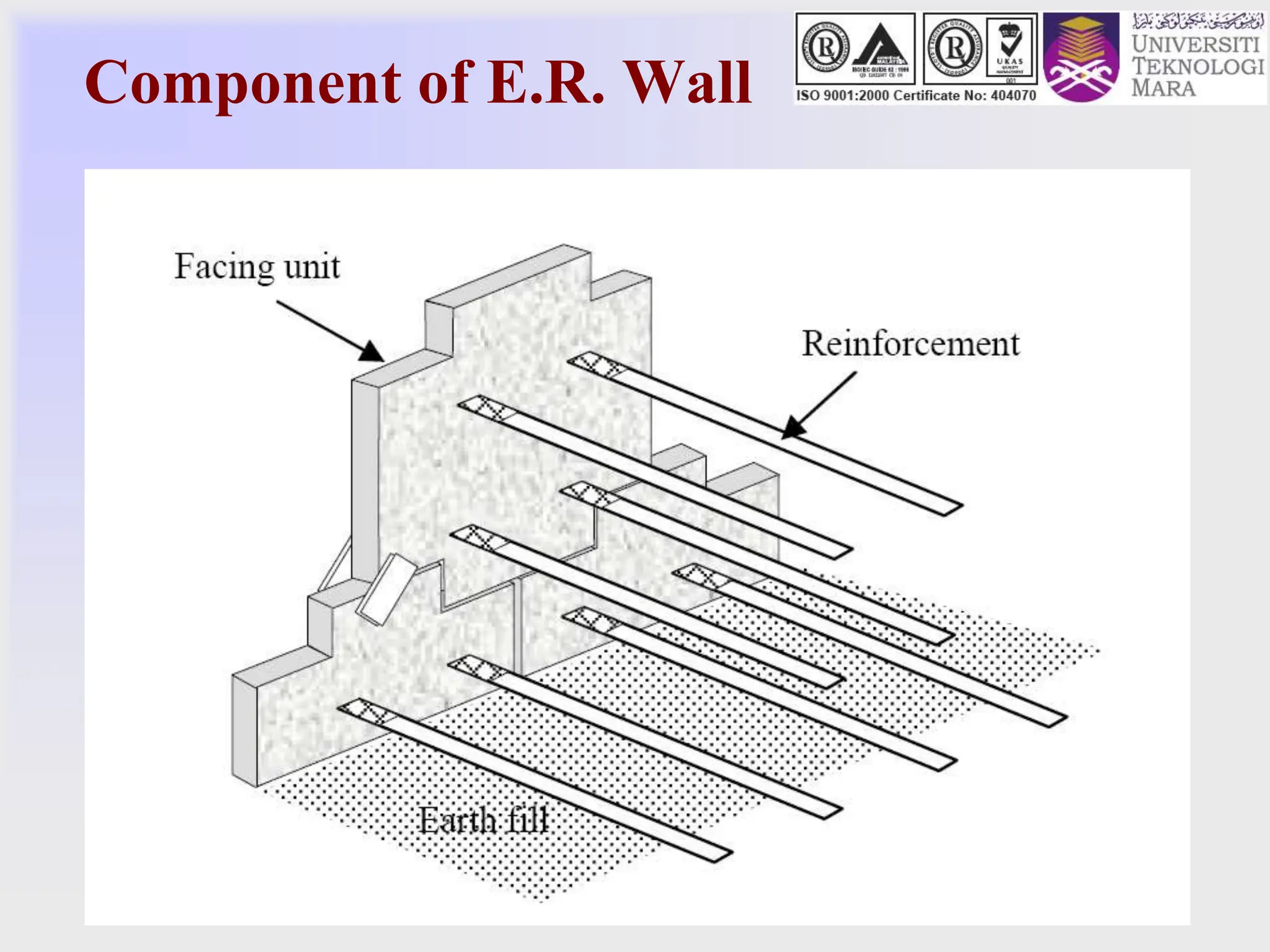
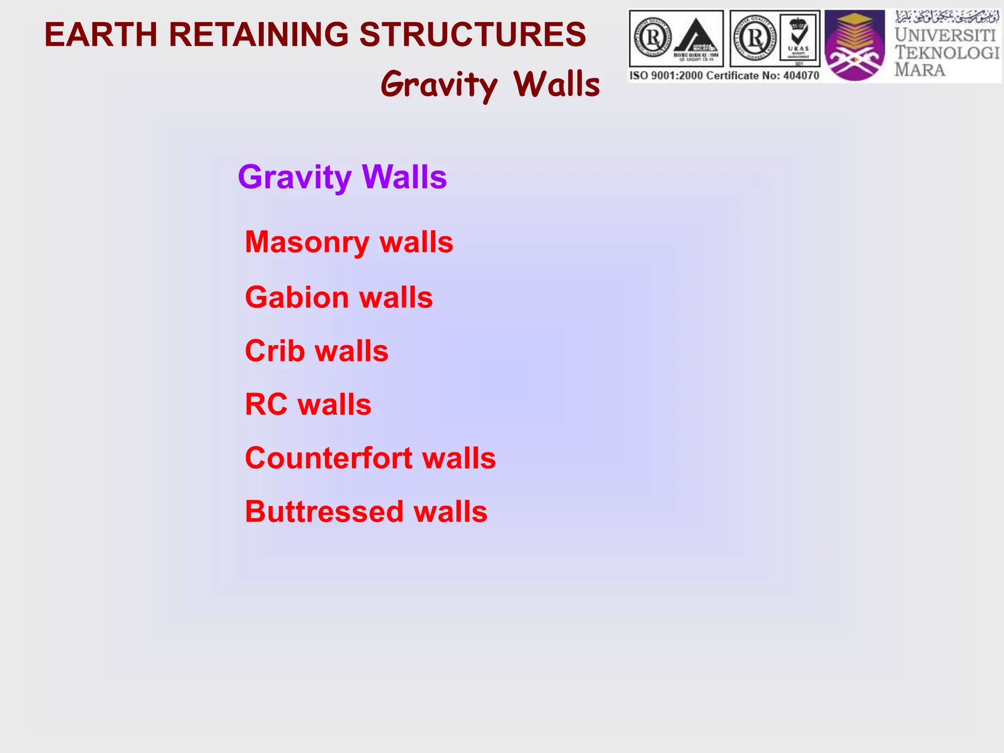
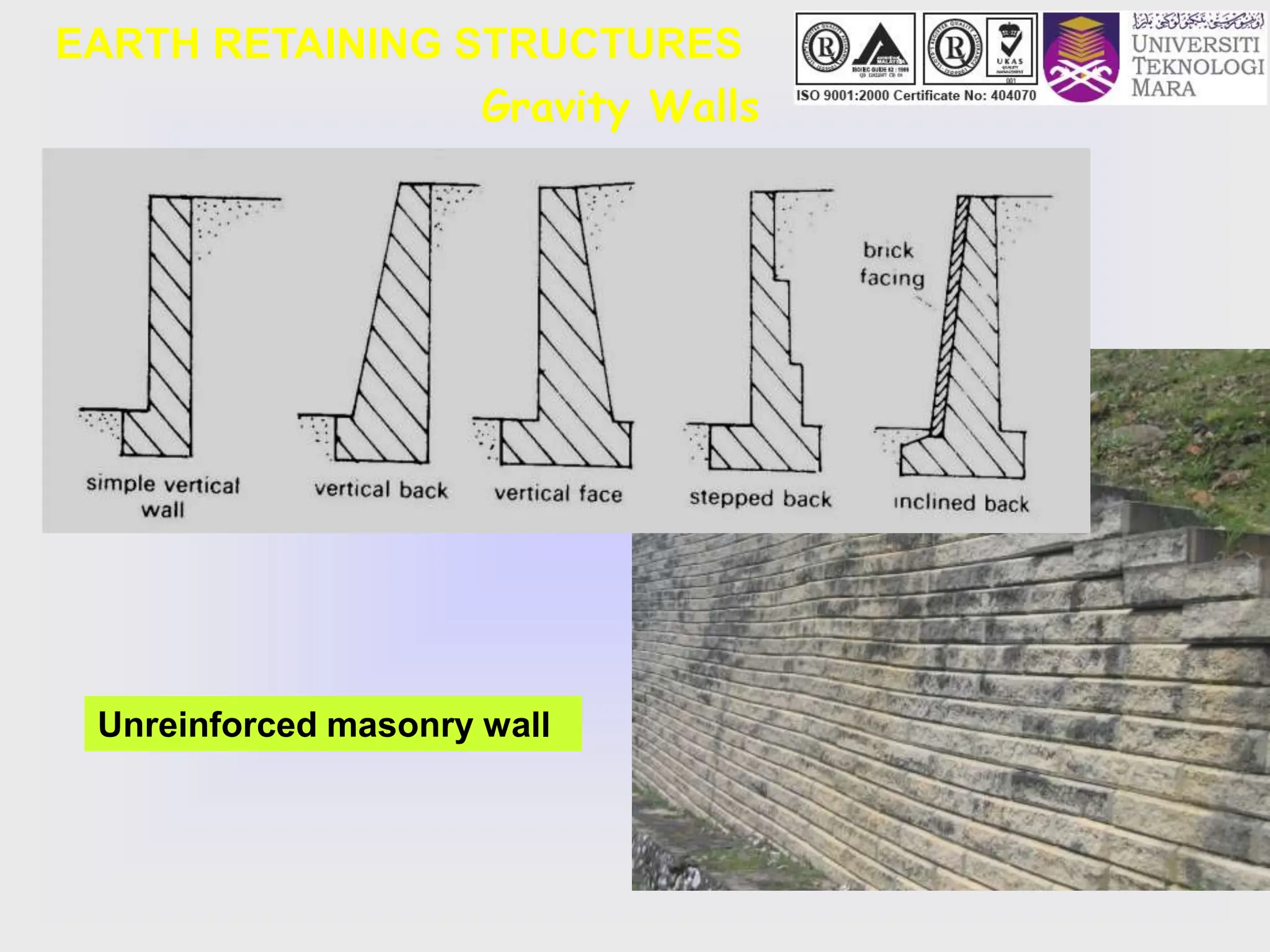
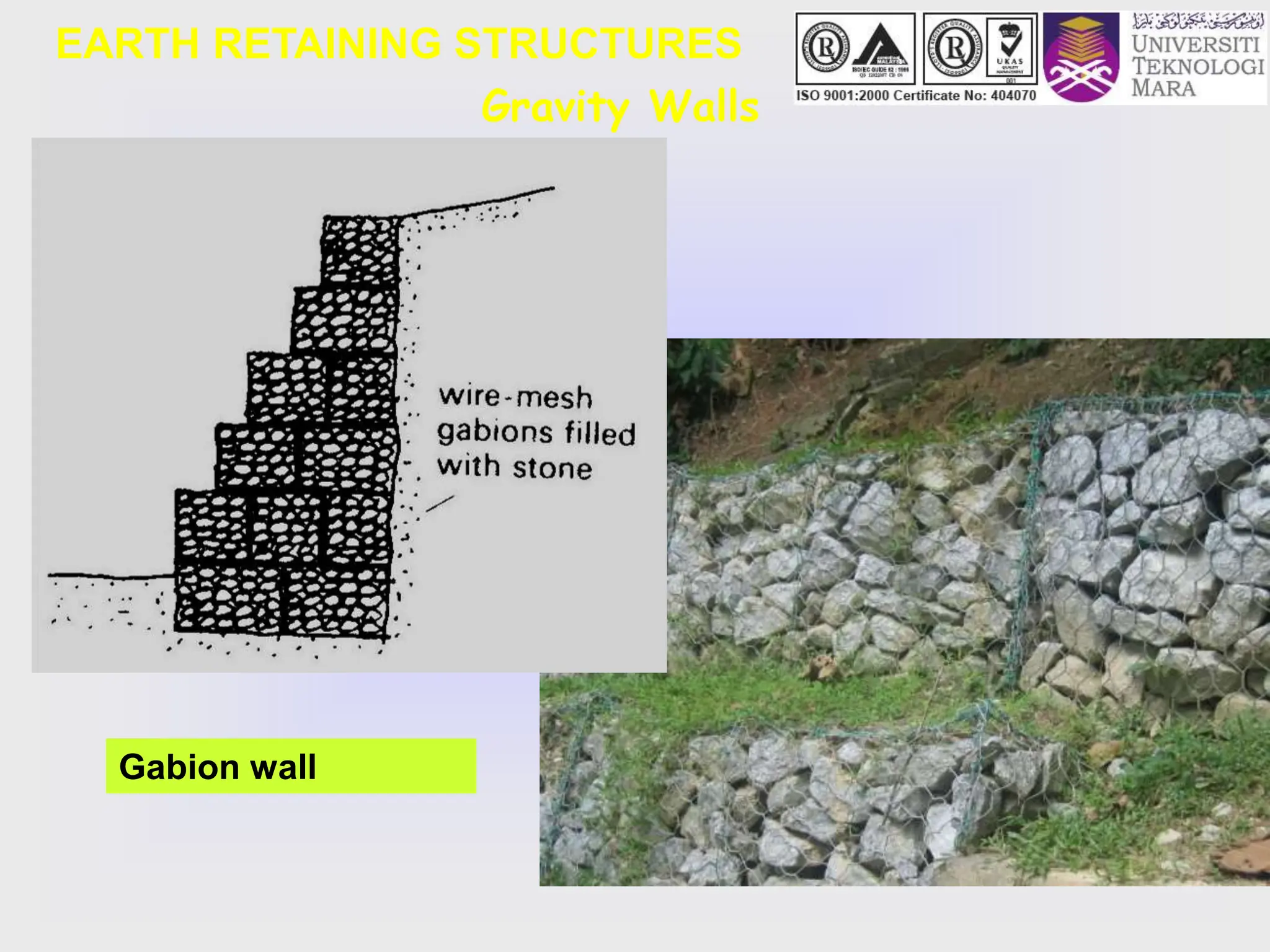
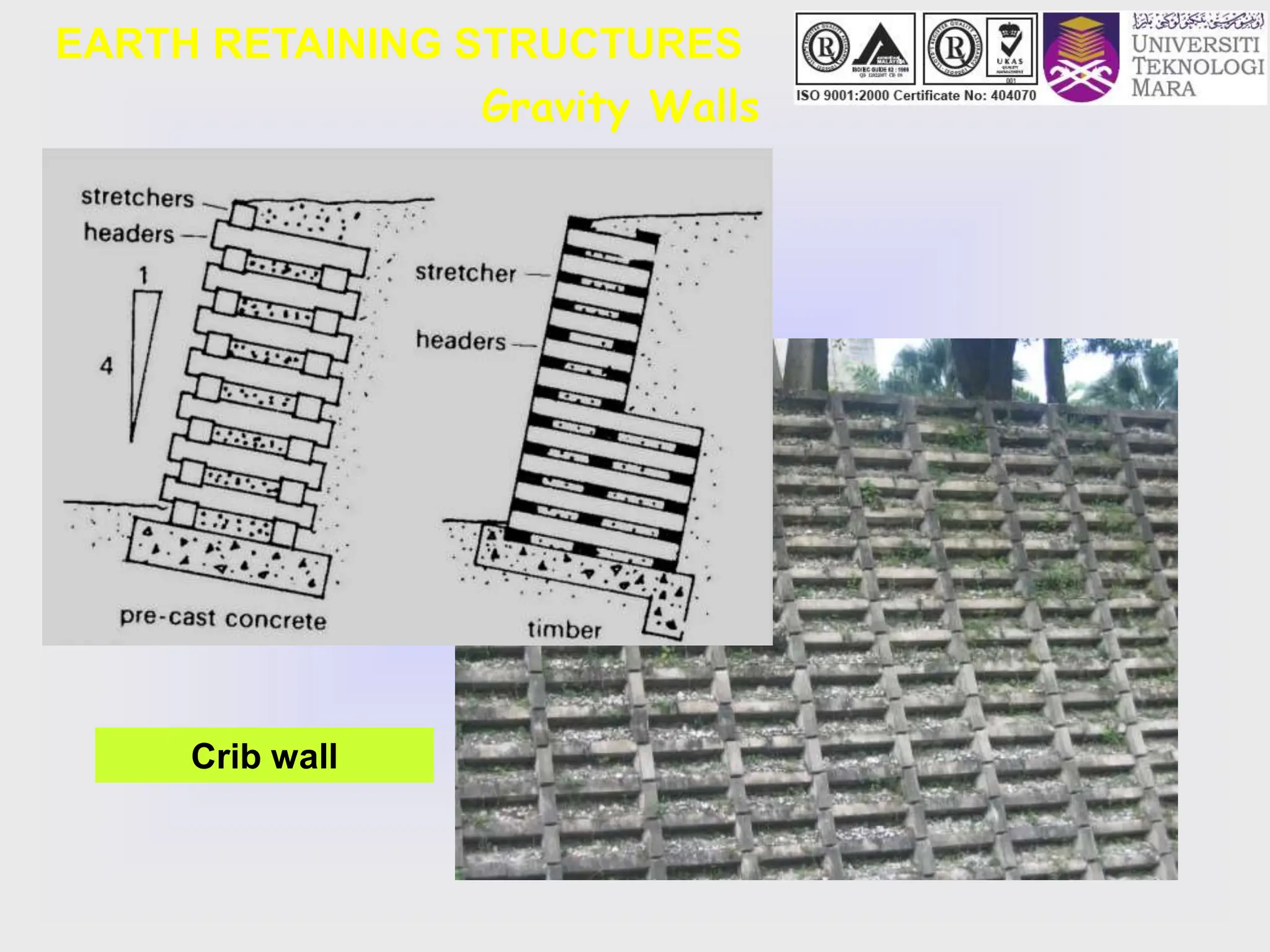
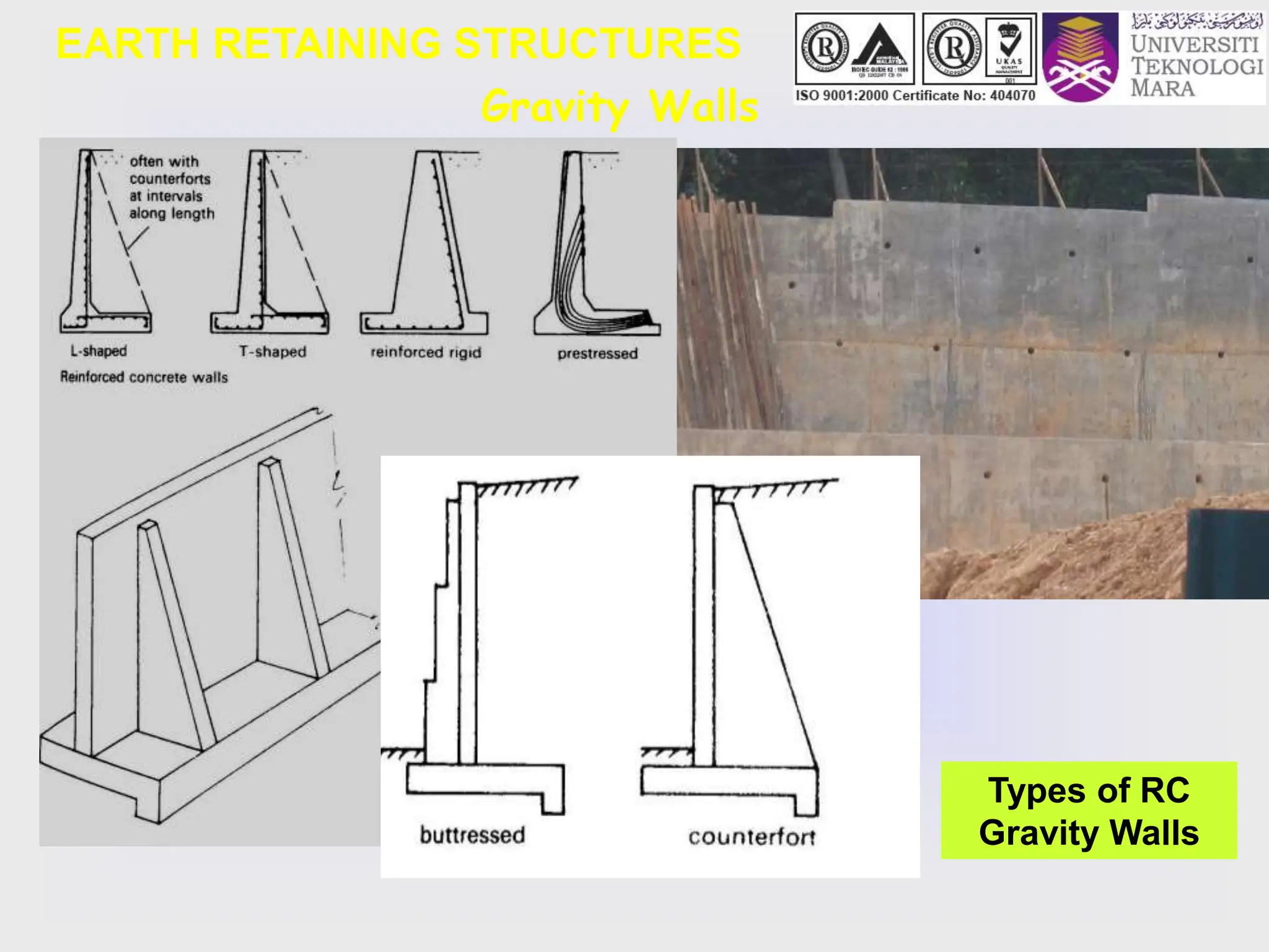
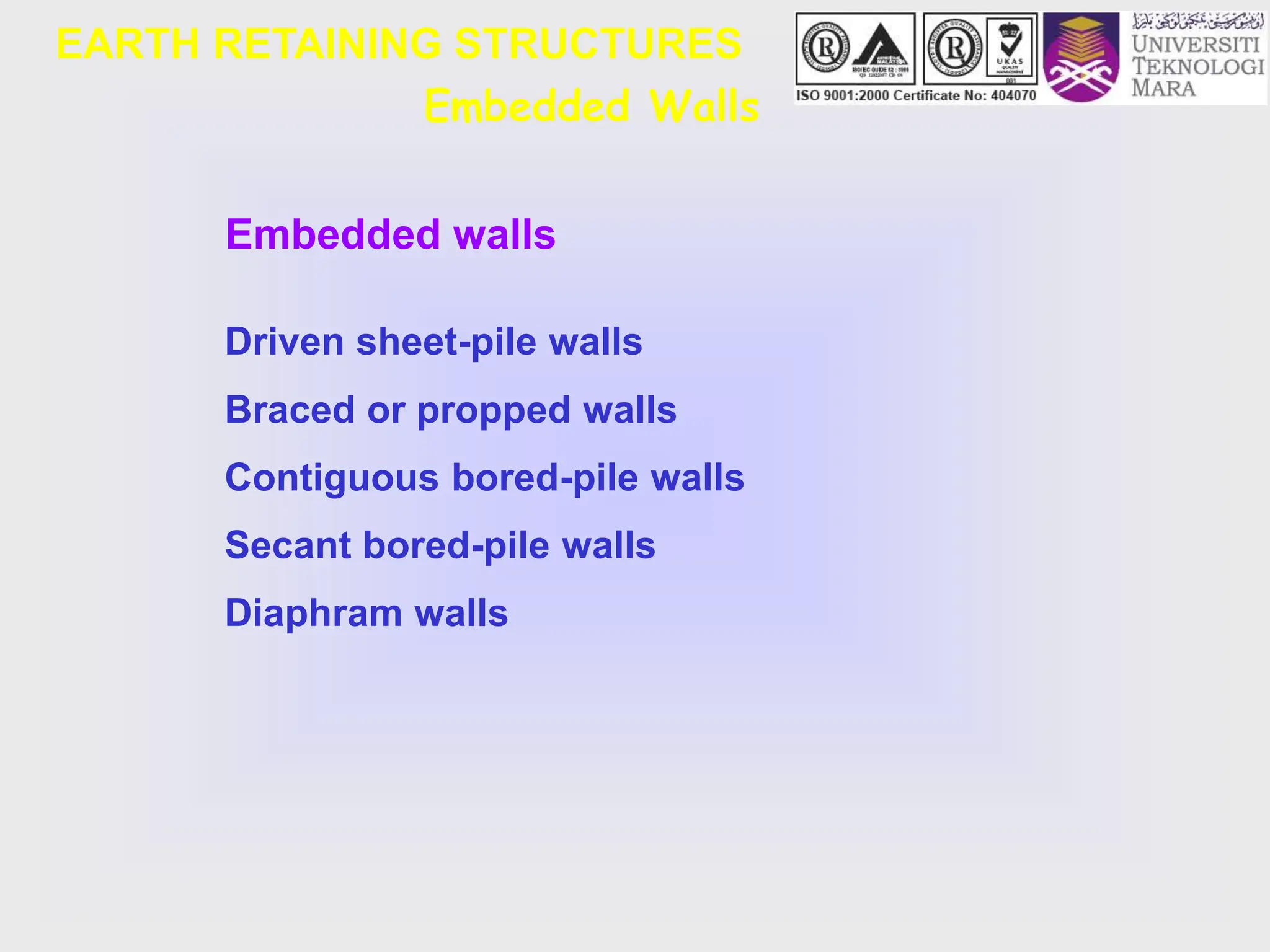
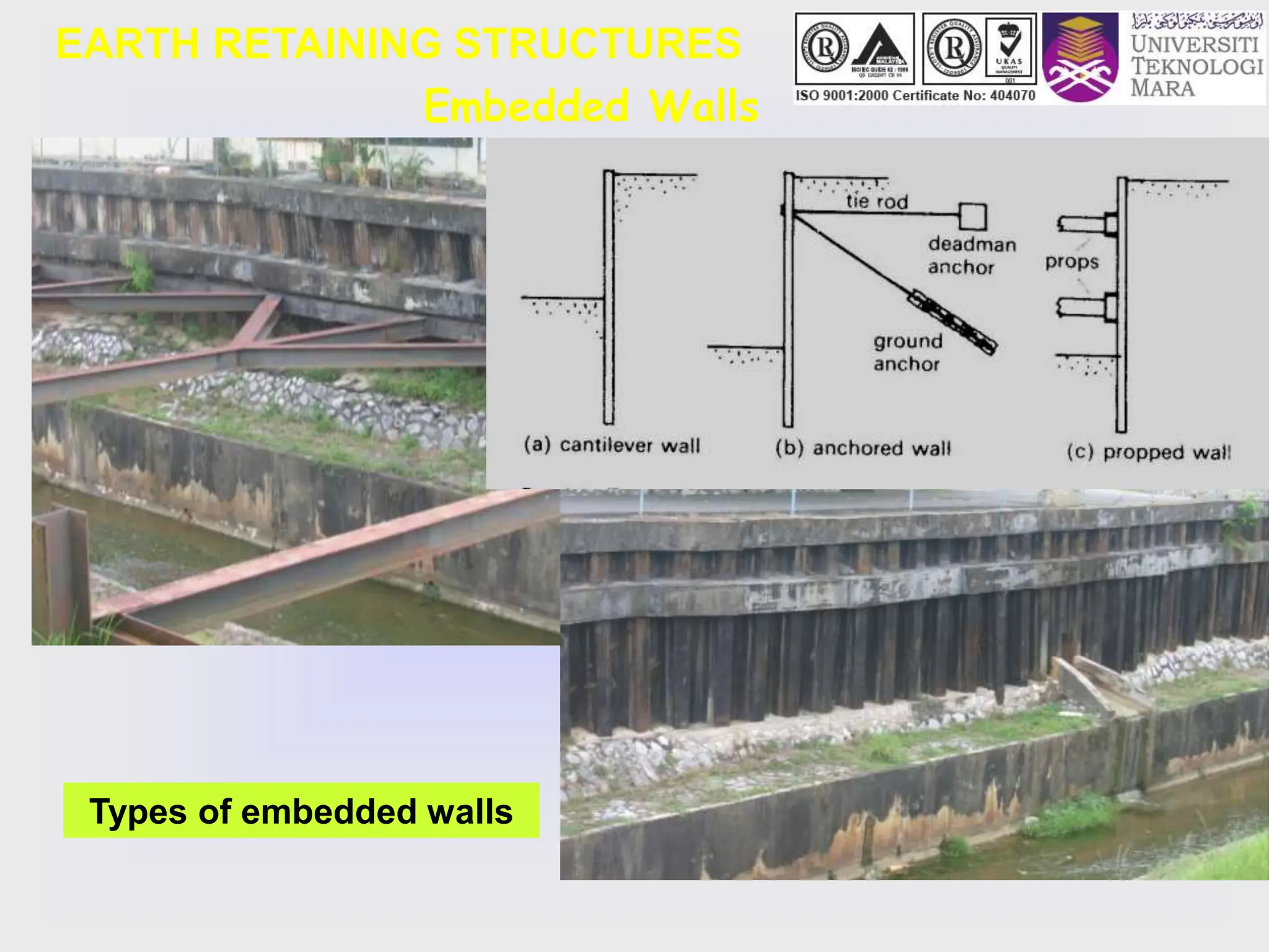
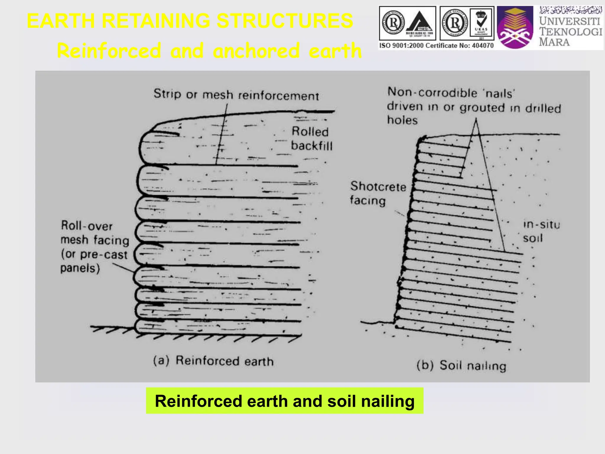
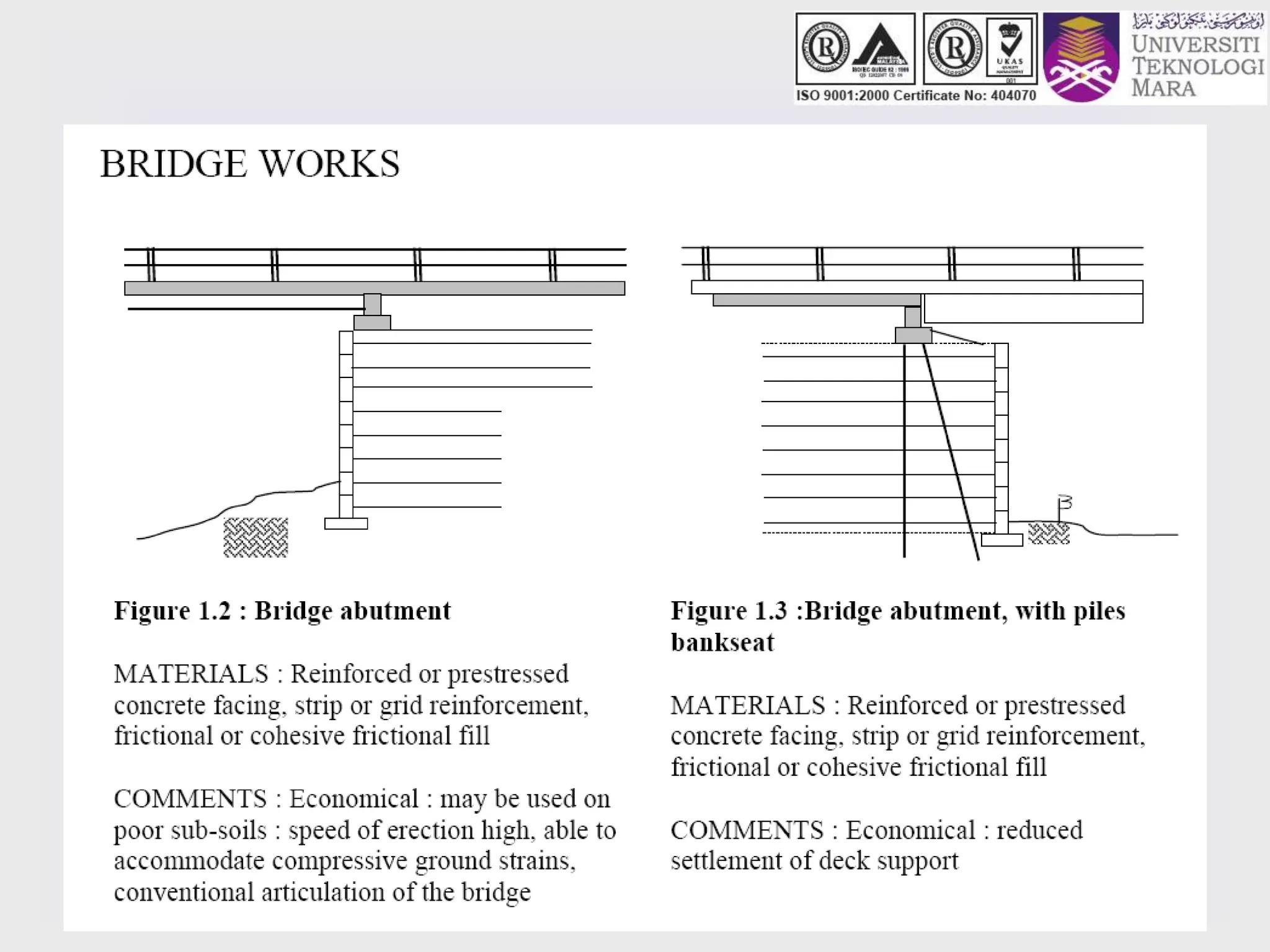
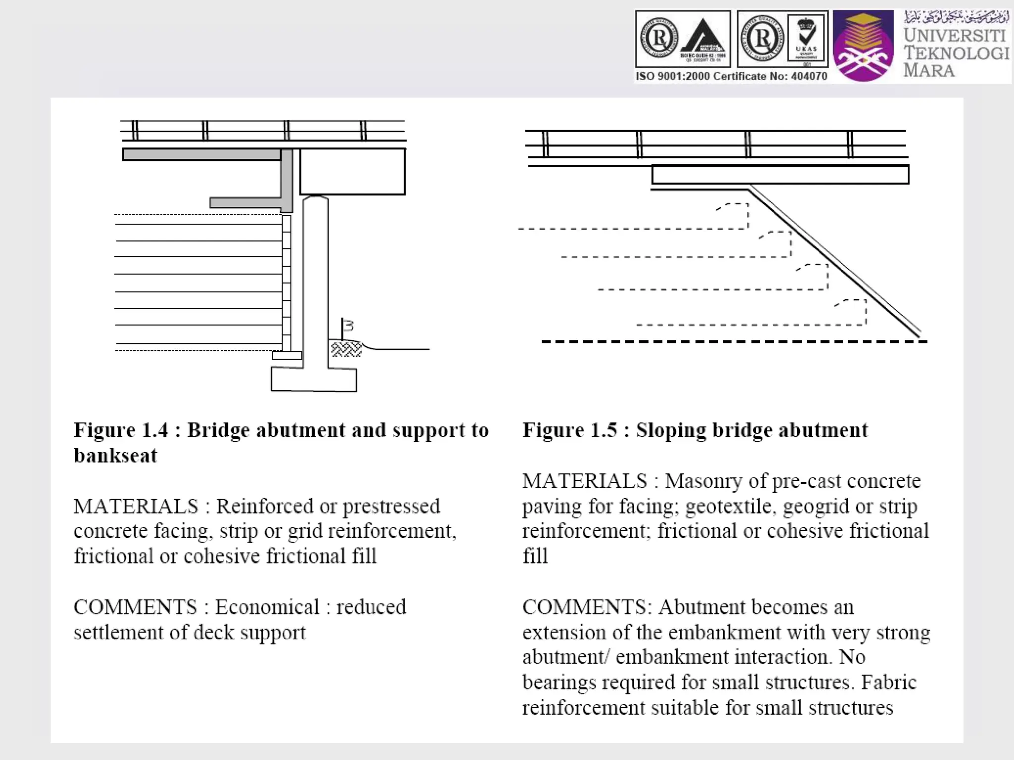
- It discusses different types of retaining structures including gravity walls, embedded walls, and reinforced/anchored earth walls. Common examples like sheet pile walls, cantilever walls, and reinforced earth walls are mentioned.
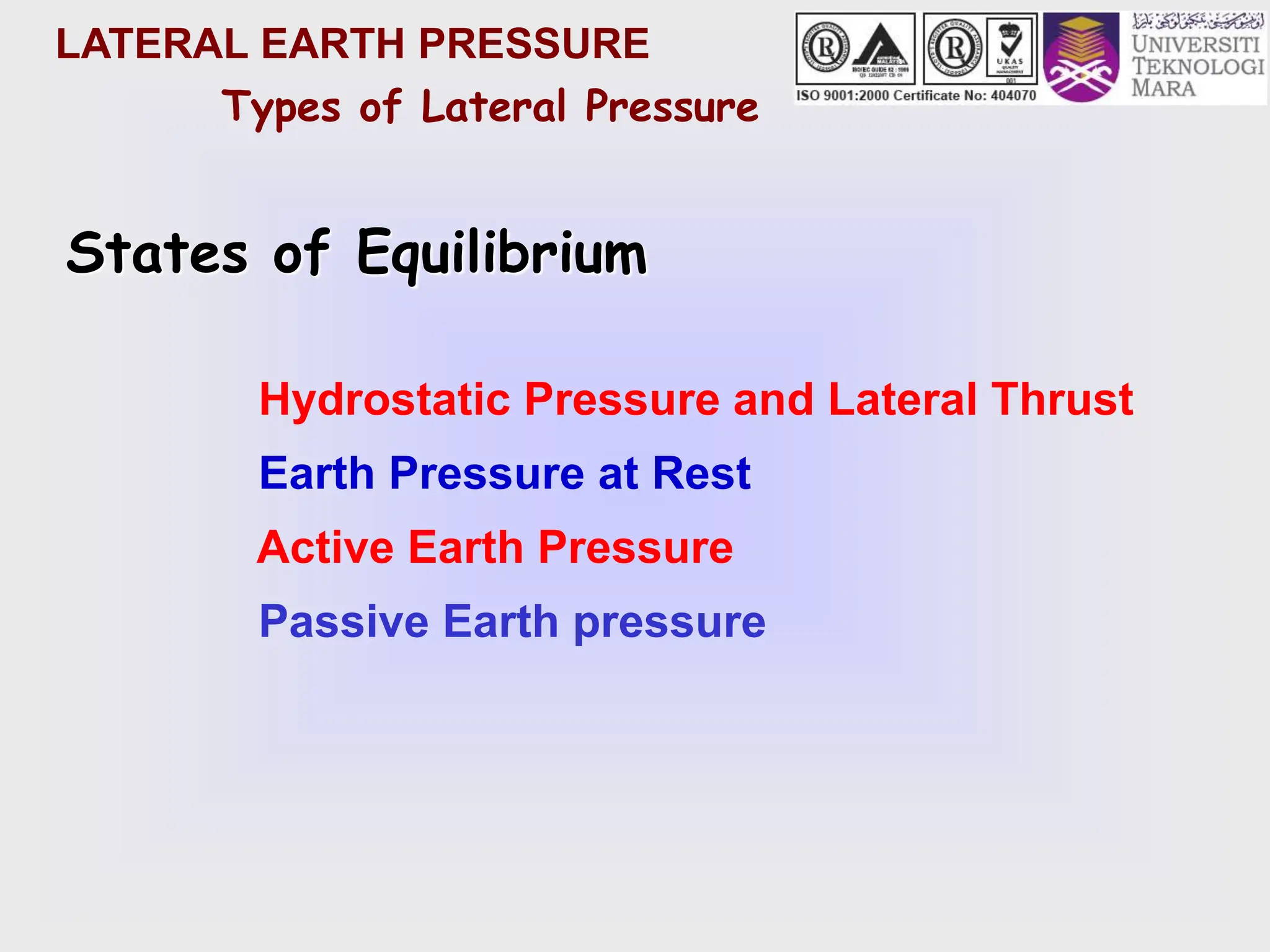
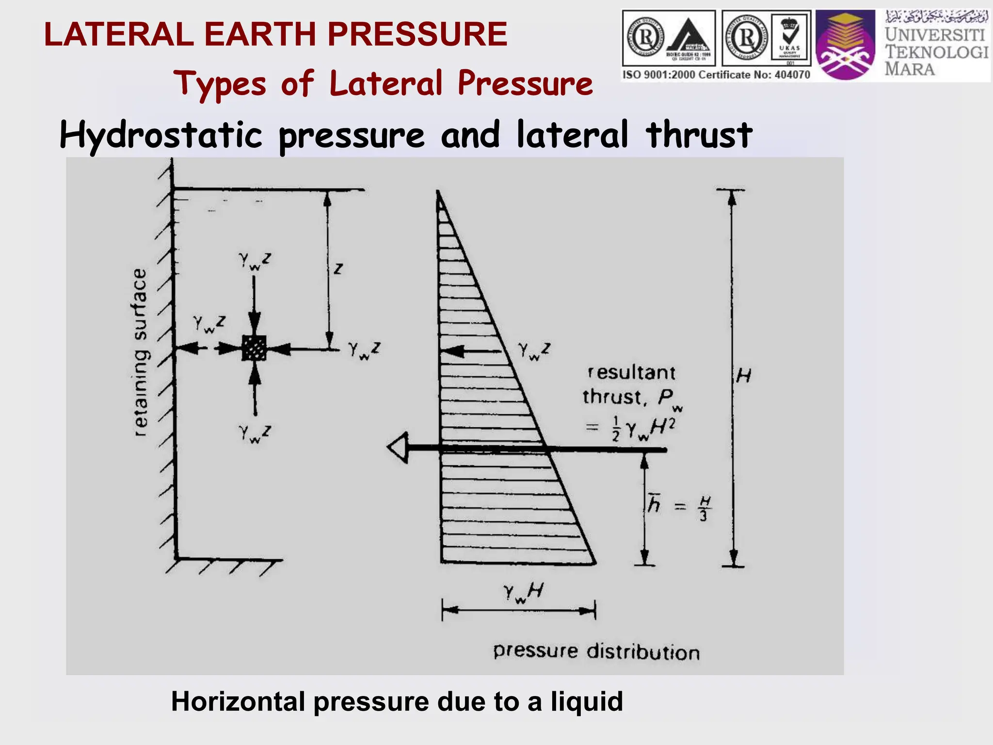
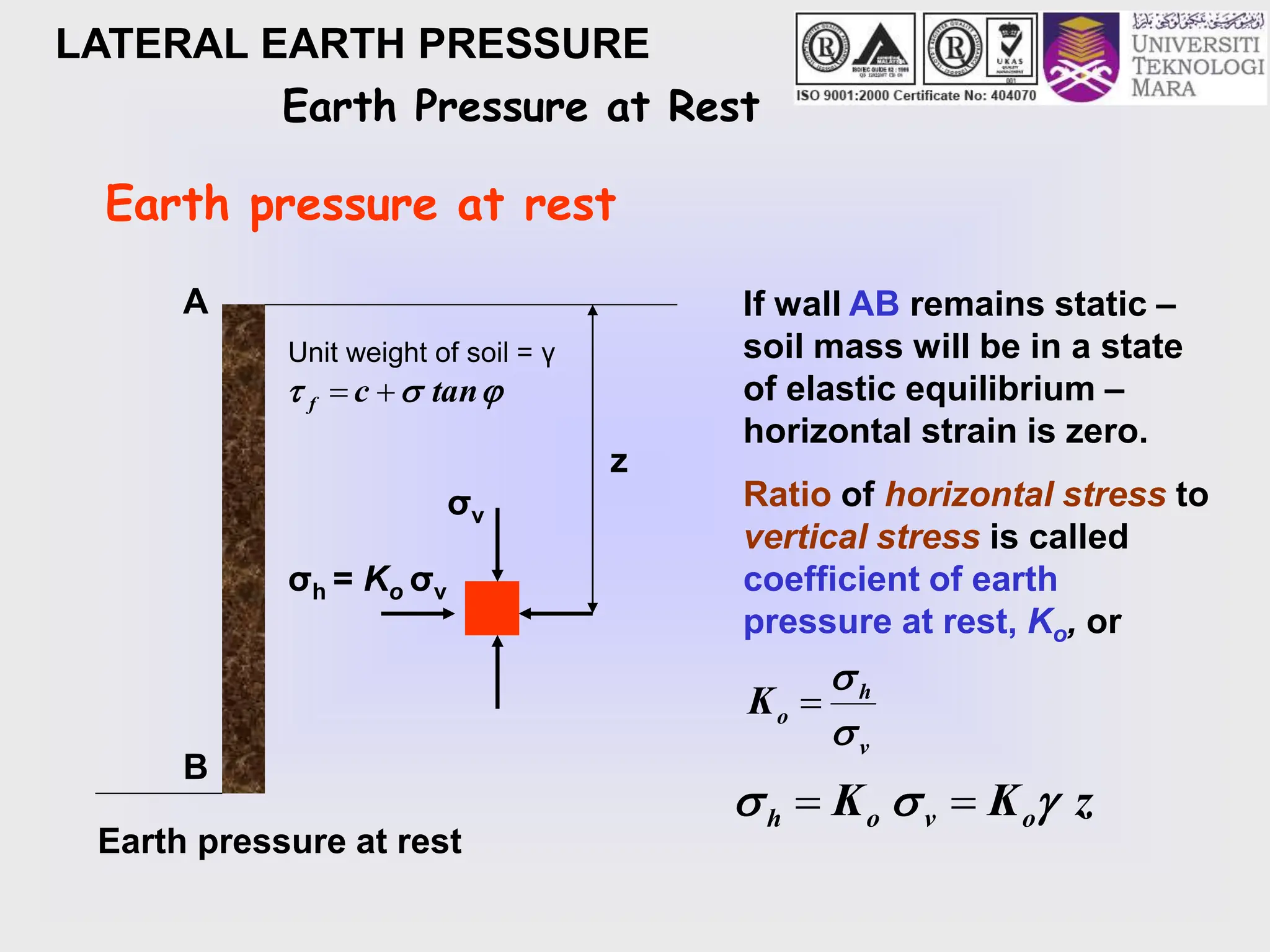
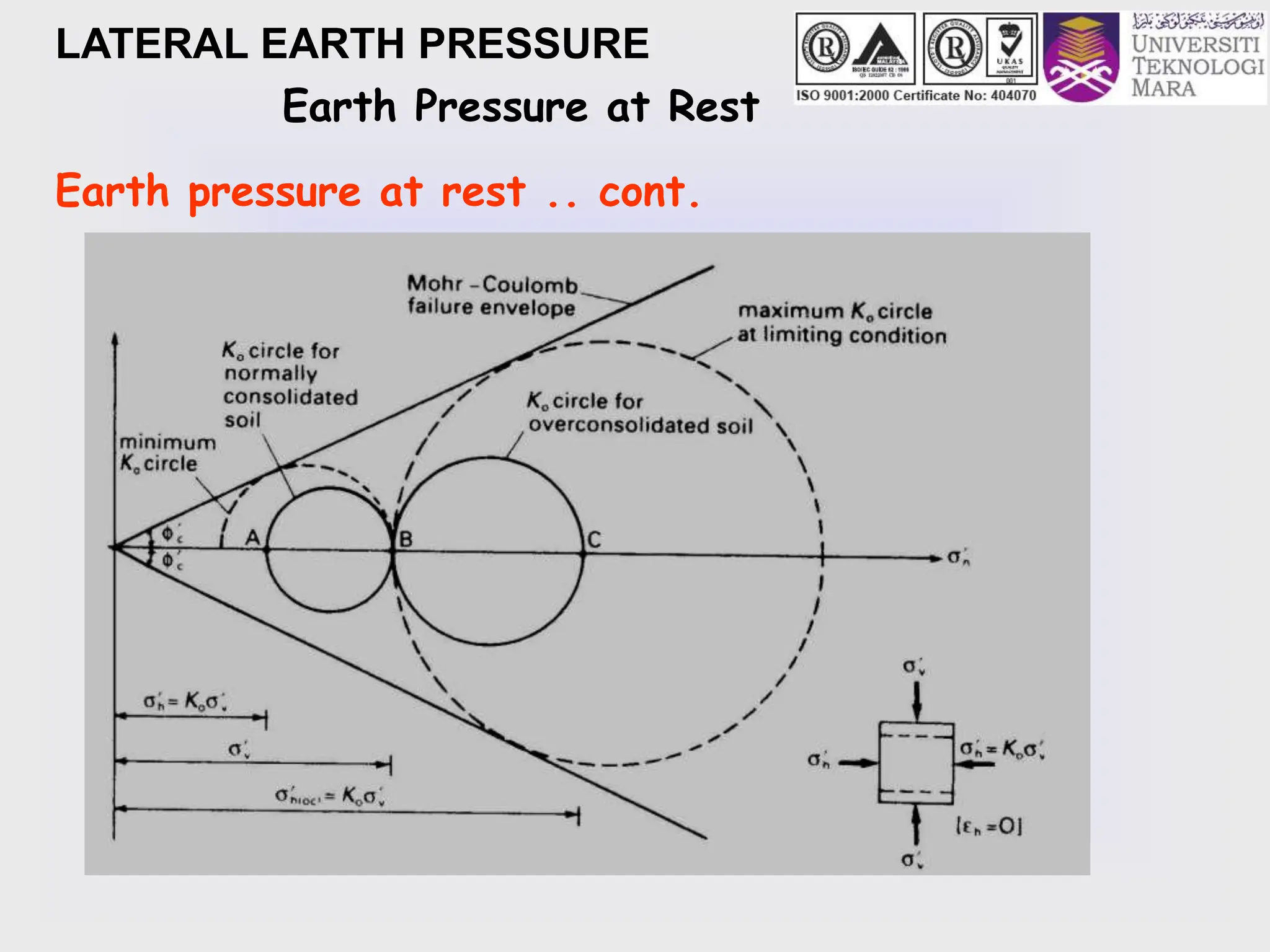
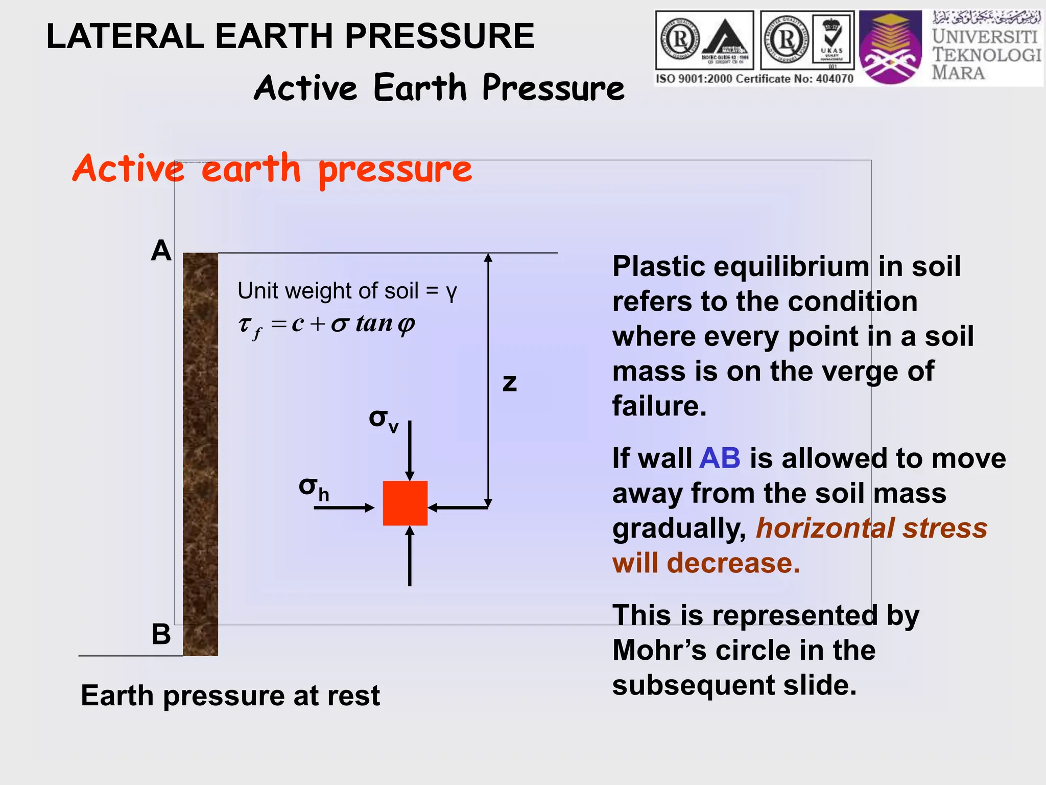
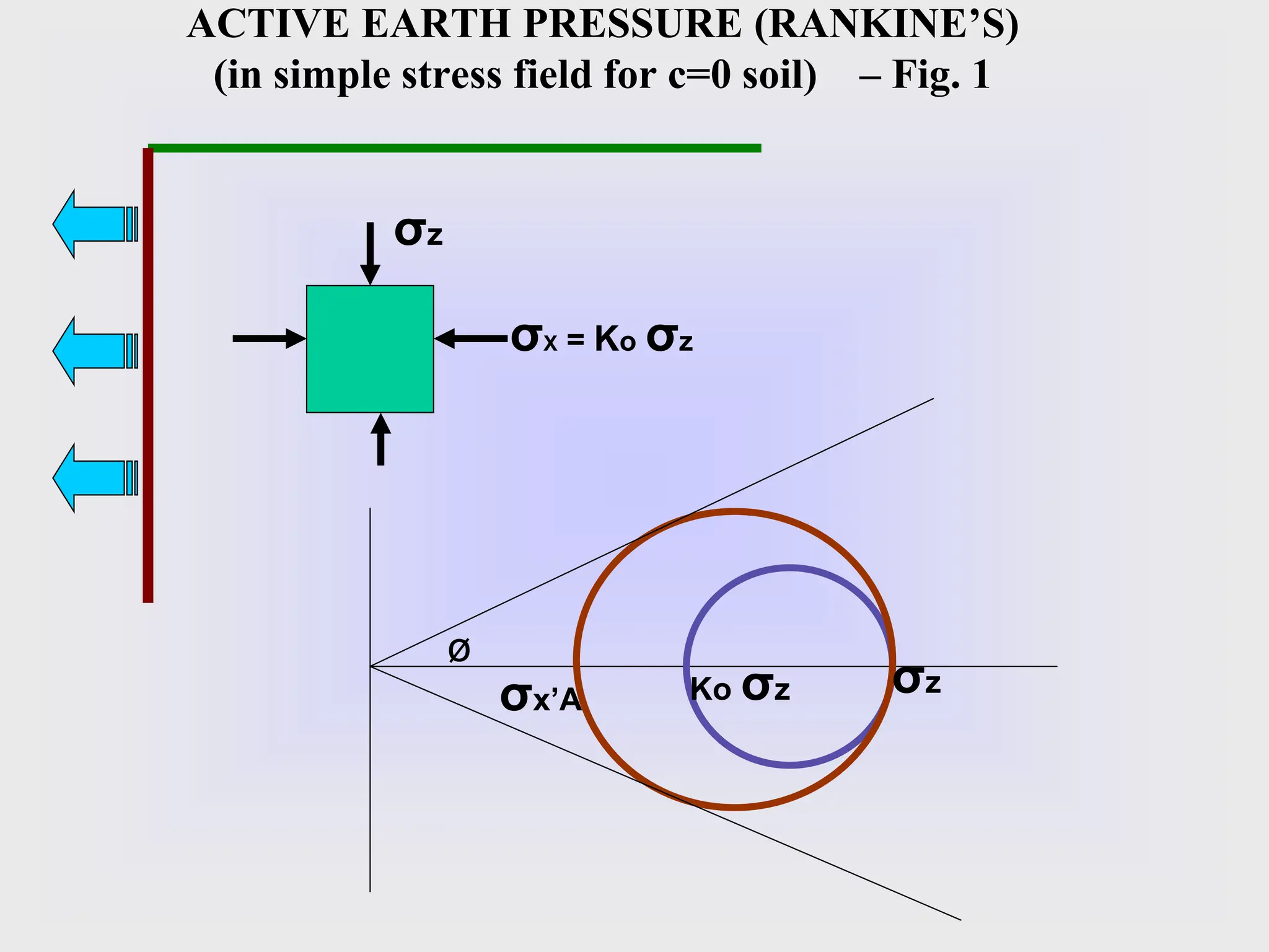
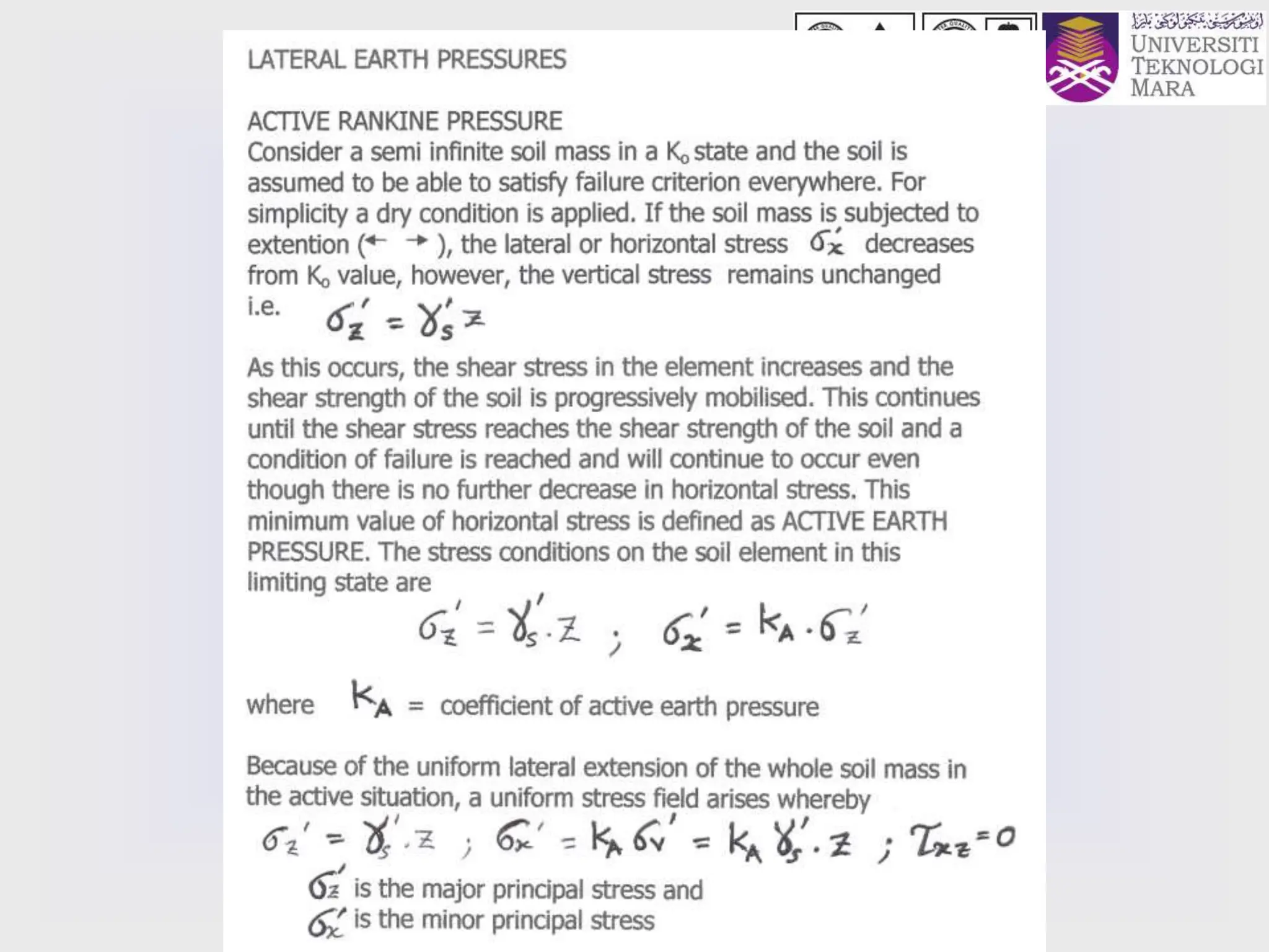
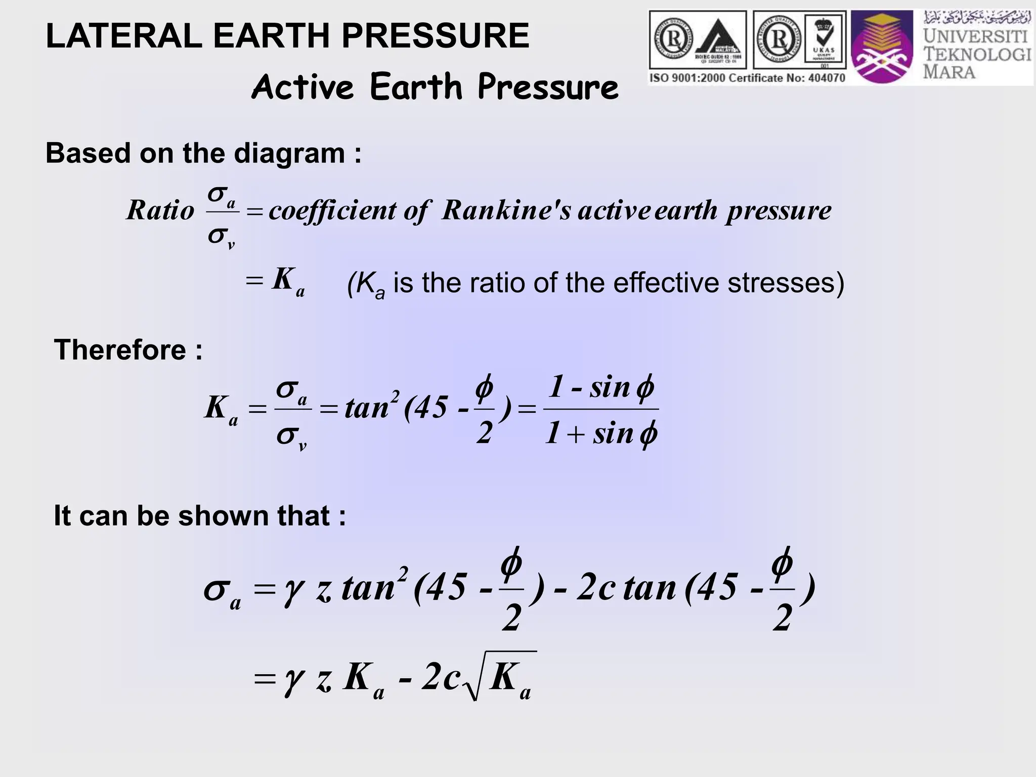
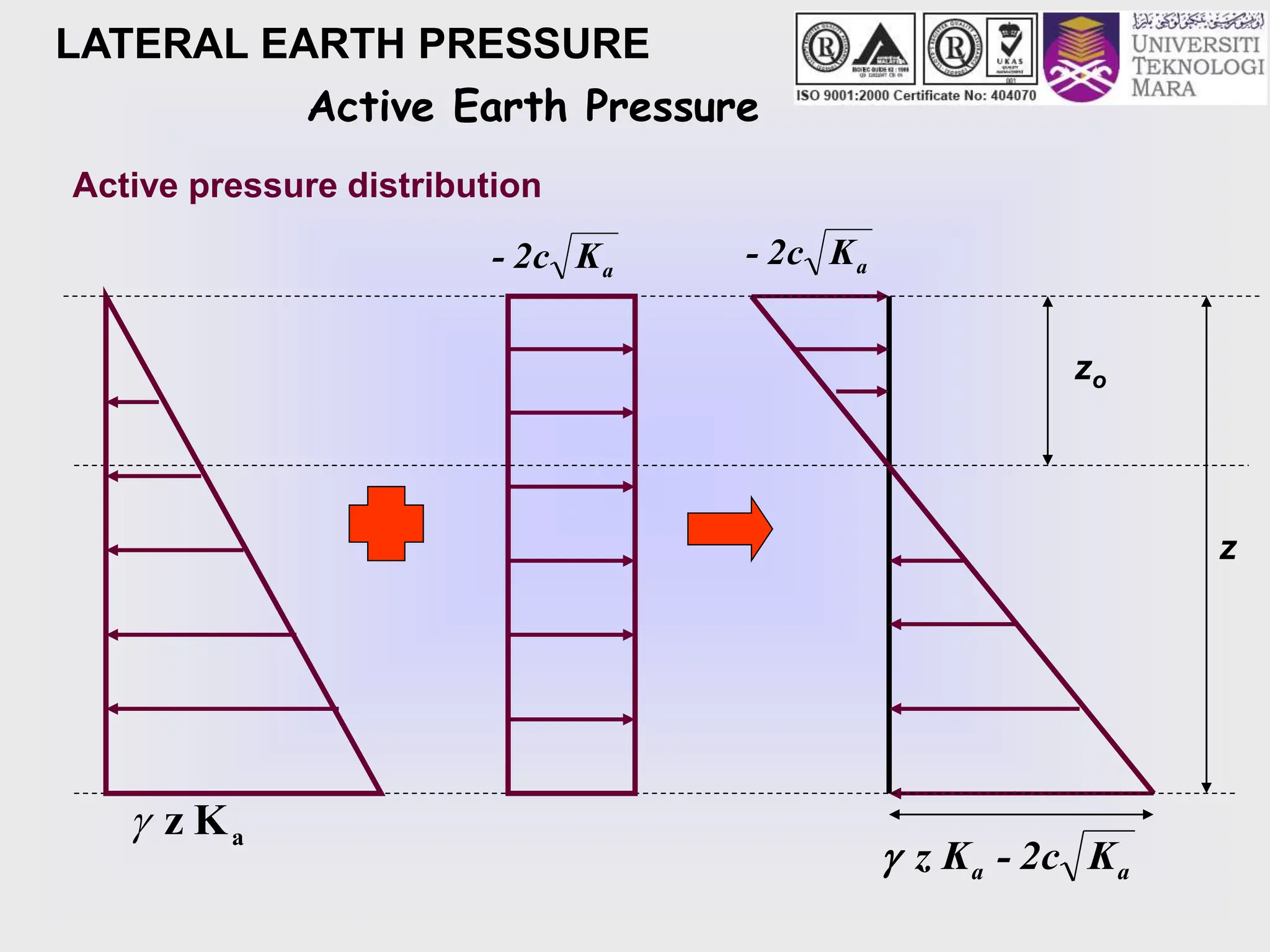
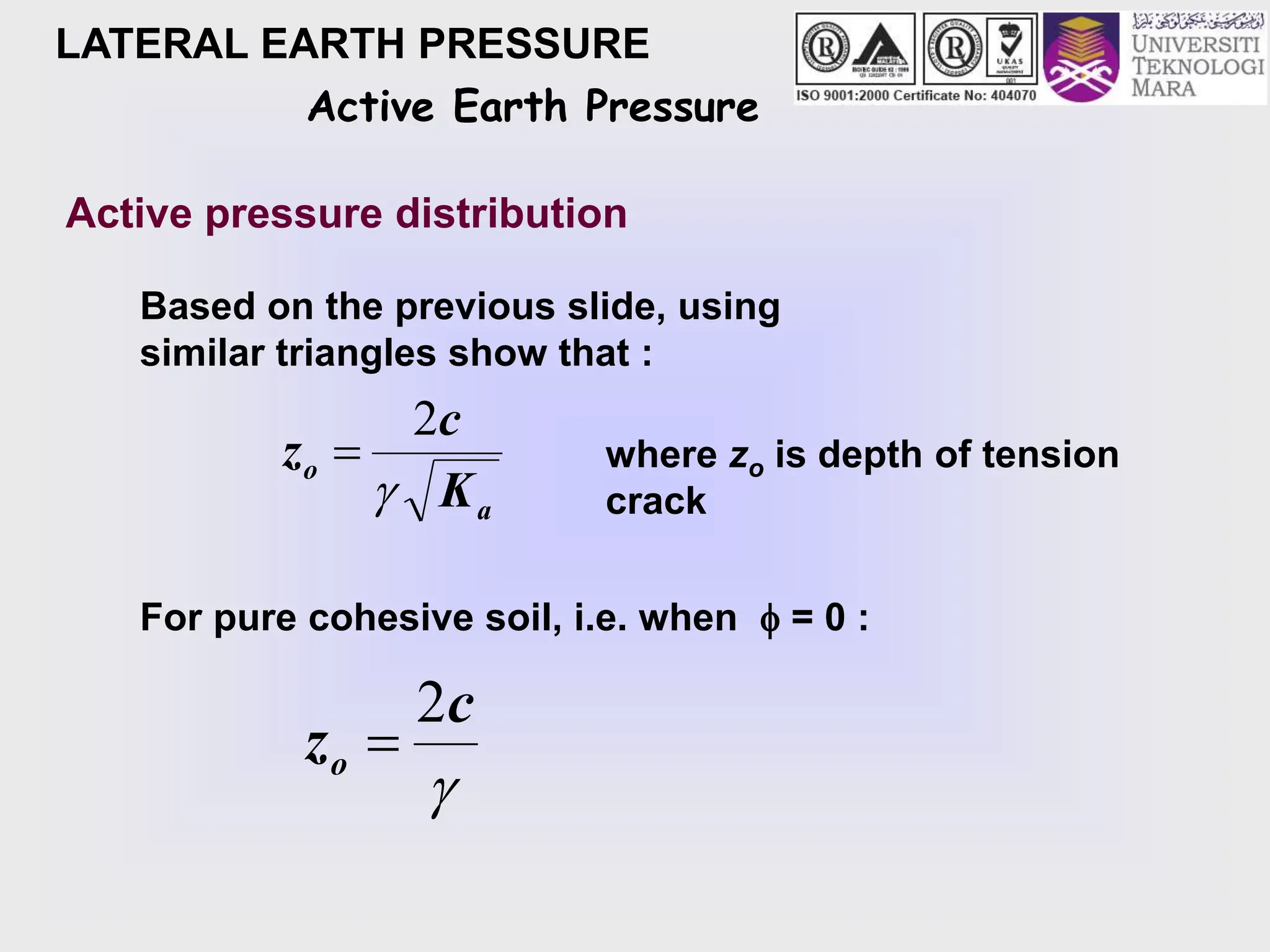
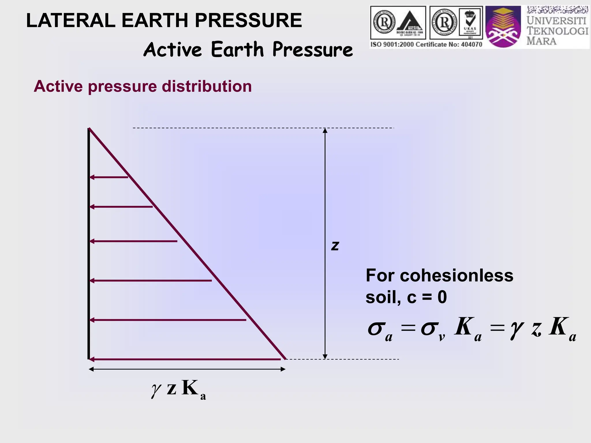
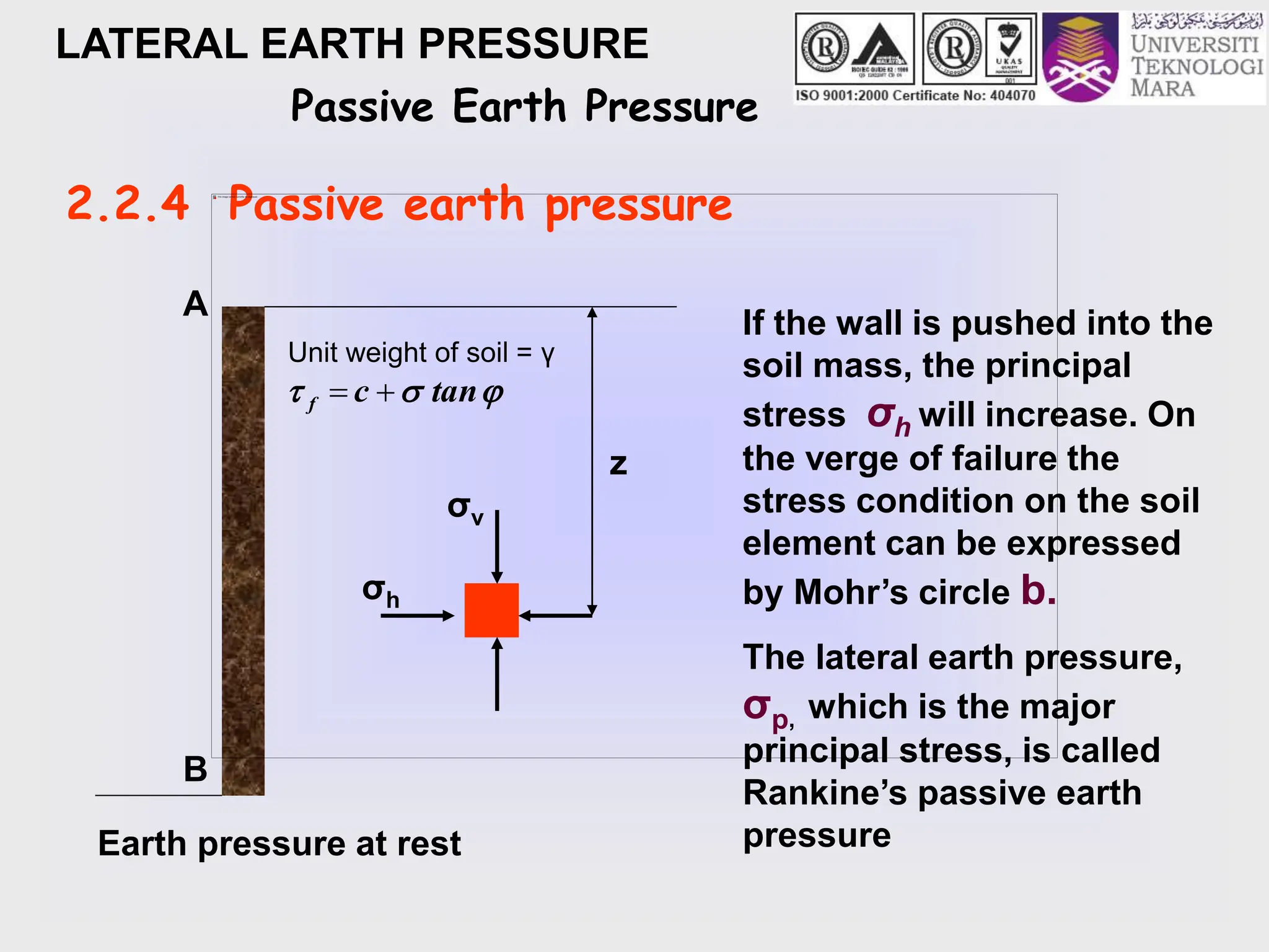
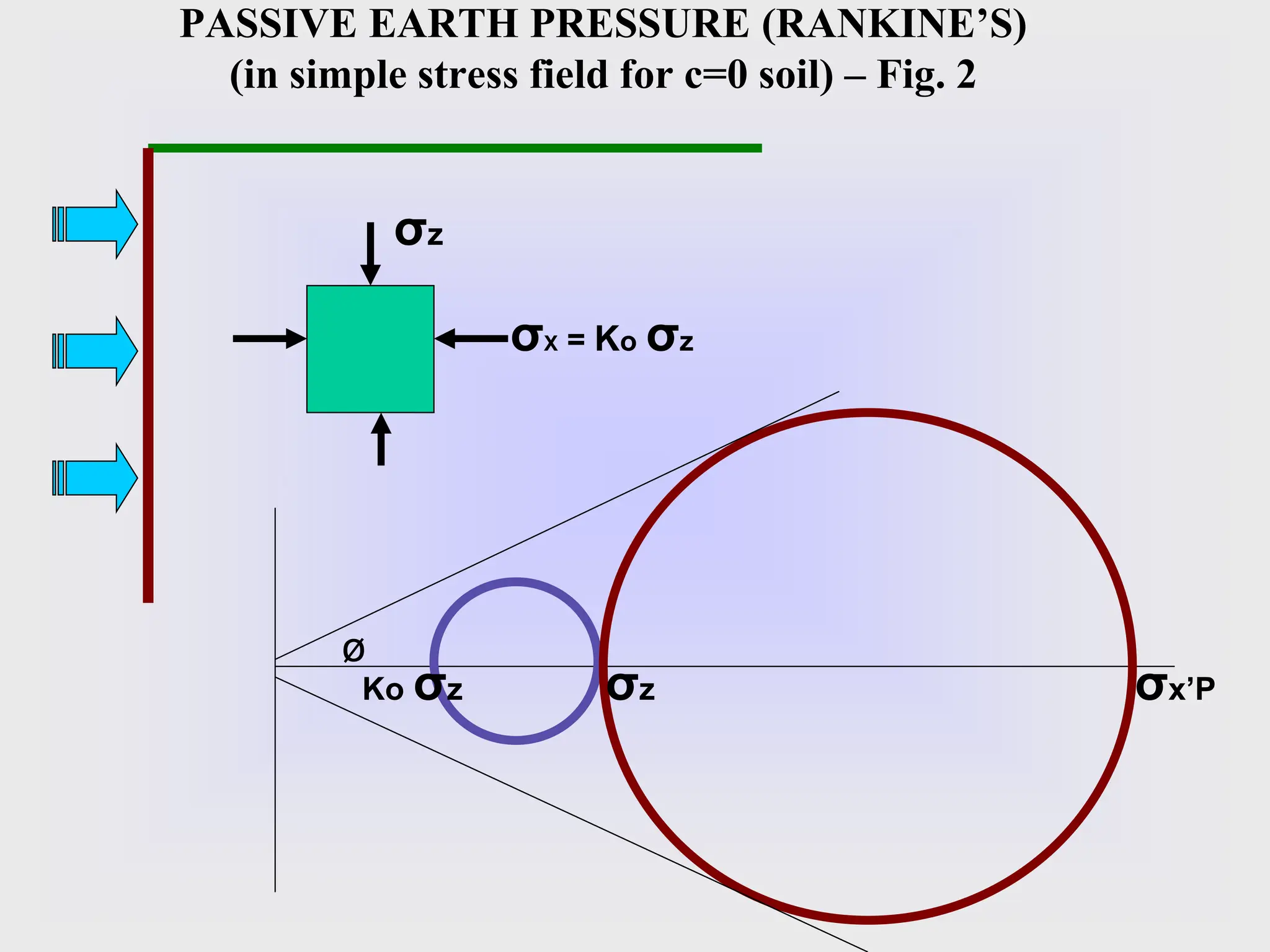
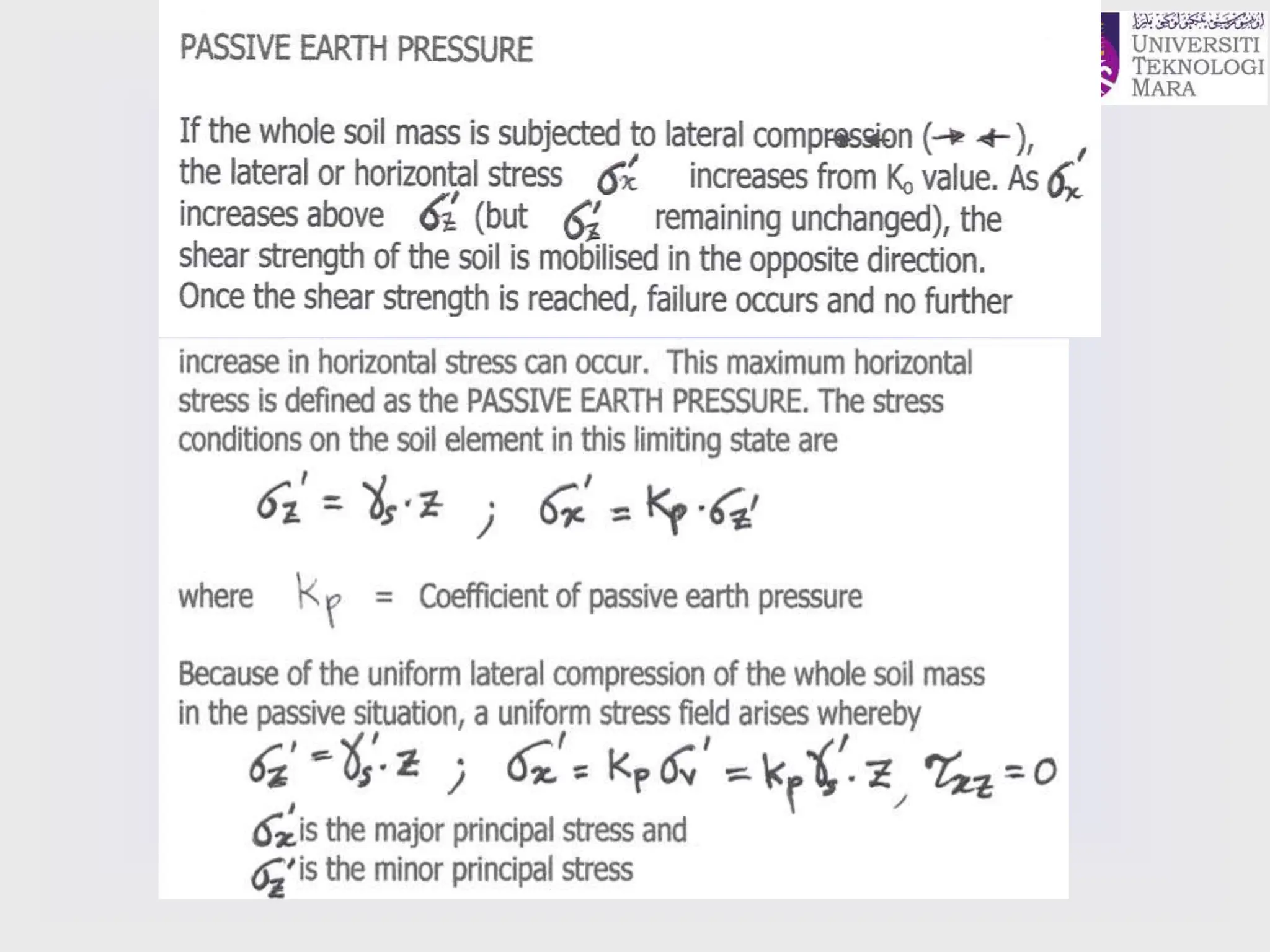
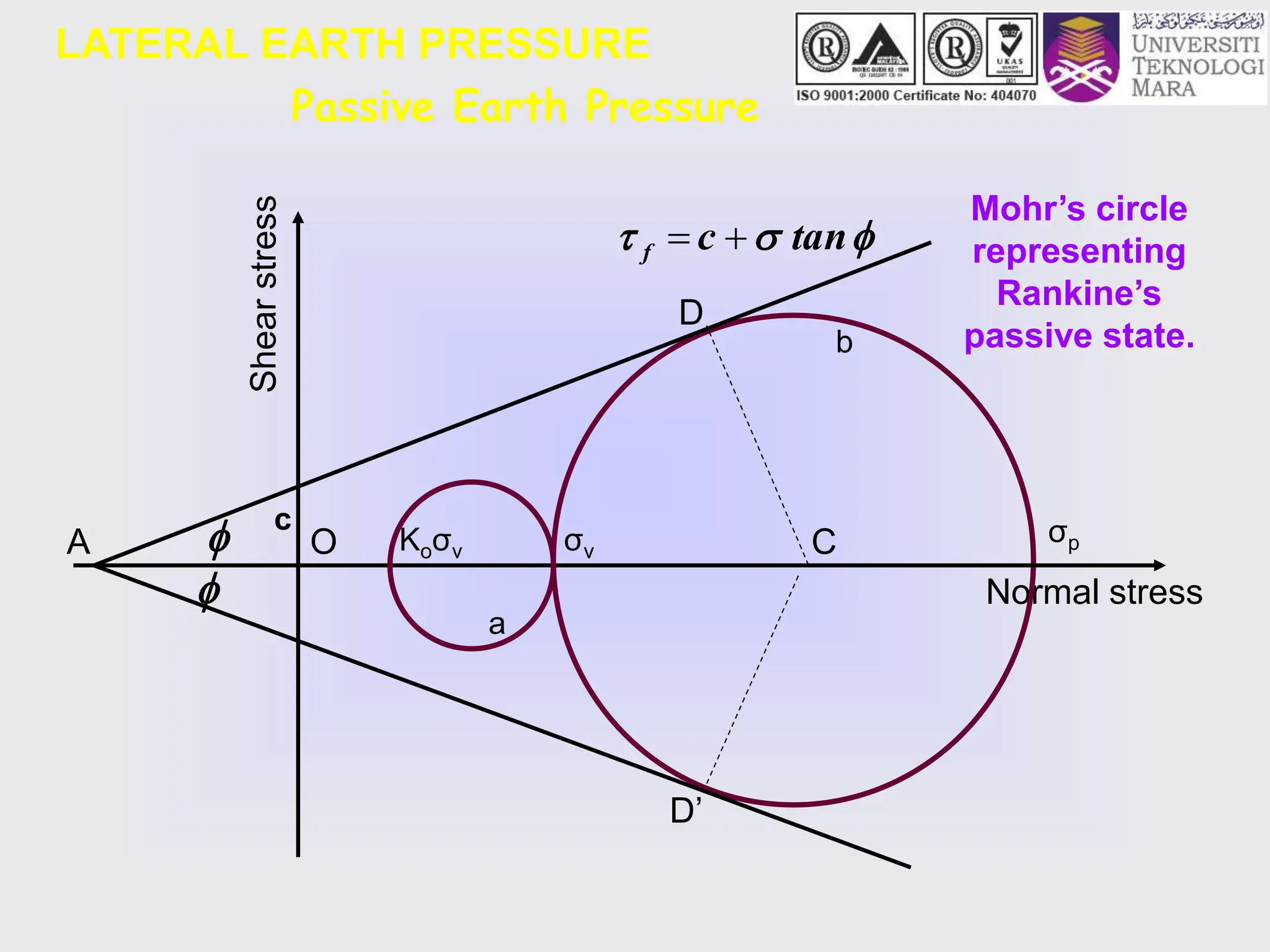
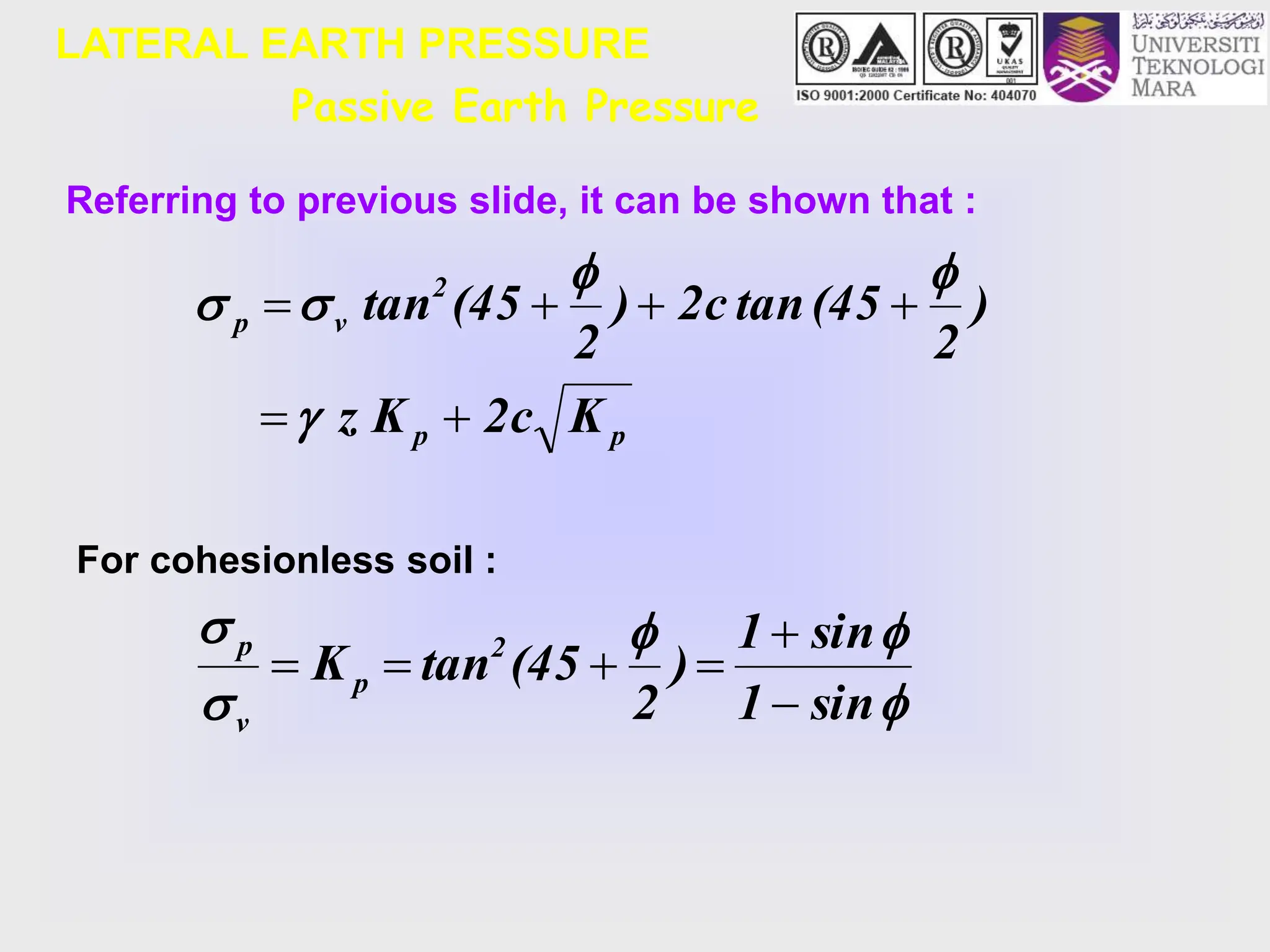
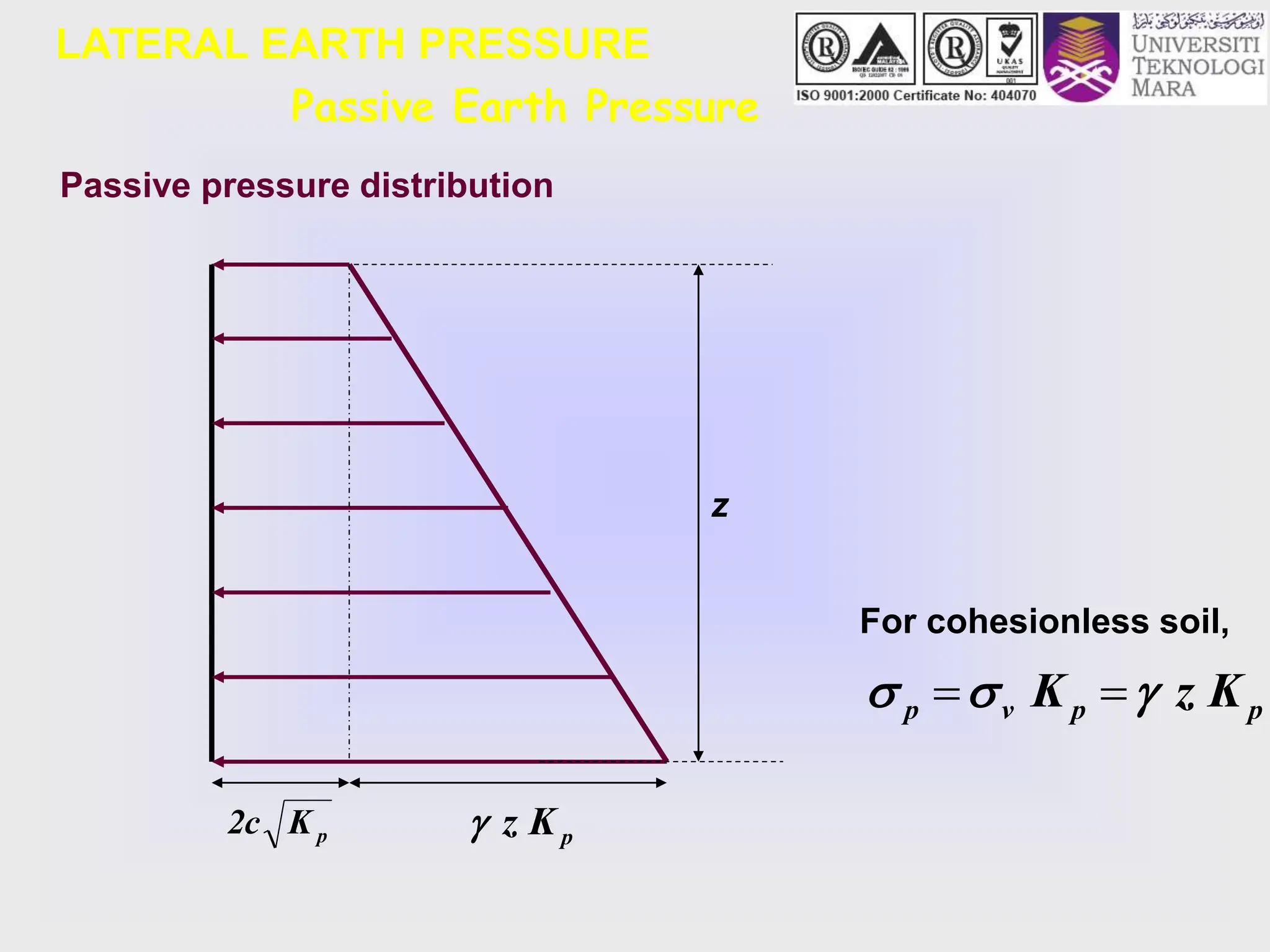
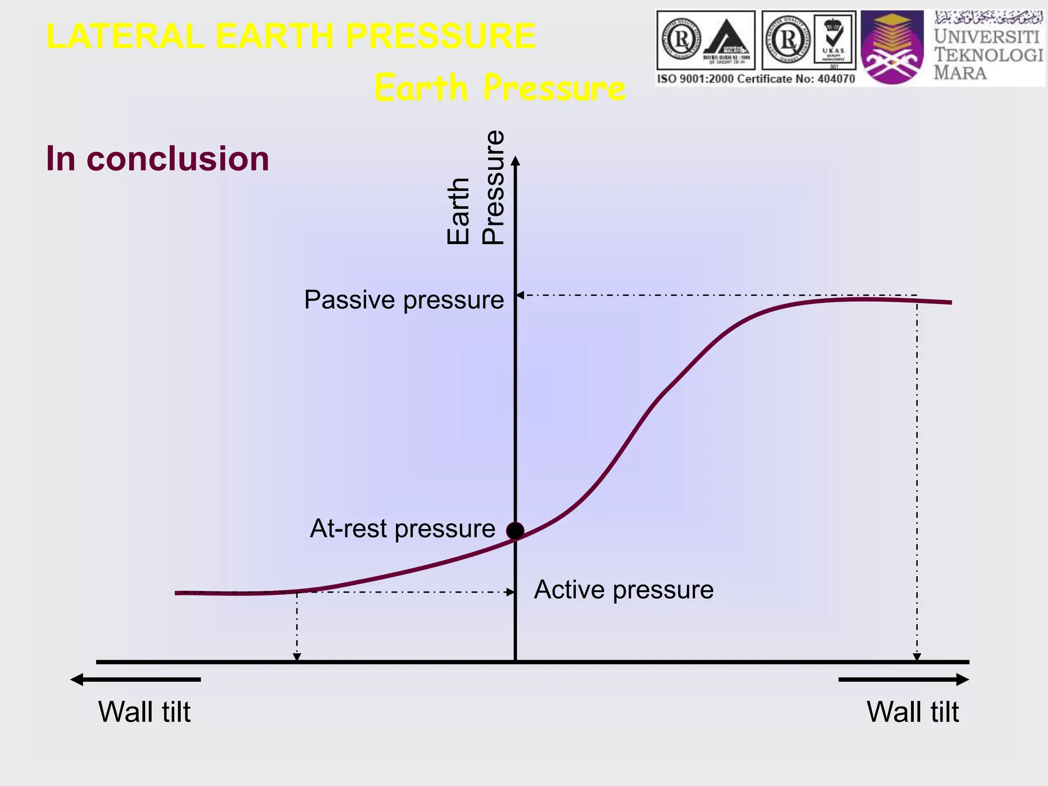
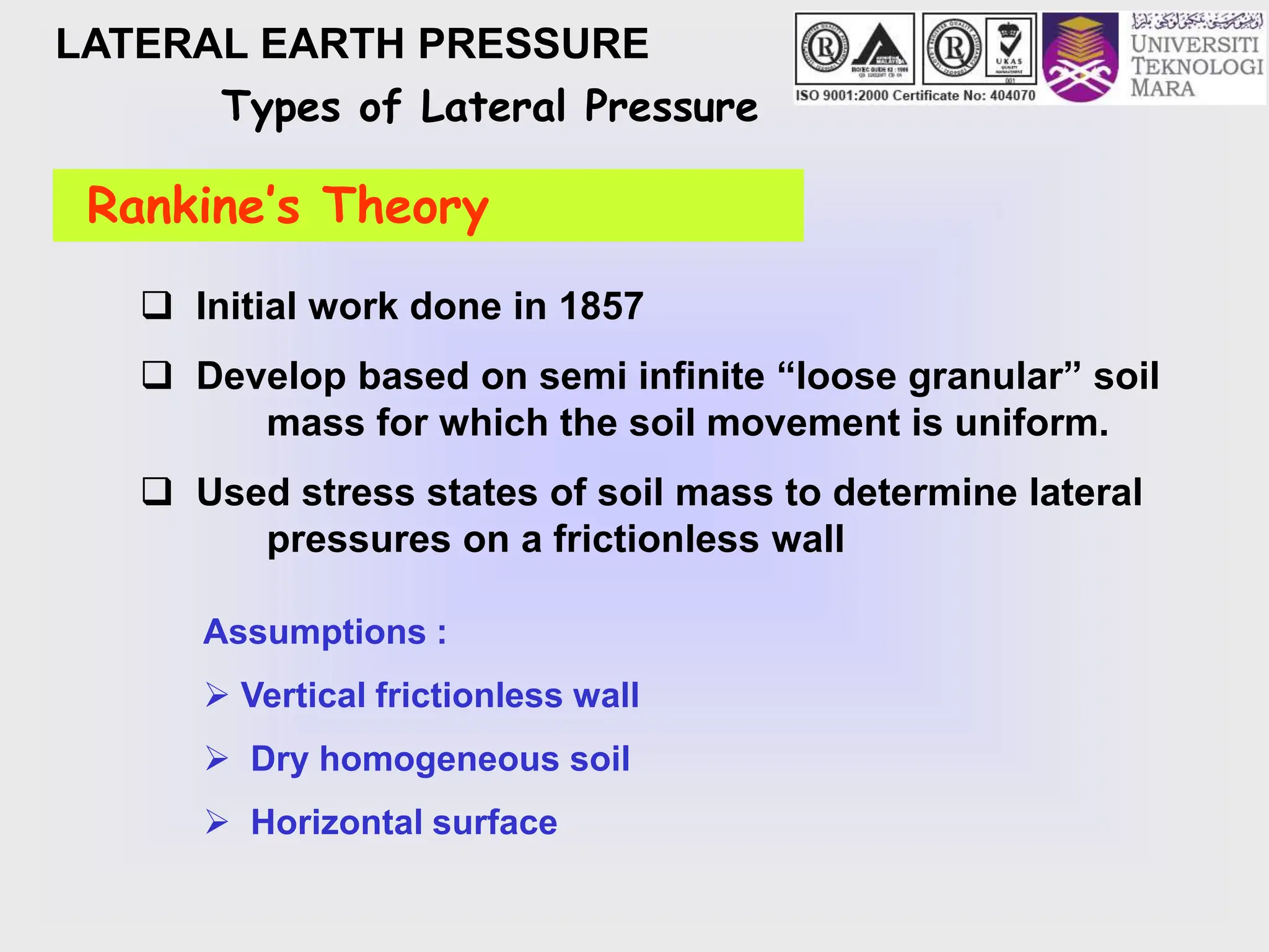
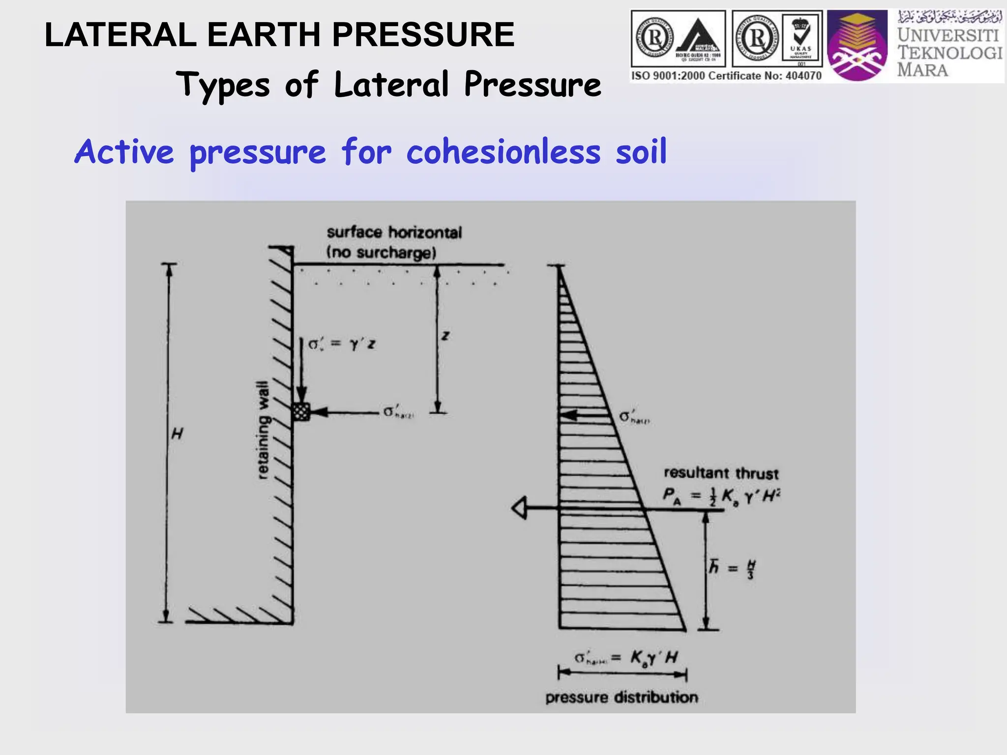
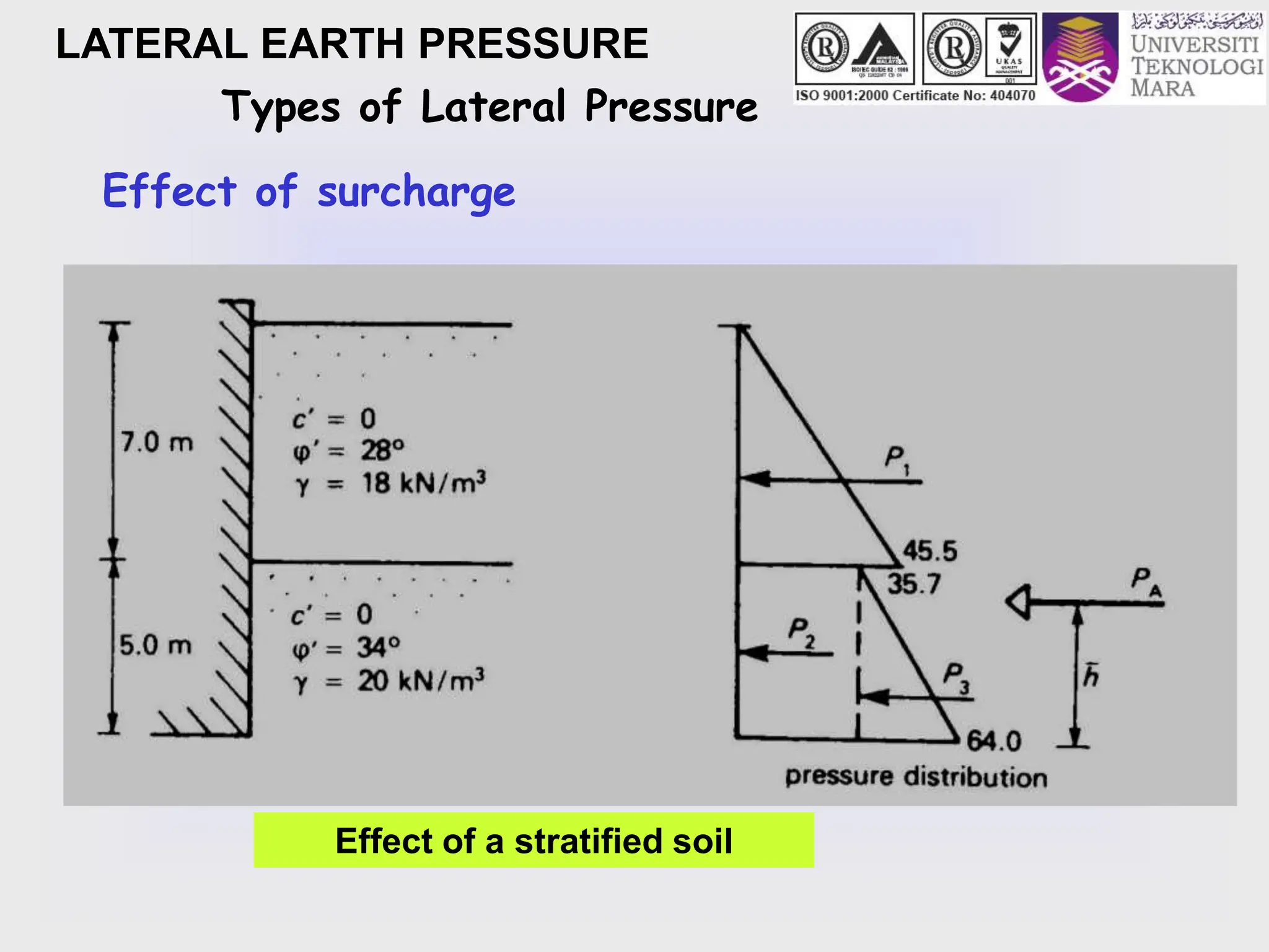
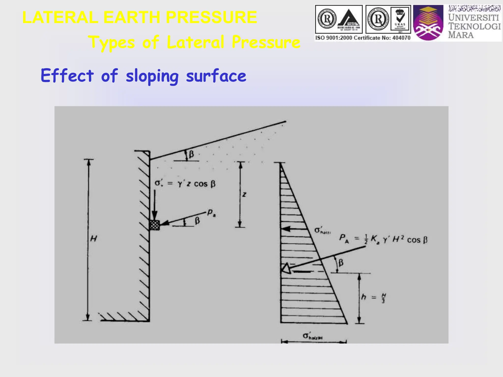
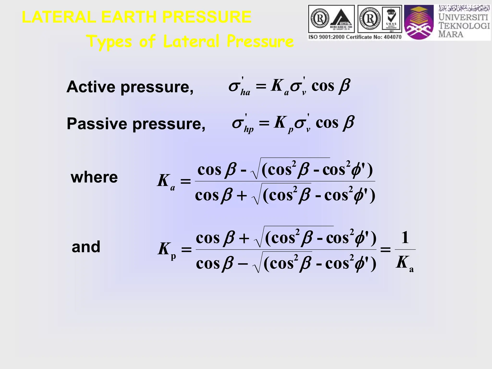
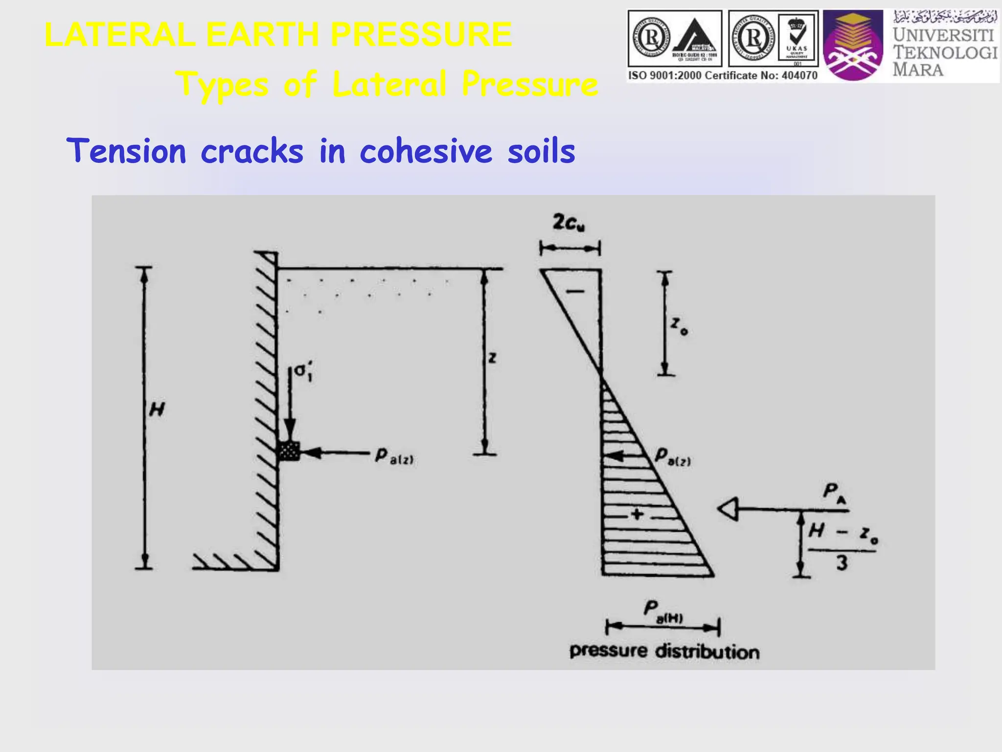
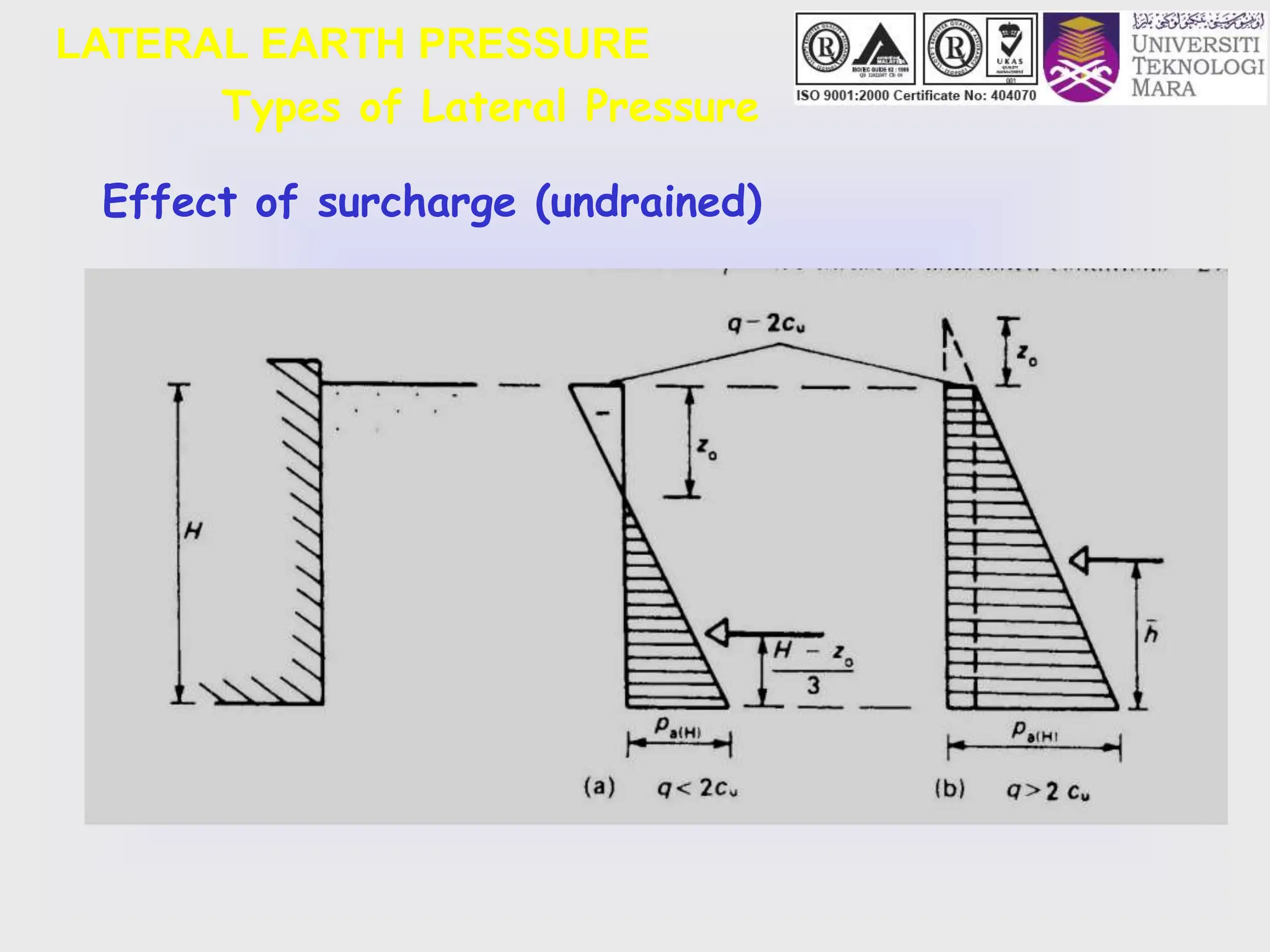
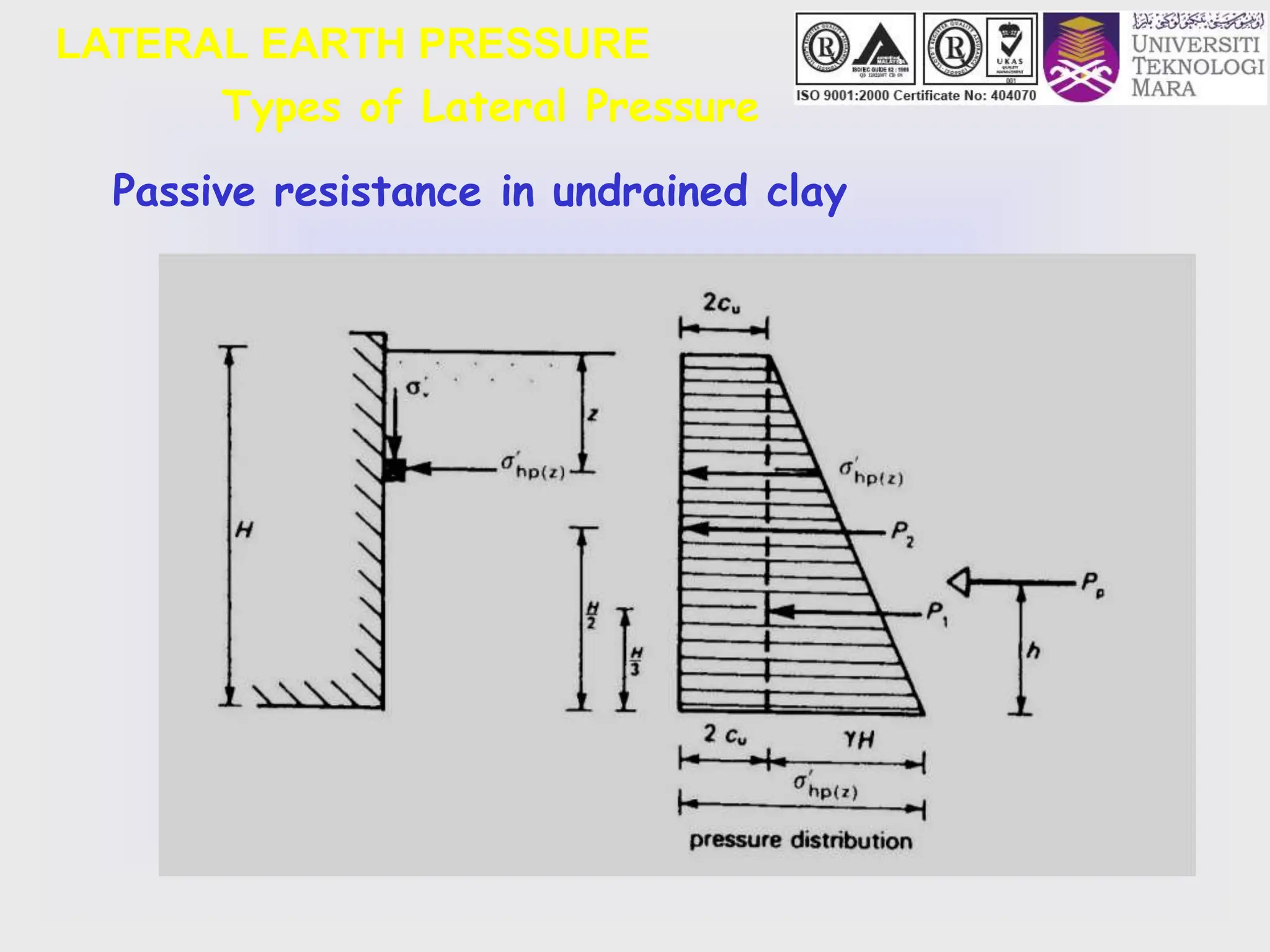
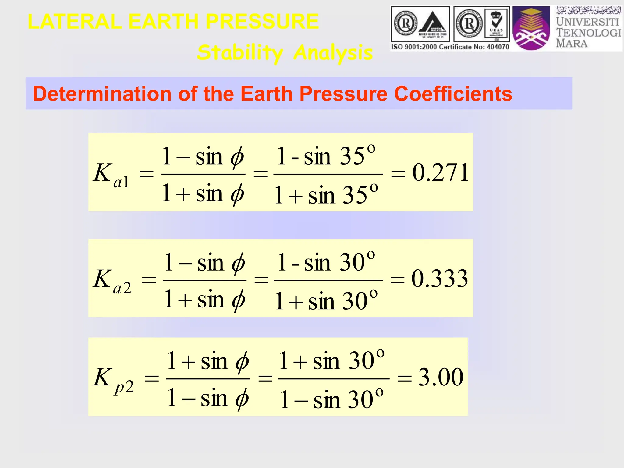
- The key lateral earth pressures of active, passive, and at-rest are defined based on Rankine's theory. Equations are provided for calculating the coefficient of pressure.
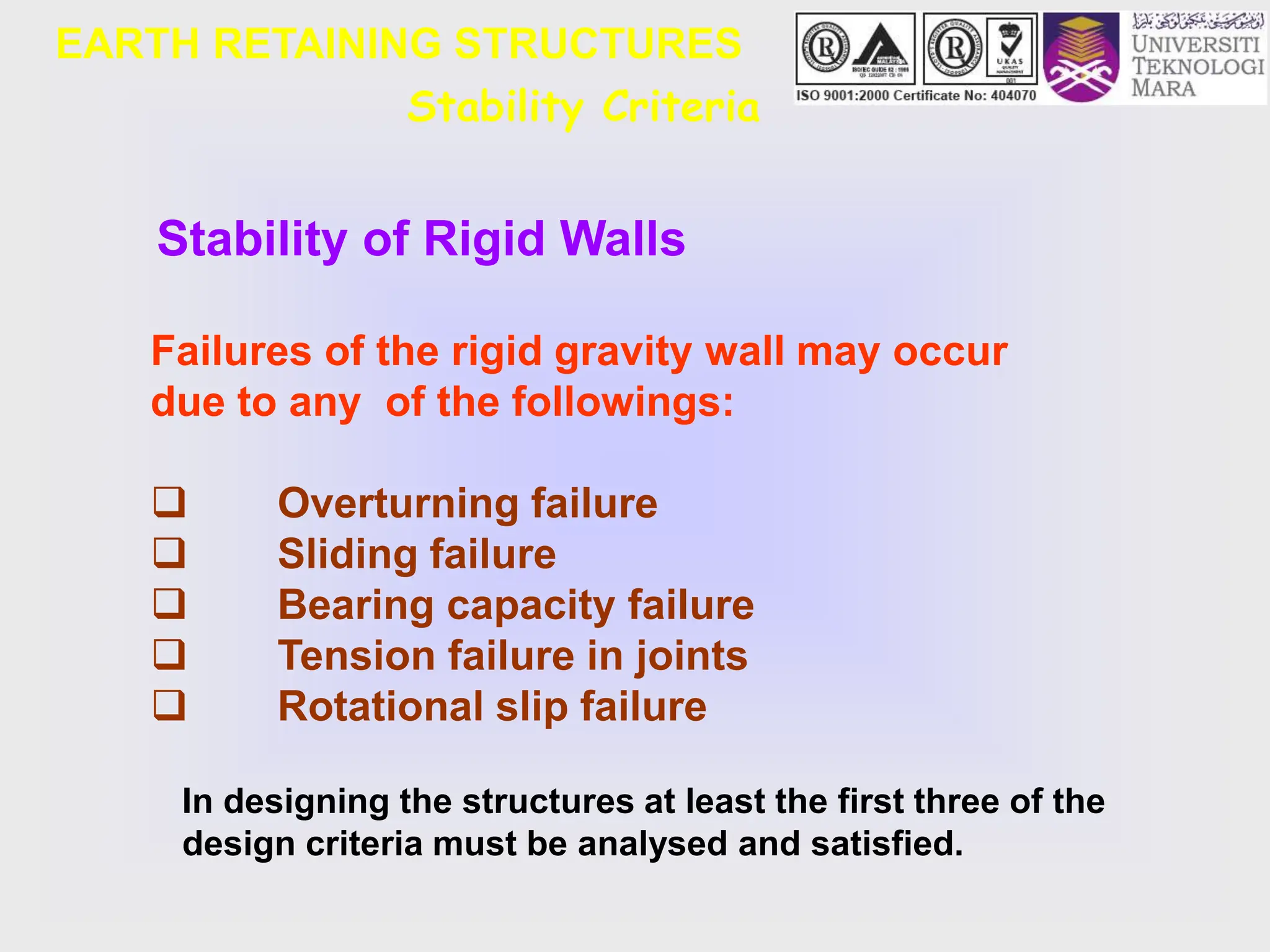
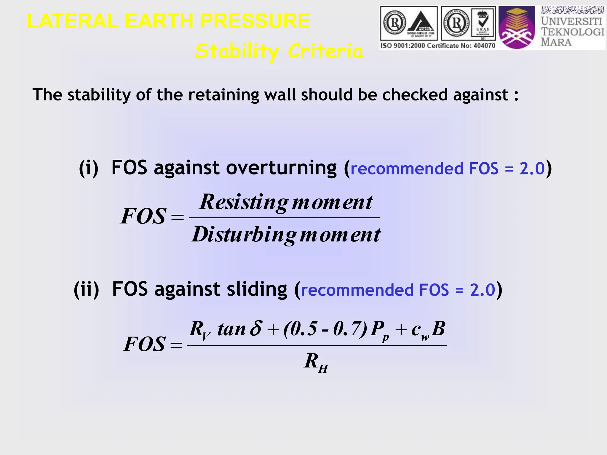
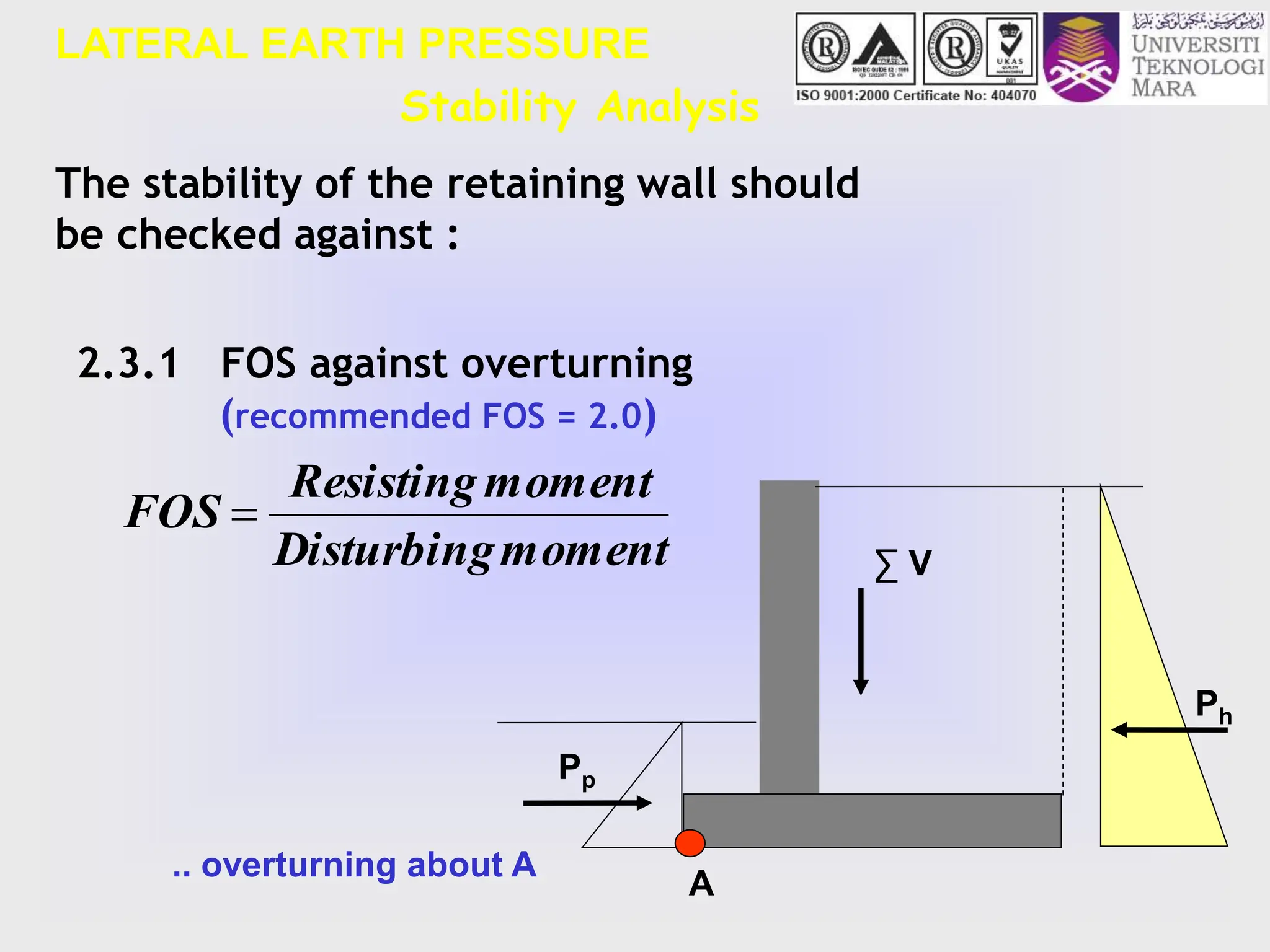
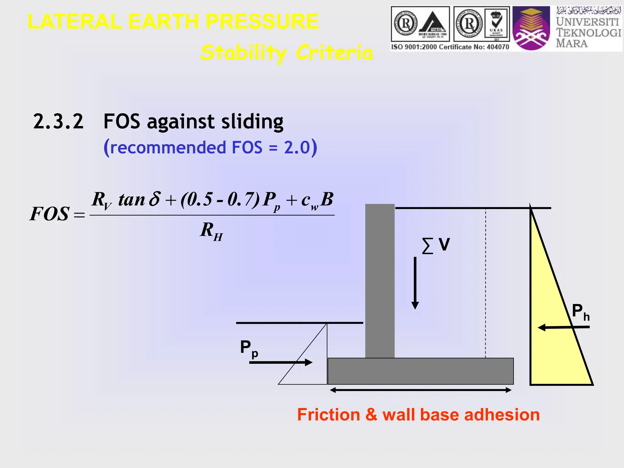
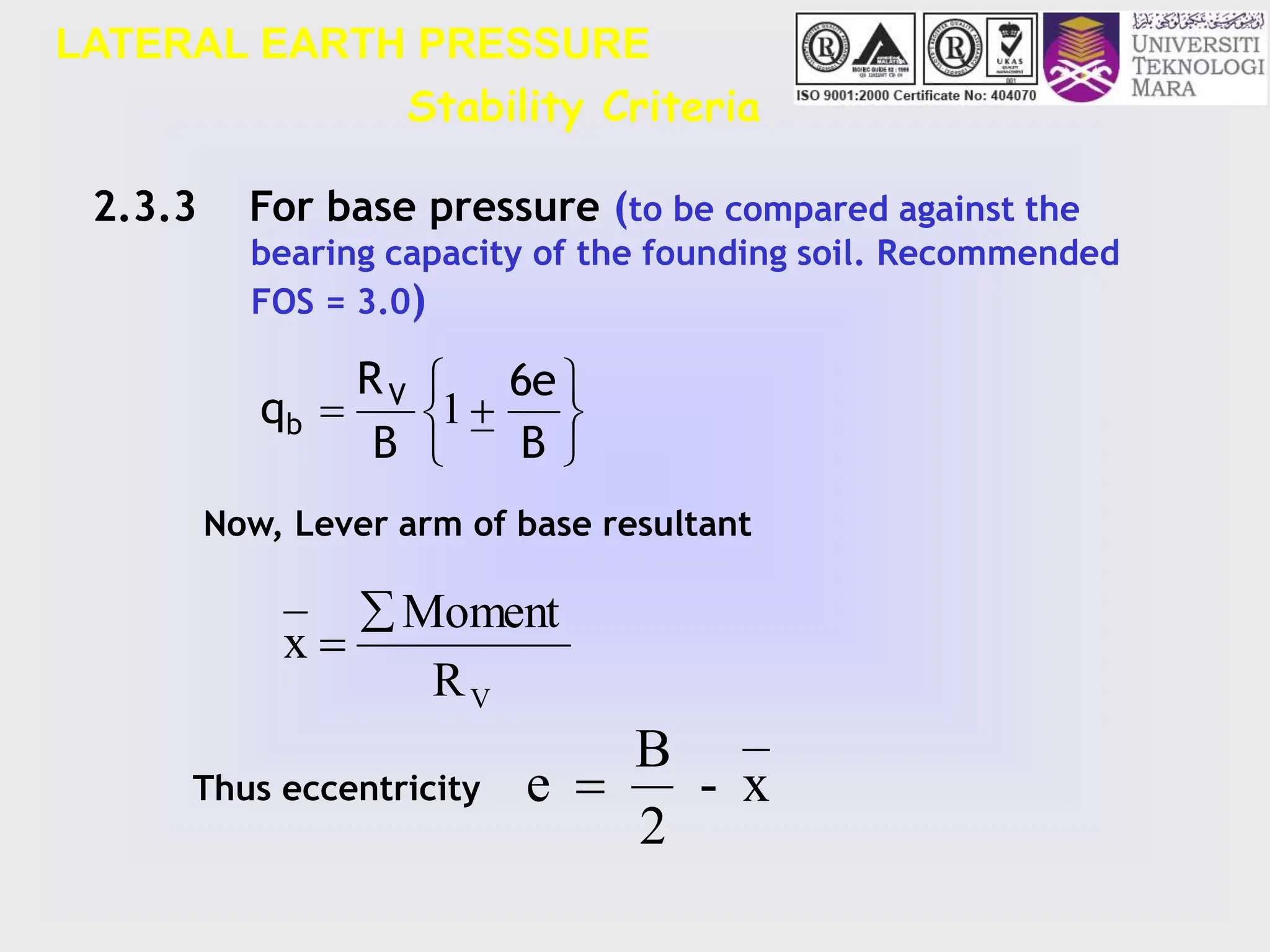
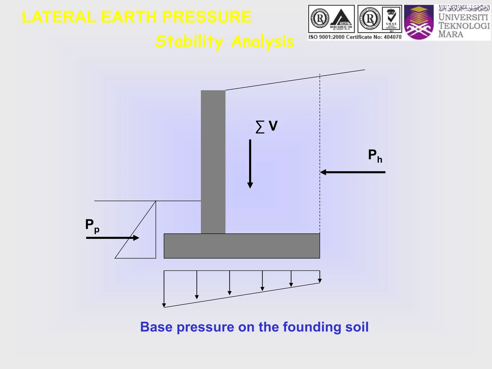
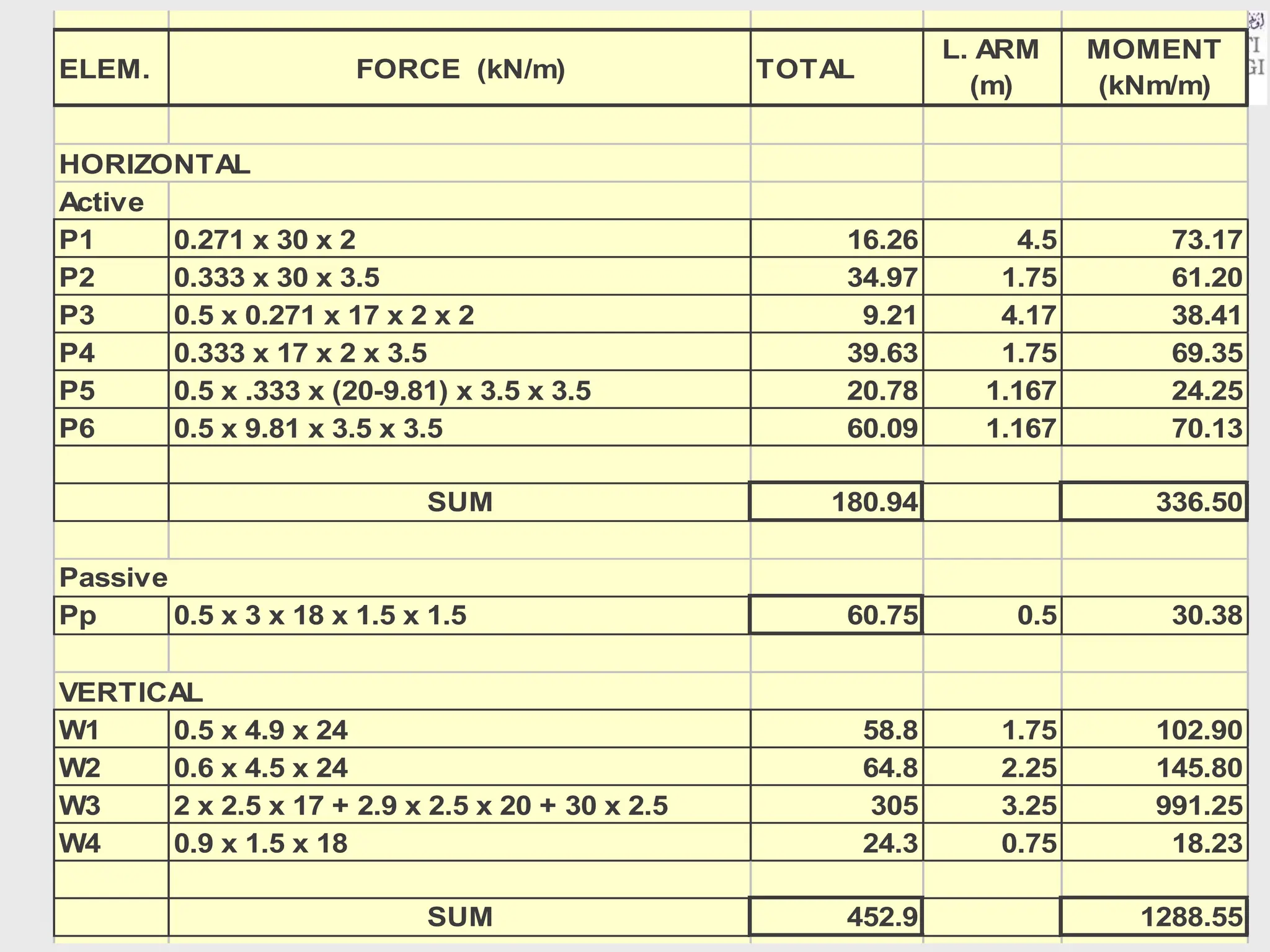
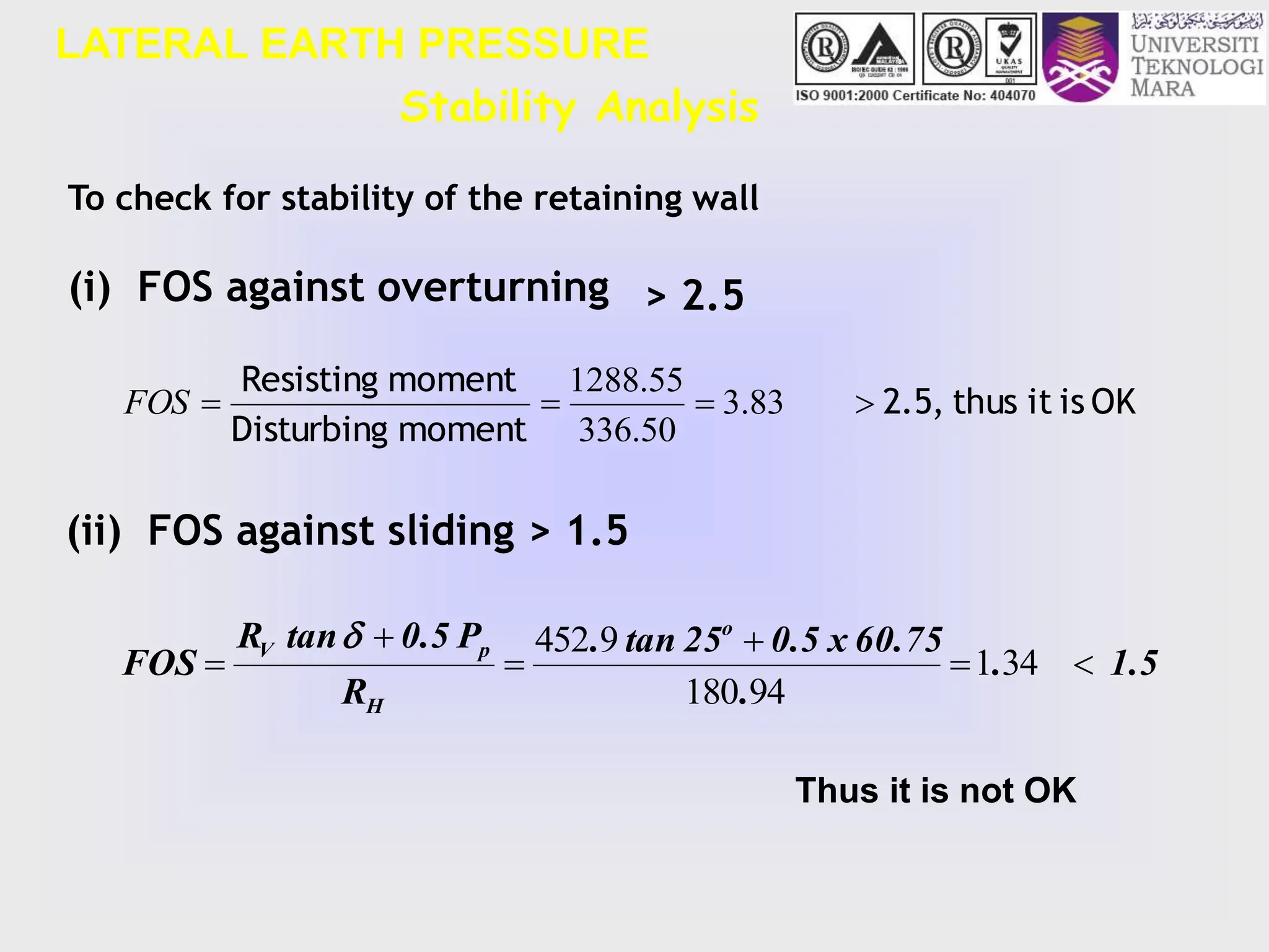
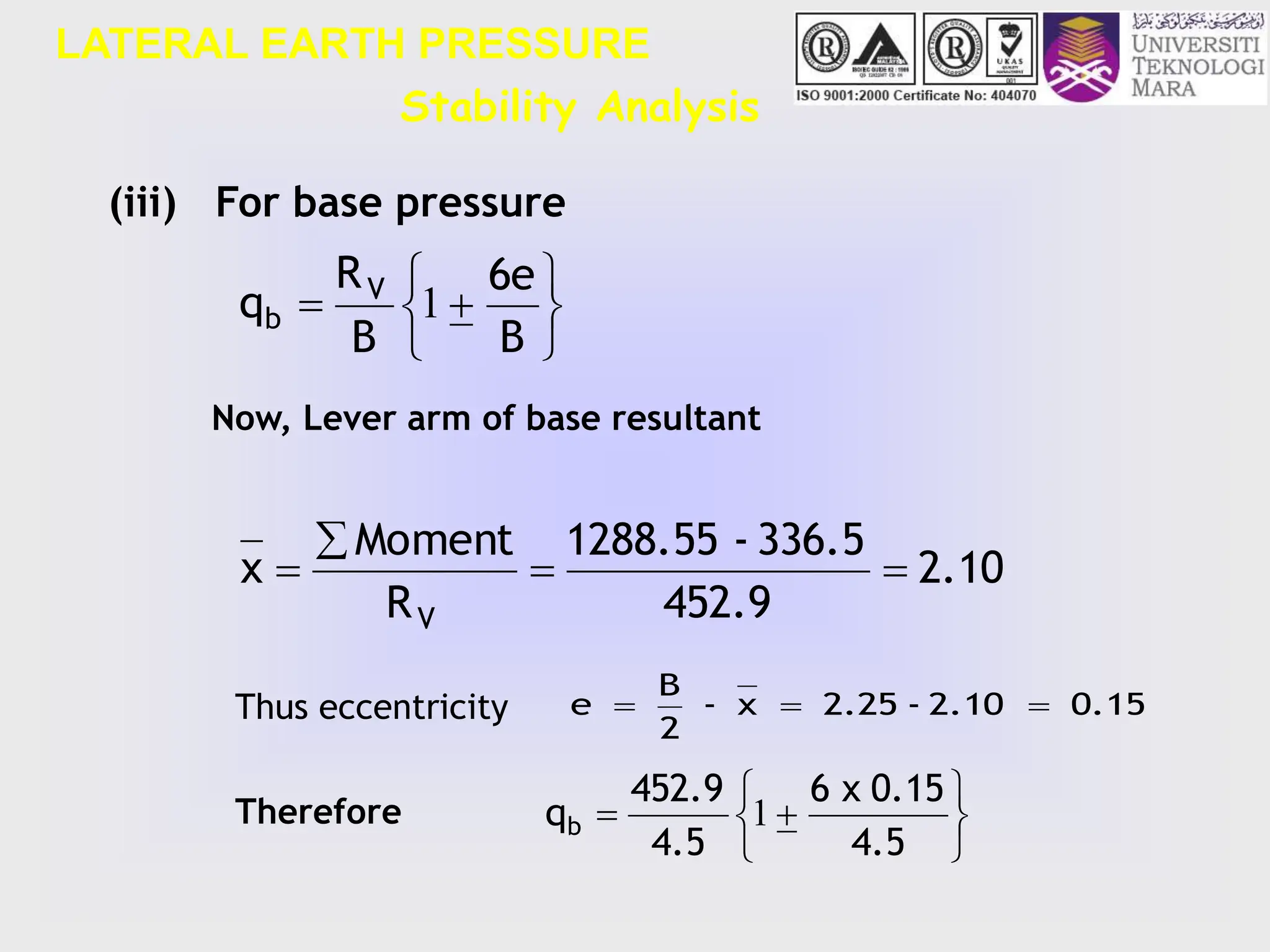
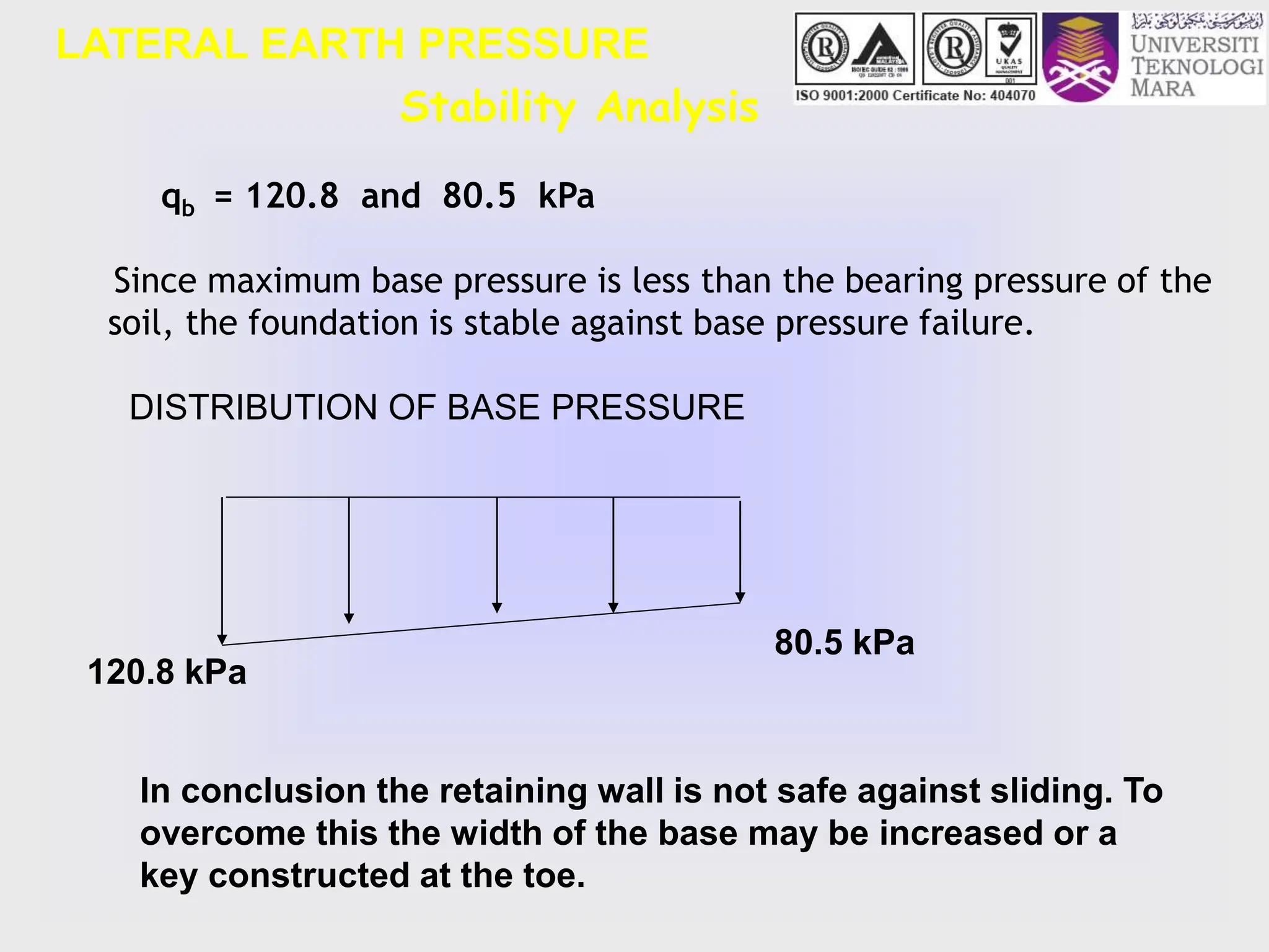
- Design criteria for stability are outlined, including checking factors of safety against overturning, sliding, and maximum base pressure.
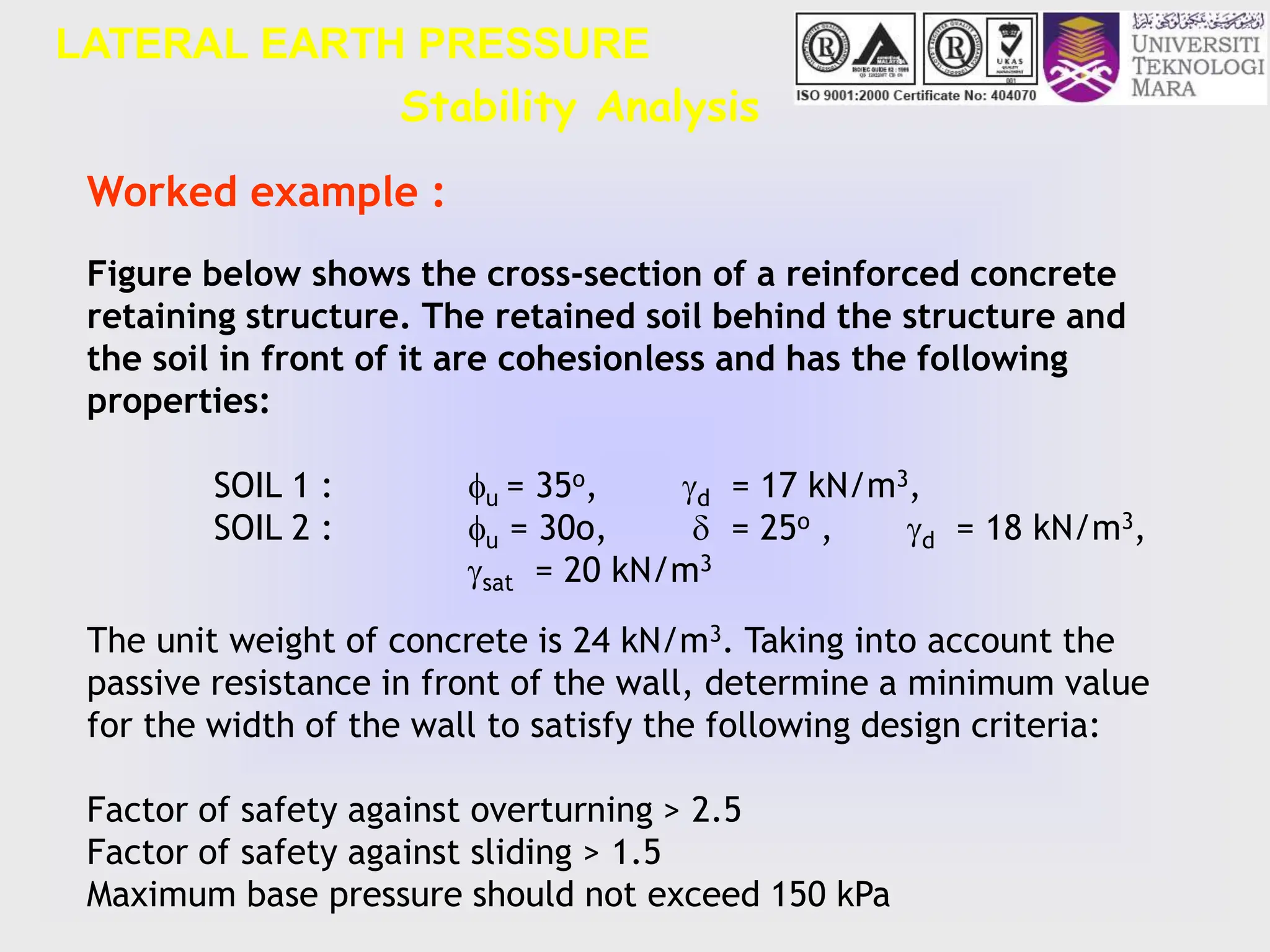
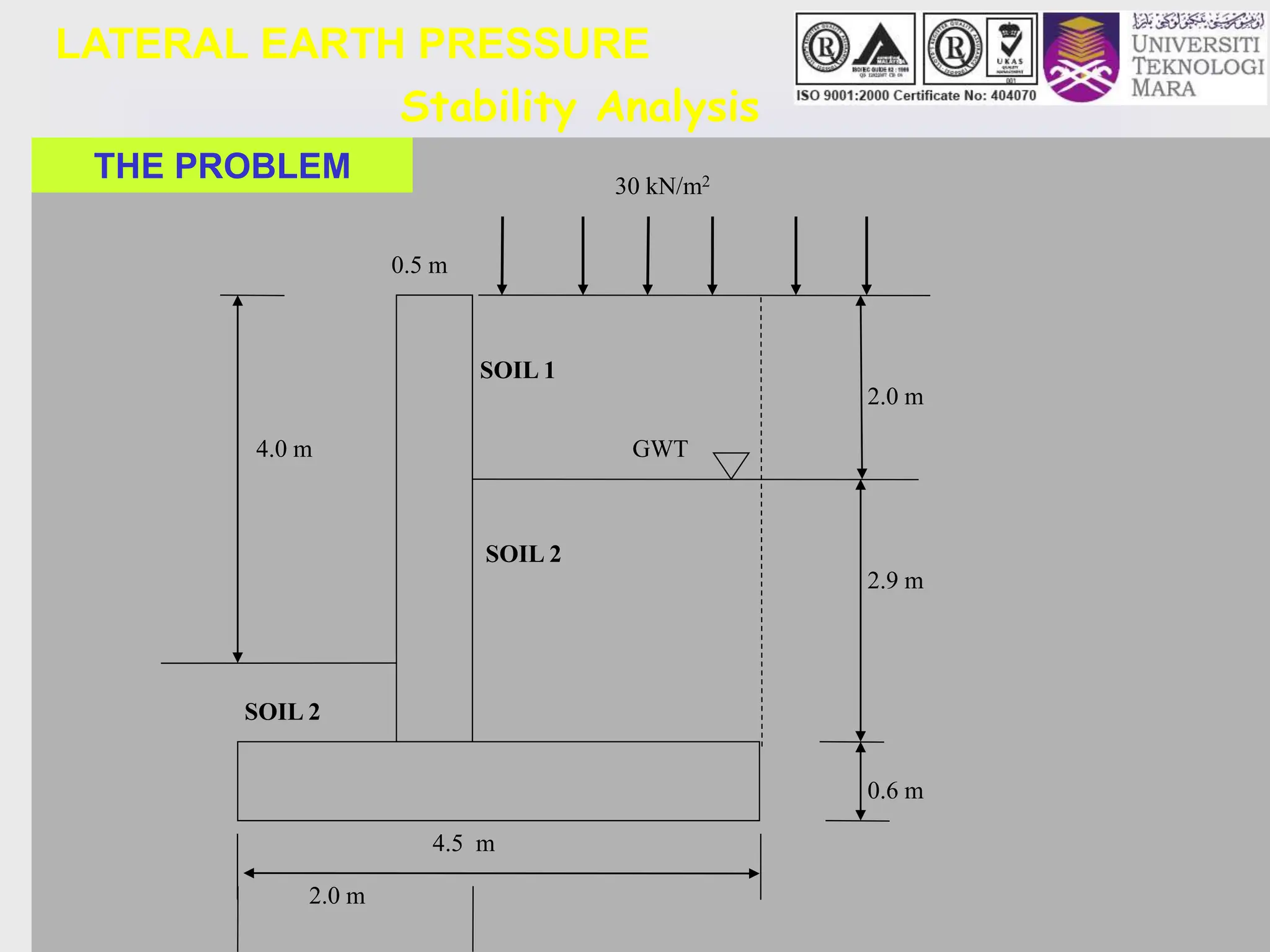
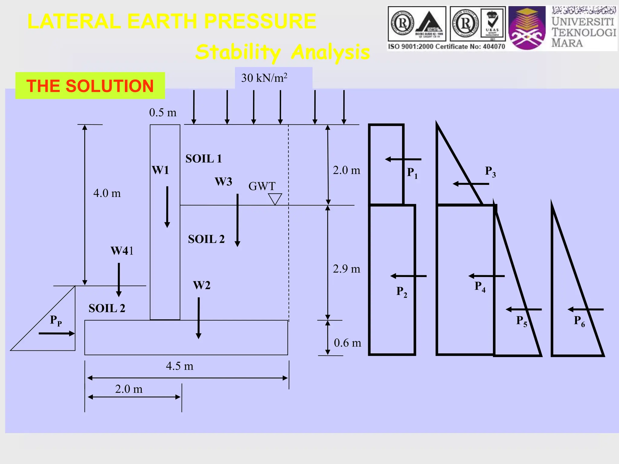
- An example problem is worked through to calculate the minimum width required for a reinforced concrete retaining wall


![Final_Year_Project_Review_01[1jvjnfghc].pptx](https://cdn.slidesharecdn.com/ss_thumbnails/finalyearprojectreview011-241004145646-fb8b76b9-thumbnail.jpg?width=640&height=640&fit=bounds)


