The slides presents Electronic AC Voltmeter, voltage follower rectifier voltmeter, precision rectifier voltmeter, precision rectifier amplifier voltmeter, voltage to current rectifier voltmeter, current measurement using voltmeter, voltage probe, current probe, temperature probe and RF probe
Guide to Power Supply Testing with MaxBotixMaxBotix Inc
Whether you believe your power supply may be faulty or you are doing routine
testing, it is important to verify the performance. Issues with a power supply can
limit the performance of your equipment, and it even has the potential to damage
your fine electronics. Proper and regular power supply testing can help minimize
this risk.
Power Quality Parameters Measurement Techniquesidescitation
Power quality (PQ) issue has attained considerable
attention in the last decade due to large penetration of power
electronics based loads and/or microprocessor based controlled
loads. On one hand these devices introduce power quality
problem and on other hand these mal-operate due to the
induced power quality problems. PQ disturbances/events cover
a broad frequency range with significantly different magnitude
variations and can be non-stationary, thus, accurate techniques
are required to identify and classify these events/disturbances.
This paper presents a comprehensive overview of different
techniques used for PQ events’ classifications, parameters.
Various artificial intelligent techniques which are used in
PQ event classification are also discussed. Major Key issues
and challenges in classifying PQ events are critically
examined and outlined. In this paper, the main Power Quality
(PQ) problems are presented with their associated causes and
consequences. The economic impacts associated with PQ are
characterized. Finally, some solutions to mitigate the PQ
problems are presented.
DESIGN AND IMPLEMENTATION OF A WIRELESS SENSOR AND ACTUATOR NETWORK FOR ENERG...ijesajournal
This paper describes the design, implementation, and testing of a wireless sensor and actuator network for monitoring the energy use of electric appliances in a home environment. The network includes energy measurement nodes and a central server, where the nodes read the energy use of connected appliance, and wirelessly report their readings to the central server for processing. The server displays the readings from
these nodes via a user visual interface in real time. Through this system, users can easily understand their electricity usage patterns and adapt their behaviour to reduce their energy consumption and costs. Moreover, users are able to remotely power on/off individual devices to actively control the power use of certain appliances. The system allows for inexpensive monitoring of home energy use and illustrates a practical way to control the energy consumption through user interaction.
An Intelligent Pressure Measurement Technique by Capacitance Pressure Sensor ...IDES Editor
Design of an intelligent pressure measurement
technique by Capacitance Pressure Sensor (CPS) using an
optimized Artificial Neural Network (ANN) is reported in this
paper. The objectives of the present work are: (i) to extend the
linearity range of measurement to 100% of input range, (ii)
make the measurement technique adaptive to variation in
physical parameters of diaphragm in CPS like, elasticity
modulus and thickness, permittivity of dielectric constant,
and temperature, and (iii) to achieve objectives (i) and (ii)
using an optimized neural network. A suitable optimal ANN
is added, replacing the conventional calibration circuit, in
cascade to data conversion unit. The proposed measurement
technique is tested considering variations in physical
parameters of CPS, and temperature. These parametric
variations are considered within the specified ranges. Results
show that the proposed intelligent technique has fulfilled the
objectives.
Question paper of Pre-University Examination of Electromagnetic Field Theory held at Guru Nanak Education Trust Group of Institution, Roorkee in EVEN Semester Session: 2012-13
Ammeter is a low resistance galvanometer
It is used to measure the current in a circuit in amperes
Galvanometer can be converted into an ammeter by using a low resistance wire in parallel with the galvanometer
the resistance of the wire depends upon the range of the ammeter
As shunt resistance is small the combined resistance of the galvanometer & the shunt is very low hence the ammeter has much lower resistance than galvanometer
An ideal ammeter has zero resistance
It is the most common instrument used to measure voltage
It measure either AC or DC voltage
It is a measure of the voltage between two points of an electrical current
This presentation discusses:
- Best practices regarding the need to ensure that all transformers used for metering circuits are properly sized
- The ability to optimize revenue regardless of customer usage over time
- Best practices to ensure that transformers and meters have been installed correctly in the field and continue to perform in the same fashion
- Best practices for certifying the accuracy class of the transformers and how to best set up a shop testing and field testing/verification program.
- What the costs of implementing such a system and what the costs of not implementing such a system can be.
1. Accurate Power Measurements
By Fred Francis, Owner Xenirad Broadcast Engineering
Power measurement in broadcasting has been a subject that too often leads engineers to make assumptions or leaves
them with questions not easily answered. As an engineering field service contractor I have had the opportunity to measure
power on many transmitters both radio and television and have found too many transmitters operating at a power level less than
is licensed.
Many stations have inline wattmeter’s external to the transmitter which can be very accurate or in many cases can be
very in-accurate. The elements in these units do go bad and can cause the meters to read significant errors. Calculating the
power output by efficiency is not an inherently accurate method as transmitter efficiency can vary over the life of the transmit-
ter or as a result of tube wear, tuning methodology, or antenna system condition. If you have significant VSWR your meter will
not read as accurately as with a properly functioning antenna system.
If however you have access to some test equipment described in this procedure you can calibrate your transmitters
metering and verify your external wattmeters readings. You will need either a spectrum analyzer with tracking generator or a
network analyzer and a power meter.
If you have an external wattmeter with a removable element you can get from the manufacturer of that meter a test
element that will provide a sample output on a BNC connector. The amount of sample varies with wattage and line size. This
element will provide a place to accurately measure your power if the following steps are taken. First you must determine what
the actual measured sample is. DO NOT simply go by the stated sample stamped on the element as the antenna condition will
cause this to vary. To do this you will need to disconnect your line from the transmitter and connect a test adapter to the line.
Next you will need either a network analyzer or a spectrum analyzer with a tracking generator. Calibrate your test equipment
according to manufacturer specifications. Generate a signal into the line as if it were the transmitter and measure the sampled
level at the test element. Write that number down in this example we will use –50db. Now to verify directionality of the test
coupler turn it around as if you were going to read reflected power and check it again. It should read >20db lower than the pre-
vious measurement, write that number down. Reconnect your transmitter back to your antenna and go back on the air.
Connect a power meter to that sample element and read the power when the element is facing toward your antenna.
As an example let’s say our transmitter is supposed to have a TPO of 20Kw which translates to 73.010dbm and we are reading
23.010dbm on the power meter and the sample measured –50dbm. 23.010+50=73.010 or 20KW. Now you can turn the element
around and measure the reflected power and calculate the VSWR based upon that reading. You now have accurate power meas-
urement data to calibrate your transmitters metering and you can verify that your external wattmeter is reading accurately. If the
reflected reads –7dbm+50=43.010dbm or a reflected power of 20 watts. An RF calculator that converts dbm to watts and vice
versa as well as VSWR calculations can be obtained free from Bird Electronics web page at
http://www.bird-technologies.com/en/Resources/TechnicalTools.aspx#.UsS0n_RDt8s
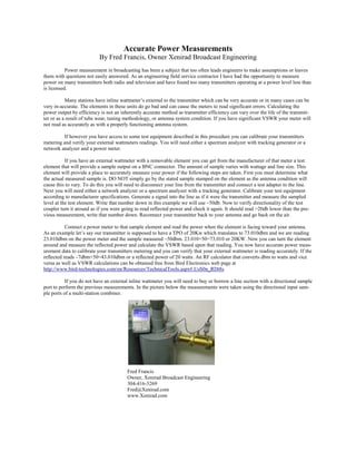
If you do not have an external inline wattmeter you will need to buy or borrow a line section with a directional sample
port to perform the previous measurements. In the picture below the measurements were taken using the directional input sam-
ple ports of a multi-station combiner.
Fred Francis
Owner, Xenirad Broadcast Engineering
304-416-3269
Fred@Xenirad.com
www.Xenirad.com