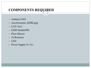
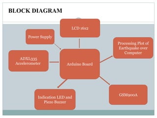
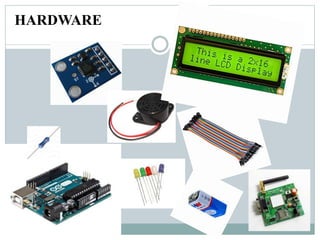
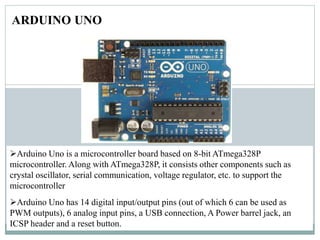
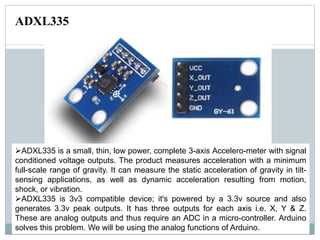
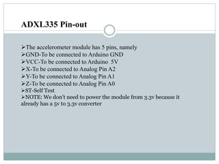
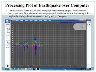
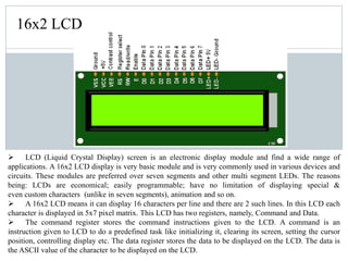
Earthquake Detection Social Network
using Arduino Board
B.E Semester 7th
(E.C Department)
Enroll No. Name.
150600111045 Punit Acharya
150600111043 Miraj Prajapati
150600111012 Kashif Khan
ABSTRACT
An earthquake is an unpredictable natural disaster that causes
damage to lives and property. It happens suddenly and we cannot
stop it but we can be alerted from it. In today’s time, there are many
technologies which can be used to detect the small shakes and knocks,
so that we can take precautions prior to some major vibrations in
earth. Earthquake detector is a device that detects earthquake shakes
Here we are using Accelerometer ADXL335 sensor to detect the pre-
earthquake vibrations. Accelerometer ADXL335 sensor is highly
sensitive. Here are Arduino is the brain of this detector, LCD is used
to display message and Led and buzzer is used as indicators.
COMPONENTS REQUIRED
 Arduino UNO
 Accelerometer ADXL335
 LCD 16x2
 GSM Module900
 Piezo Buzzer
 1k Resistors
 LED
 Power Supply 9v/12v
BLOCK DIAGRAM
ADXL335
Accelerometer
Processing Plot of
Earthquake over
Computer
Indication LED and
Piezo Buzzer
LCD 16x2
Power Supply
GSM900A
Arduino Board
HARDWARE
ARDUINO UNO
Arduino Uno is a microcontroller board based on 8-bit ATmega328P
microcontroller. Along with ATmega328P, it consists other components such as
crystal oscillator, serial communication, voltage regulator, etc. to support the
microcontroller
Arduino Uno has 14 digital input/output pins (out of which 6 can be used as
PWM outputs), 6 analog input pins, a USB connection, A Power barrel jack, an
ICSP header and a reset button.
FEATURES
Microcontroller: ATmega328
Operating Voltage: 5V
Input Voltage (recommended): 7-12V
Input Voltage (limits): 6-20V
Digital I/O Pins: 14 (of which 6 provide PWM output)
Analog Input Pins: 6
DC Current per I/O Pin: 40 mA
DC Current for 3.3V Pin: 50 mA
Flash Memory: 32 KB of which 0.5 KB used by boot loader
SRAM: 2 KB (ATmega328)
EEPROM: 1 KB (ATmega328)
Clock Speed: 16 MHz
ADXL335 is a small, thin, low power, complete 3-axis Accelero-meter with signal
conditioned voltage outputs. The product measures acceleration with a minimum
full-scale range of gravity. It can measure the static acceleration of gravity in tilt-
sensing applications, as well as dynamic acceleration resulting from motion,
shock, or vibration.
ADXL335 is 3v3 compatible device; it's powered by a 3.3v source and also
generates 3.3v peak outputs. It has three outputs for each axis i.e. X, Y & Z.
These are analog outputs and thus require an ADC in a micro-controller. Arduino
solves this problem. We will be using the analog functions of Arduino.
ADXL335
ADXL335 Pin-out
The accelerometer module has 5 pins, namely
GND-To be connected to Arduino GND
VCC-To be connected to Arduino 5V
X-To be connected to Analog Pin A2
Y-To be connected to Analog Pin A1
Z-To be connected to Analog Pin A0
ST-Self Test
NOTE: We don't need to power the module from 3.3v because it
already has a 5v to 3.3v converter
Processing Plot of Earthquake over Computer
 In this Arduino Earthquake Detection with Seismic Graph project, we have made
two codes: one for Arduino to detect an earthquake and another for Processing IDE
to plot the earthquake vibrations over the graph on Computer.
ANGLE OF INCLINATION
Angle of inclination means by how much angle the device is tilted from its plane of surface.
Angle of inclination are shown in below figure.
GSM MODERM
SIM900
GSM/GPRS Module
This is an ultra compact and reliable wireless module. The SIM900A is a
complete Dual-band GSM/GPRS solution in a SMT module which can be
embedded in the customer applications allowing you to benefit from small
dimensions and cost-effective solutions. Featuring an industry-standard interface,
the SIM900A delivers GSM/GPRS 900/1800MHz performance for voice, SMS,
Data, and Fax in a small form factor and with low power consumption. With a tiny
configuration of 24mm x 24mm x 3 mm, SIM900A can fit almost all the space
requirements in your applications.
FEATURES
 Dual-Band GSM/GPRS 900/ 1800 MHz
 RS232 interface for direct communication with computer
 Configurable baud rate from 9600-115200bps
 Wire Antenna ( SMA connector with GSM Antenna Optional )
 SIM Card holder.
 Built in Network Status LED
 Inbuilt Powerful TCP/IP protocol stack for internet data transfer over GPRS.
 Normal operation temperature: -20 °C to +55 °C
 Input Voltage: 12V DC
16x2 LCD
 LCD (Liquid Crystal Display) screen is an electronic display module and find a wide range of
applications. A 16x2 LCD display is very basic module and is very commonly used in various devices and
circuits. These modules are preferred over seven segments and other multi segment LEDs. The reasons
being: LCDs are economical; easily programmable; have no limitation of displaying special &
even custom characters (unlike in seven segments), animation and so on.
 A 16x2 LCD means it can display 16 characters per line and there are 2 such lines. In this LCD each
character is displayed in 5x7 pixel matrix. This LCD has two registers, namely, Command and Data.
 The command register stores the command instructions given to the LCD. A command is an
instruction given to LCD to do a predefined task like initializing it, clearing its screen, setting the cursor
position, controlling display etc. The data register stores the data to be displayed on the LCD. The data is
the ASCII value of the character to be displayed on the LCD.
ADVANTAGE
 When the Earthquake alerting message received by the Fire brigade and
NDRF teams. They alerting peoples bye Radios and starts rescue so the
disaster effect are reduced and the causality of destroying construction is
less and save the peoples life.
DISADVANTAGE
 When the sometimes the first safety alarm is not working properly. The
systems are not work proper. when the causality of the disaster is more
because we have not alerting them and the destroyed the all the
constructions who worked the newly.
 When on some construction sites. The constructions are destroyed by very
fast and the destroyed construction sensitivity is very high. then the alarm
not work properly and the safety teams and rescue teams are started the
work. But actually not happen anything on this place so this is the total
waste of time.
Thank you

Earthquake detection social networking

  • 1.
    Earthquake Detection SocialNetwork using Arduino Board B.E Semester 7th (E.C Department) Enroll No. Name. 150600111045 Punit Acharya 150600111043 Miraj Prajapati 150600111012 Kashif Khan
  • 2.
    ABSTRACT An earthquake isan unpredictable natural disaster that causes damage to lives and property. It happens suddenly and we cannot stop it but we can be alerted from it. In today’s time, there are many technologies which can be used to detect the small shakes and knocks, so that we can take precautions prior to some major vibrations in earth. Earthquake detector is a device that detects earthquake shakes Here we are using Accelerometer ADXL335 sensor to detect the pre- earthquake vibrations. Accelerometer ADXL335 sensor is highly sensitive. Here are Arduino is the brain of this detector, LCD is used to display message and Led and buzzer is used as indicators.
  • 3.
    COMPONENTS REQUIRED  ArduinoUNO  Accelerometer ADXL335  LCD 16x2  GSM Module900  Piezo Buzzer  1k Resistors  LED  Power Supply 9v/12v
  • 4.
    BLOCK DIAGRAM ADXL335 Accelerometer Processing Plotof Earthquake over Computer Indication LED and Piezo Buzzer LCD 16x2 Power Supply GSM900A Arduino Board
  • 5.
  • 6.
    ARDUINO UNO Arduino Unois a microcontroller board based on 8-bit ATmega328P microcontroller. Along with ATmega328P, it consists other components such as crystal oscillator, serial communication, voltage regulator, etc. to support the microcontroller Arduino Uno has 14 digital input/output pins (out of which 6 can be used as PWM outputs), 6 analog input pins, a USB connection, A Power barrel jack, an ICSP header and a reset button.
  • 7.
    FEATURES Microcontroller: ATmega328 Operating Voltage:5V Input Voltage (recommended): 7-12V Input Voltage (limits): 6-20V Digital I/O Pins: 14 (of which 6 provide PWM output) Analog Input Pins: 6 DC Current per I/O Pin: 40 mA DC Current for 3.3V Pin: 50 mA Flash Memory: 32 KB of which 0.5 KB used by boot loader SRAM: 2 KB (ATmega328) EEPROM: 1 KB (ATmega328) Clock Speed: 16 MHz
  • 8.
    ADXL335 is asmall, thin, low power, complete 3-axis Accelero-meter with signal conditioned voltage outputs. The product measures acceleration with a minimum full-scale range of gravity. It can measure the static acceleration of gravity in tilt- sensing applications, as well as dynamic acceleration resulting from motion, shock, or vibration. ADXL335 is 3v3 compatible device; it's powered by a 3.3v source and also generates 3.3v peak outputs. It has three outputs for each axis i.e. X, Y & Z. These are analog outputs and thus require an ADC in a micro-controller. Arduino solves this problem. We will be using the analog functions of Arduino. ADXL335
  • 9.
    ADXL335 Pin-out The accelerometermodule has 5 pins, namely GND-To be connected to Arduino GND VCC-To be connected to Arduino 5V X-To be connected to Analog Pin A2 Y-To be connected to Analog Pin A1 Z-To be connected to Analog Pin A0 ST-Self Test NOTE: We don't need to power the module from 3.3v because it already has a 5v to 3.3v converter
  • 10.
    Processing Plot ofEarthquake over Computer  In this Arduino Earthquake Detection with Seismic Graph project, we have made two codes: one for Arduino to detect an earthquake and another for Processing IDE to plot the earthquake vibrations over the graph on Computer.
  • 11.
    ANGLE OF INCLINATION Angleof inclination means by how much angle the device is tilted from its plane of surface. Angle of inclination are shown in below figure.
  • 12.
  • 13.
    SIM900 GSM/GPRS Module This isan ultra compact and reliable wireless module. The SIM900A is a complete Dual-band GSM/GPRS solution in a SMT module which can be embedded in the customer applications allowing you to benefit from small dimensions and cost-effective solutions. Featuring an industry-standard interface, the SIM900A delivers GSM/GPRS 900/1800MHz performance for voice, SMS, Data, and Fax in a small form factor and with low power consumption. With a tiny configuration of 24mm x 24mm x 3 mm, SIM900A can fit almost all the space requirements in your applications.
  • 14.
    FEATURES  Dual-Band GSM/GPRS900/ 1800 MHz  RS232 interface for direct communication with computer  Configurable baud rate from 9600-115200bps  Wire Antenna ( SMA connector with GSM Antenna Optional )  SIM Card holder.  Built in Network Status LED  Inbuilt Powerful TCP/IP protocol stack for internet data transfer over GPRS.  Normal operation temperature: -20 °C to +55 °C  Input Voltage: 12V DC
  • 15.
    16x2 LCD  LCD(Liquid Crystal Display) screen is an electronic display module and find a wide range of applications. A 16x2 LCD display is very basic module and is very commonly used in various devices and circuits. These modules are preferred over seven segments and other multi segment LEDs. The reasons being: LCDs are economical; easily programmable; have no limitation of displaying special & even custom characters (unlike in seven segments), animation and so on.  A 16x2 LCD means it can display 16 characters per line and there are 2 such lines. In this LCD each character is displayed in 5x7 pixel matrix. This LCD has two registers, namely, Command and Data.  The command register stores the command instructions given to the LCD. A command is an instruction given to LCD to do a predefined task like initializing it, clearing its screen, setting the cursor position, controlling display etc. The data register stores the data to be displayed on the LCD. The data is the ASCII value of the character to be displayed on the LCD.
  • 16.
    ADVANTAGE  When theEarthquake alerting message received by the Fire brigade and NDRF teams. They alerting peoples bye Radios and starts rescue so the disaster effect are reduced and the causality of destroying construction is less and save the peoples life.
  • 17.
    DISADVANTAGE  When thesometimes the first safety alarm is not working properly. The systems are not work proper. when the causality of the disaster is more because we have not alerting them and the destroyed the all the constructions who worked the newly.  When on some construction sites. The constructions are destroyed by very fast and the destroyed construction sensitivity is very high. then the alarm not work properly and the safety teams and rescue teams are started the work. But actually not happen anything on this place so this is the total waste of time.
  • 18.