This document summarizes how beams and columns in reinforced concrete (RC) buildings resist earthquakes. It discusses the reinforcement and design strategies for beams and columns.
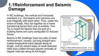
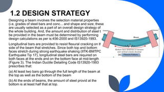
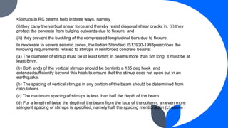
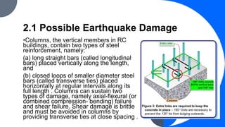
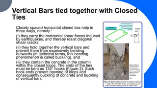
For beams, it describes the longitudinal bars and stirrups that provide flexural strength and resist shear cracks. The design focuses on placement of steel to resist stretching on both faces. Columns use longitudinal bars and transverse ties to resist axial and shear stresses. The design aims to prevent shear failure through close spacing of ties. Reinforcement details like hook ends and lap lengths are specified to improve ductility.