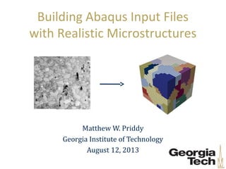
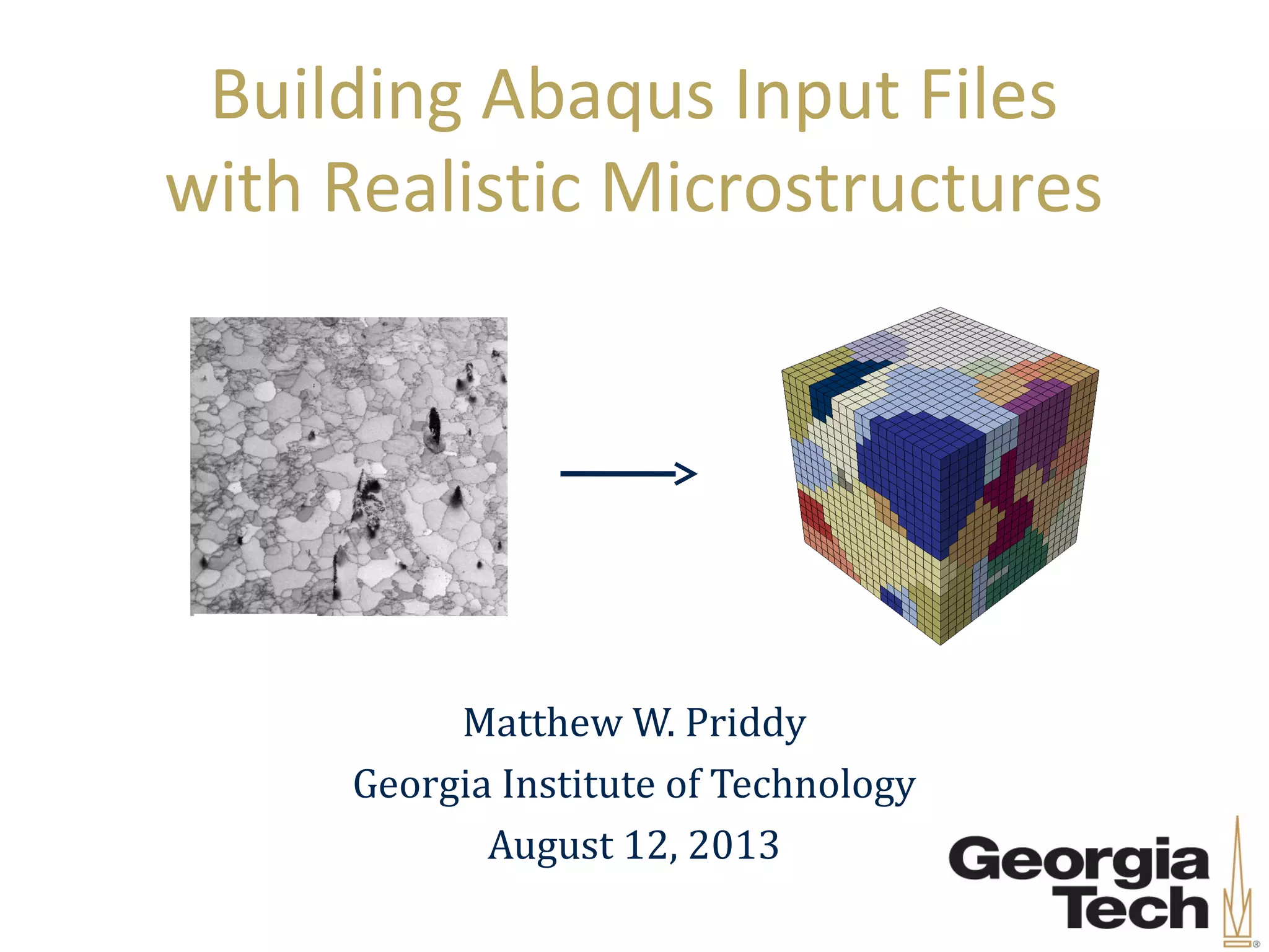
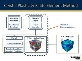
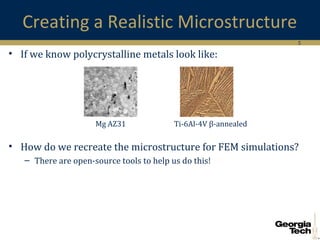
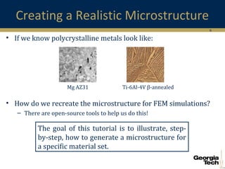
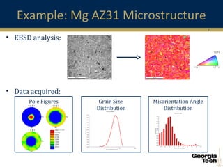
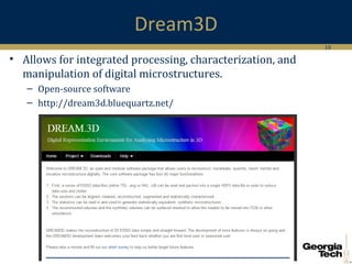
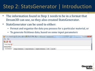
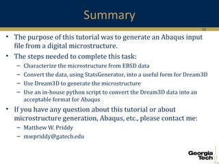
Building Abaqus Input Files
with Realistic Microstructures
Matthew W. Priddy
Georgia Institute of Technology
August 12, 2013
2
Outline
• Introduction
• Mg AZ31 Abaqus Input file generation
– Step 1: EBSD
– Step 2: StatsGenerator
– Step 3: Dream3D
– Step 4: Python
• Summary
3
Crystal Plasticity Finite Element Method
CPFEM Results
Polycrystalline MeshUMAT
Material
Input
Mesh
Generator
Loading Conditions
Boundary Conditions
Abaqus/Standard
Kinematic
Equations
Constitutive
Equations
4
Crystal Plasticity Finite Element Method
CPFEM Results
Polycrystalline MeshUMAT
Material
Input
Mesh
Generator
Loading Conditions
Boundary Conditions
Abaqus/Standard
Kinematic
Equations
Constitutive
Equations
The focus of
this presentation
5
Creating a Realistic Microstructure
• If we know polycrystalline metals look like:
• How do we recreate the microstructure for FEM simulations?
– There are open-source tools to help us do this!
Ti-6Al-4V β-annealedMg AZ31
6
Creating a Realistic Microstructure
• If we know polycrystalline metals look like:
• How do we recreate the microstructure for FEM simulations?
– There are open-source tools to help us do this!
Ti-6Al-4V β-annealedMg AZ31
The goal of this tutorial is to illustrate, step-
by-step, how to generate a microstructure for
a specific material set.
7
Misorientation Angle
Distribution
Example: Mg AZ31 Microstructure
• EBSD analysis:
• Data acquired:
Pole Figures Grain Size
Distribution
8
Steps to Generate Mesh
Step 1:
Quantify Microstructure
9
Steps to Generate Mesh
Step 1:
Quantify Microstructure
Step 2:
StatsGenerator
10
Dream3D
• Allows for integrated processing, characterization, and
manipulation of digital microstructures.
– Open-source software
– http://dream3d.bluequartz.net/
11
Step 2: StatsGenerator | Introduction
• The information found in Step 1 needs to be in a format that
Dream3D can use, so they also created StatsGenerator.
• StatsGenerator can be used to either:
– Format and organize the data you possess for a particular material, or
– To generate fictitious data, based on some input parameters
12
Step 2: StatsGenerator | Phase Definition
• Phase Properties
– Crystal Structure: Hexagonal
– Fraction: 1.0 (single phase material)
13
Step 2: StatsGenerator | Grain Size
• Lognormal Distribution
• Use SigmaPlot to fit the
data
( )( )
2
2
ln
21
( )
2
scale parameter
shape parameter
x
f x e
x
µ
σ
σ π
µ
σ
 − −
 ÷
 ÷
 
=
=
=
24.272
0.985
0.555
R
µ
σ
= 
→ =
= 
2D Graph 1
f= if(x<=0, 0,a*exp(-0.5*(ln(x/x0)/b)^2)/x)
Grain Size (microns)
0 20 40 60 80 100 120 140 160
AreaFraction
0.00
0.02
0.04
0.06
0.08
0.10
0.12
0.14
EBSD Data
Lognormal Distribution
14
Step 2: StatsGenerator | Grain Size
• Size Distribution
– μ = 4.272
– σ = 0.555
– Min cutoff = 4
• 5μm grain diameter
– Max cutoff = 1.33
• 150μm grain diameter
– Bin size = 4.5
– Equiaxed
Note: Vertical axis values are incorrect.
2D Graph 1
f= if(x<=0, 0,a*exp(-0.5*(ln(x/x0)/b)^2)/x)
Grain Size (microns)
0 20 40 60 80 100 120 140 160
AreaFraction
0.00
0.02
0.04
0.06
0.08
0.10
0.12
0.14
EBSD Data
Lognormal Distribution
15
Step 2: StatsGenerator | ODF
• ODF
– Strong basal
texture
– Approximated
with:
• Euler 1: 0
• Euler 2: 0
• Euler 3: 0
• Weight: 50
• Sigma: 10
16
Step 2: StatsGenerator | MDF
• MDF
– Used the data
from the plot
below
17
Steps to Generate Mesh
Step 1:
Quantify Microstructure
Step 2:
StatsGenerator
Step 3:
Dream3D
18
Step 3: Dream3D | Introduction
• The data created in Step 2 is used to inform the synthetic
microstructure generator, Dream3D
• Dream3D has a large database of routines they call filters
• A grouping of filters is referred to as a pipeline
Performed with:Dream3D-4.0.638-Win64(Released July 2013)
19
Step 3: Dream3D | Pipeline
• The pipeline we will
use is made up of the
following filters:
• Inputs:
– StatsGenerator data
• Outputs:
– Rectilinear Grid (Vtk)
– Dream3D Data File
Input
Output
Microstructure
Generation
20
Step 3: Dream3D | Input
• Initialize Synthetic Volume
– Creates an empty volume
– Parameters
• Number and spacing of voxels in each direction
• The shape type for each phase
• Location of file generated by StatsGenerator
21
Step 3: Dream3D | Generation
• Pack Primary Phases
– Place primary phases corresponding to goal
statistics
– Parameters
• Periodic boundary conditions for the volume?
• Goal attribute file, if chosen to be written
22
Step 3: Dream3D | Generation
• Find Number of Fields
– Calculates the size of each grain, including the
equivalent diameter, volume, and number of cells in
each grain
• Find Field Neighbors
– Determines the neighboring grains for each grain
23
Step 3: Dream3D | Generation
• Match Crystallography
– Swap or replace the orientation of a grain to reduce
the error of the current ODF and/or MDF
– Parameter: Number of iterations
• Generate IPF Colors
– Generate the inverse pole figure color for each grain
– Parameter: The reference direction of the IPF
24
Step 3: Dream3D | Output
• Write Vtk File
– Open-source 3D computer graphics software
– http://www.vtk.org/
• Write Dream3D File
– Writes data in HDF5 format
– Can also specify the creation of an Xdmf file (http://www.xdmf.org/)
25
Visualization of Dream3D output
• We can view the Dream3D output with Paraview
– http://www.paraview.org/
– Version 3.98 worked successfully, version 4.0.1 did not work
• Open the Xdmf file, select surface with edges and choose
GrainIds
26
Microstructure Comparison
• StatsGenerator Input: • Dream3D Output:
27
Steps to Generate Mesh
Step 1:
Quantify Microstructure
Step 2:
StatsGenerator
Step 3:
Dream3D
Step 4:
Abaqus Input File
28
Sidenote: Abaqus Input File
• An Abaqus input file is generally setup with the following
information, in the following order:
Parameters
Nodes
Elements
Element Sets
Section Definitions
Node Sets
Material Definitions
Boundary Conditions
Loading Conditions
Output Request
Parameters
Nodes
Elements
Element Sets
Section Definitions
Node Sets
Material Definitions
Boundary Conditions
Loading Conditions
Output Request
29
Sidenote: Abaqus Input File
• An Abaqus input file is generally setup with the following
information, in the following order:
• Unfortunately, Dream3D does not currently have an output
filter that writes the data in the above format.
• But, we have a Python script for that!
Parameters
Nodes
Elements
Element Sets
Section Definitions
Node Sets
Material Definitions
Boundary Conditions
Loading Conditions
Output Request
Parameters
Nodes
Elements
Element Sets
Section Definitions
Node Sets
Material Definitions
Boundary Conditions
Loading Conditions
Output Request
Data Created
by Dream3D
30
Step 4: Python | Introduction
• The Vtk file from Step 3 is used to generate the data written in
the Abaqus input file.
• Fortunately, there is a Vtk plugin for python
• Python is an open-source programming language, sometimes
compared to Perl or Java
– http://www.python.org/
31
Step 4: Python | Vtk Extraction
• Information read from Vtk file by the
python script:
– 3D coordinates for each node
– Grain number for each element
– Euler angles for each element
• Information written in the Abaqus
input file:
– 3D coordinates for each node
– Nodes that comprise each element
– Element sets, which are composed of
elements with identical grain numbers
– Euler angles for each element sets
32
Summary
• The purpose of this tutorial was to generate an Abaqus input
file from a digital microstructure.
• The steps needed to complete this task:
– Characterize the microstructure from EBSD data
– Convert the data, using StatsGenerator, into a useful form for Dream3D
– Use Dream3D to generate the microstructure
– Use an in-house python script to convert the Dream3D data into an
acceptable format for Abaqus
• If you have any question about this tutorial or about
microstructure generation, Abaqus, etc., please contact me:
– Matthew W. Priddy
– mwpriddy@gatech.edu
33
Additional Resources
• Dream3D
– http://dream3d.bluequartz.net/resources/DREAM3D_TMS2013.pdf
– http://www.lem3.fr/FIB/docs/DREAM3D_ShortCourse_LEM3.pdf
• Paraview
– http://paraview.org/Wiki/ParaView/Users_Guide/Introduction
34
Supplementary Slide –
Lognormal Distribution
• From StatsGenerator:
( ) ( )
2
0ln ln1
2
0
( )
, , parameters
x x
BA
f x e
x
A B x
 −
−  ÷
 
=
=
( )( )
2
2
ln
21
( )
2
scale parameter
shape parameter
x
f x e
x
µ
σ
σ π
µ
σ
 − −
 ÷
 ÷
 
=
=
=
• From SigmaPlot:
• From inspection:
( )( ) ( ) ( ) ( )
2 2
0 0
2
ln ln ln ln1
2 2 B
x x x x
B
µ µ
σ σ
 − − −   =
 ÷= − →  ÷
 ÷ =  
1 1 1
12 2 2
A A
A
xx B Bσ π π π

= → = → =


Dream3D and its Extension to Abaqus Input Files

  • 1.
    Building Abaqus InputFiles with Realistic Microstructures Matthew W. Priddy Georgia Institute of Technology August 12, 2013
  • 2.
    2 Outline • Introduction • MgAZ31 Abaqus Input file generation – Step 1: EBSD – Step 2: StatsGenerator – Step 3: Dream3D – Step 4: Python • Summary
  • 3.
    3 Crystal Plasticity FiniteElement Method CPFEM Results Polycrystalline MeshUMAT Material Input Mesh Generator Loading Conditions Boundary Conditions Abaqus/Standard Kinematic Equations Constitutive Equations
  • 4.
    4 Crystal Plasticity FiniteElement Method CPFEM Results Polycrystalline MeshUMAT Material Input Mesh Generator Loading Conditions Boundary Conditions Abaqus/Standard Kinematic Equations Constitutive Equations The focus of this presentation
  • 5.
    5 Creating a RealisticMicrostructure • If we know polycrystalline metals look like: • How do we recreate the microstructure for FEM simulations? – There are open-source tools to help us do this! Ti-6Al-4V β-annealedMg AZ31
  • 6.
    6 Creating a RealisticMicrostructure • If we know polycrystalline metals look like: • How do we recreate the microstructure for FEM simulations? – There are open-source tools to help us do this! Ti-6Al-4V β-annealedMg AZ31 The goal of this tutorial is to illustrate, step- by-step, how to generate a microstructure for a specific material set.
  • 7.
    7 Misorientation Angle Distribution Example: MgAZ31 Microstructure • EBSD analysis: • Data acquired: Pole Figures Grain Size Distribution
  • 8.
    8 Steps to GenerateMesh Step 1: Quantify Microstructure
  • 9.
    9 Steps to GenerateMesh Step 1: Quantify Microstructure Step 2: StatsGenerator
  • 10.
    10 Dream3D • Allows forintegrated processing, characterization, and manipulation of digital microstructures. – Open-source software – http://dream3d.bluequartz.net/
  • 11.
    11 Step 2: StatsGenerator| Introduction • The information found in Step 1 needs to be in a format that Dream3D can use, so they also created StatsGenerator. • StatsGenerator can be used to either: – Format and organize the data you possess for a particular material, or – To generate fictitious data, based on some input parameters
  • 12.
    12 Step 2: StatsGenerator| Phase Definition • Phase Properties – Crystal Structure: Hexagonal – Fraction: 1.0 (single phase material)
  • 13.
    13 Step 2: StatsGenerator| Grain Size • Lognormal Distribution • Use SigmaPlot to fit the data ( )( ) 2 2 ln 21 ( ) 2 scale parameter shape parameter x f x e x µ σ σ π µ σ  − −  ÷  ÷   = = = 24.272 0.985 0.555 R µ σ =  → = =  2D Graph 1 f= if(x<=0, 0,a*exp(-0.5*(ln(x/x0)/b)^2)/x) Grain Size (microns) 0 20 40 60 80 100 120 140 160 AreaFraction 0.00 0.02 0.04 0.06 0.08 0.10 0.12 0.14 EBSD Data Lognormal Distribution
  • 14.
    14 Step 2: StatsGenerator| Grain Size • Size Distribution – μ = 4.272 – σ = 0.555 – Min cutoff = 4 • 5μm grain diameter – Max cutoff = 1.33 • 150μm grain diameter – Bin size = 4.5 – Equiaxed Note: Vertical axis values are incorrect. 2D Graph 1 f= if(x<=0, 0,a*exp(-0.5*(ln(x/x0)/b)^2)/x) Grain Size (microns) 0 20 40 60 80 100 120 140 160 AreaFraction 0.00 0.02 0.04 0.06 0.08 0.10 0.12 0.14 EBSD Data Lognormal Distribution
  • 15.
    15 Step 2: StatsGenerator| ODF • ODF – Strong basal texture – Approximated with: • Euler 1: 0 • Euler 2: 0 • Euler 3: 0 • Weight: 50 • Sigma: 10
  • 16.
    16 Step 2: StatsGenerator| MDF • MDF – Used the data from the plot below
  • 17.
    17 Steps to GenerateMesh Step 1: Quantify Microstructure Step 2: StatsGenerator Step 3: Dream3D
  • 18.
    18 Step 3: Dream3D| Introduction • The data created in Step 2 is used to inform the synthetic microstructure generator, Dream3D • Dream3D has a large database of routines they call filters • A grouping of filters is referred to as a pipeline Performed with:Dream3D-4.0.638-Win64(Released July 2013) Performed with:Dream3D-4.0.638-Win64(Released July 2013)
  • 19.
    19 Step 3: Dream3D| Pipeline • The pipeline we will use is made up of the following filters: • Inputs: – StatsGenerator data • Outputs: – Rectilinear Grid (Vtk) – Dream3D Data File Input Output Microstructure Generation
  • 20.
    20 Step 3: Dream3D| Input • Initialize Synthetic Volume – Creates an empty volume – Parameters • Number and spacing of voxels in each direction • The shape type for each phase • Location of file generated by StatsGenerator
  • 21.
    21 Step 3: Dream3D| Generation • Pack Primary Phases – Place primary phases corresponding to goal statistics – Parameters • Periodic boundary conditions for the volume? • Goal attribute file, if chosen to be written
  • 22.
    22 Step 3: Dream3D| Generation • Find Number of Fields – Calculates the size of each grain, including the equivalent diameter, volume, and number of cells in each grain • Find Field Neighbors – Determines the neighboring grains for each grain
  • 23.
    23 Step 3: Dream3D| Generation • Match Crystallography – Swap or replace the orientation of a grain to reduce the error of the current ODF and/or MDF – Parameter: Number of iterations • Generate IPF Colors – Generate the inverse pole figure color for each grain – Parameter: The reference direction of the IPF
  • 24.
    24 Step 3: Dream3D| Output • Write Vtk File – Open-source 3D computer graphics software – http://www.vtk.org/ • Write Dream3D File – Writes data in HDF5 format – Can also specify the creation of an Xdmf file (http://www.xdmf.org/)
  • 25.
    25 Visualization of Dream3Doutput • We can view the Dream3D output with Paraview – http://www.paraview.org/ – Version 3.98 worked successfully, version 4.0.1 did not work • Open the Xdmf file, select surface with edges and choose GrainIds
  • 26.
  • 27.
    27 Steps to GenerateMesh Step 1: Quantify Microstructure Step 2: StatsGenerator Step 3: Dream3D Step 4: Abaqus Input File
  • 28.
    28 Sidenote: Abaqus InputFile • An Abaqus input file is generally setup with the following information, in the following order: Parameters Nodes Elements Element Sets Section Definitions Node Sets Material Definitions Boundary Conditions Loading Conditions Output Request Parameters Nodes Elements Element Sets Section Definitions Node Sets Material Definitions Boundary Conditions Loading Conditions Output Request
  • 29.
    29 Sidenote: Abaqus InputFile • An Abaqus input file is generally setup with the following information, in the following order: • Unfortunately, Dream3D does not currently have an output filter that writes the data in the above format. • But, we have a Python script for that! Parameters Nodes Elements Element Sets Section Definitions Node Sets Material Definitions Boundary Conditions Loading Conditions Output Request Parameters Nodes Elements Element Sets Section Definitions Node Sets Material Definitions Boundary Conditions Loading Conditions Output Request Data Created by Dream3D
  • 30.
    30 Step 4: Python| Introduction • The Vtk file from Step 3 is used to generate the data written in the Abaqus input file. • Fortunately, there is a Vtk plugin for python • Python is an open-source programming language, sometimes compared to Perl or Java – http://www.python.org/
  • 31.
    31 Step 4: Python| Vtk Extraction • Information read from Vtk file by the python script: – 3D coordinates for each node – Grain number for each element – Euler angles for each element • Information written in the Abaqus input file: – 3D coordinates for each node – Nodes that comprise each element – Element sets, which are composed of elements with identical grain numbers – Euler angles for each element sets
  • 32.
    32 Summary • The purposeof this tutorial was to generate an Abaqus input file from a digital microstructure. • The steps needed to complete this task: – Characterize the microstructure from EBSD data – Convert the data, using StatsGenerator, into a useful form for Dream3D – Use Dream3D to generate the microstructure – Use an in-house python script to convert the Dream3D data into an acceptable format for Abaqus • If you have any question about this tutorial or about microstructure generation, Abaqus, etc., please contact me: – Matthew W. Priddy – mwpriddy@gatech.edu
  • 33.
    33 Additional Resources • Dream3D –http://dream3d.bluequartz.net/resources/DREAM3D_TMS2013.pdf – http://www.lem3.fr/FIB/docs/DREAM3D_ShortCourse_LEM3.pdf • Paraview – http://paraview.org/Wiki/ParaView/Users_Guide/Introduction
  • 34.
    34 Supplementary Slide – LognormalDistribution • From StatsGenerator: ( ) ( ) 2 0ln ln1 2 0 ( ) , , parameters x x BA f x e x A B x  − −  ÷   = = ( )( ) 2 2 ln 21 ( ) 2 scale parameter shape parameter x f x e x µ σ σ π µ σ  − −  ÷  ÷   = = = • From SigmaPlot: • From inspection: ( )( ) ( ) ( ) ( ) 2 2 0 0 2 ln ln ln ln1 2 2 B x x x x B µ µ σ σ  − − −   =  ÷= − →  ÷  ÷ =   1 1 1 12 2 2 A A A xx B Bσ π π π  = → = → = 