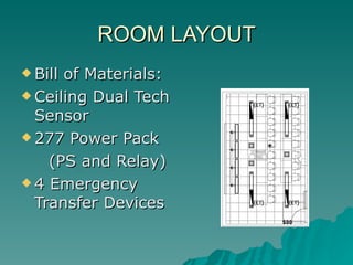
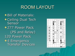
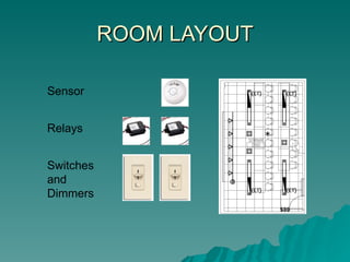
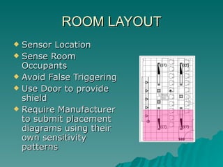
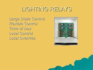
Advanced Lighting Controls
            Design
        Sunday May 28, 2006 2:00- 5:00

       Joseph M. (Jody) Good, III, LC, IESNA,
2006              IALD, LEED - AP
                              TM


            Spectrum Engineers, Inc.
                Salt Lake City, UT
Why Control Lighting?


1.User “program” requirements
2.Legal “Code” requirements
Why Control Lighting?


Facility owner may require or desire
   lighting controls for room
   functionality or energy rebates
Why Control Lighting?


Obvious Examples:
       Switch or dimmed lighting in Meeting
    Rooms, Classrooms,
Dimmed lighting in AV, training, and
    presentation rooms
Dimmed lighting in Video Teleconference
    rooms and Auditoriums
Why Control Lighting?


Energy Codes-
Control Requirements, Interior
ASHRAE/IESNA 90.1 2004
IECC
Mandatory Control
              Requirements:
      AUTOMATIC LIGHTING SHUTOFF
       All buildings > 5000 sq ft shall have an
           Automatic Control Device to shut off
                  building lighting in all spaces.
a. Time of day
b. Occupancy sensor
c. Signal from another system’s sensor
Mandatory Control
             Requirements:
SPACE CONTROL
All spaces with ceiling height partitions shall
     have at least one control device to
     independently control the general lighting
     in the space.
(IECC- Uniform Lighting Reduction Controls
     Required, with exceptions.)
Mandatory Control
          Requirements:

Manual control shall be able to
See the lighting ( or with pilot
  light) or remote for safety then
  clearly labeled
Mandatory Control
            Requirements:
Automatic control (30 minutes) after all
   occupants leave the space except
   spaces with “Multi-scene
   Controllers” in
Classrooms (some exceptions)
Conference & Meeting rooms
Employee Lunch and Break rooms
Mandatory Control
               Requirements:
All other spaces:
Each control device shall be manually or automatically
      by sensing the occupants.

For spaces up to 10,000 sq ft- 1 per 2500 sq ft max,
     over 10,000 sq ft, 1 per 10,000 sq ft max.

Capable of overriding time of day scheduled shutoff for
    no more than 4 hours. (IECC 2 Hours)
Mandatory Control
           Requirements:

Summary:
Time of day shutoff required in all
   spaces > 5,000 sq ft.
Large spaces require sub-divisions to
   automatically control or override.
Mandatory Control
             Requirements:
BIG EXCEPTION
Multi-scene Controllers” in
Classrooms (some exceptions)
Conference & Meeting rooms
Employee Lunch and Break rooms
Multi Scene controllers are NOT REQUIRED
     to be to be connected to other automatic
     lighting shutoff controls.
Controls for Exterior
                Lighting:


All non-exempt outdoor lighting
    must be controlled.
Astronomic clock or photocell.
Additional controls:


Display/ Accent/ Case/ Permanent
   Task lights, others.
Master Switch for Hotel Guestrooms
GREEN OWNER:


LEED tm: Minimum Energy Code: Controls
                       (Energy & Atmosphere Prerequisite 2)
       Enhanced Personal Lighting Controls
                     (Indoor Environmental Quality Credit 6.1)
       Reduced Energy : (Energy & Atmosphere Credit 1)
       Basic Commissioning:
                        (Energy & Atmosphere Prerequisite 1)
       Additional Commissioning:
                        (Energy & Atmosphere Prerequisite 3)
GETTING IT
 Doesit HAVE TO be controlled?
 CONTROL TYPE
  – Switched
  – Dimmed
 CONTROL       METHOD
  – Manual
  – Automatic
     Time,   Occupancy, Photocel, etc.
 LARGE   or   SMALL   SCALE
Passive Lighting Controls
   How to control lighting?
   PASSIVE - Local Autonomous Systems
   Occupancy Sensors
   Auto on and auto off
    OR Manual on auto off
   Self Adjusting Delays and Sensitivity
   Single or Dual Tech (PIR, Ultrasonic
    acoustic)
   Photo receptive feature
Passive Lighting Controls
 Relay   Systems
  – Time of Day Control
  – Dusk Dawn Shift Feature
  – Photo receptive feature
  – Local Override
     Key or Pushbutton Stations
     “Sentinel Switch”

  – Distributed Loadcenters Network
    Topology
ACTIVE Lighting Control
 Occupant   Intervention
 Switch

 Manual  Dimmer
 Manual on / Auto off Occupancy
  Sensor
 Preset Selection for Dimmers

  – Might be BMS or Time of Day / Photocel
    Controlled
Hybrid or Combination Systems
 Photocel on/ clock off
 Complex Occupancy sensor situations

    –   Multi Head
    –   Multi Relay
    –   (Emergency loads)
   Dual Technology Sensors
    – Any tech on / hold / off
    – Better: Both Tech on (or manual on) / any
      tech hold on / both tech off
Occupancy Sensors and
       Daylight Controls
 Occupants   prefer a occupancy sensor
  with photocel be set to use photocel
  to decide lights on when daylight
  present as lights are turned on when
  room becomes occupied
 Avoid turning lights off on occupants
Example Specifications
   Shall use microprocessor for motion
    signal analysis and internal, adaptive
    self-adjustment.
   No manual adjustment shall be required
    at the time of installation or during
    operation.
   Shall save learned and adjusted settings
    in non-volatile memory that retains all
    settings during power outages.
Example Specifications
   Shall recognize motion detected within
    20 seconds of turning off lighting as a
    false off. In response to a false off, the
    microprocessor shall increase the time-
    off setting.
   Maximum adapted time-out shall not
    exceed 30 minutes.
   Walk through feature shall shut off lights
    within 2.5 minutes after momentary
    occupancy.
Example Specifications
Shall beep before load is automatically
   switched off.
Shall have a 3-position service switch:
   off, auto, and on.
Four, selectable manual timer settings
   shall be available from 30sec to
   20min.
Available for wall or ceiling sensors
ROOM LAYOUT
 Billof Materials:
 Ceiling Dual Tech
  Sensor
 277 Power Pack

    (PS and Relay)
 4 Emergency
  Transfer Devices
ROOM LAYOUT
 Billof Materials:
 Ceiling Dual Tech
  Sensor
 277 Power Pack

    (PS and Relay)
120 Power Pack
 4 Emergency
  Transfer Devices
ROOM LAYOUT

Sensor


Relays


Switches
and
Dimmers
ROOM LAYOUT
 Sensor Location
 Sense Room
  Occupants
 Avoid False Triggering
 Use Door to provide
  shield
 Require Manufacturer
  to submit placement
  diagrams using their
  own sensitivity
  patterns
LIGHTING RELAYS
 Large Scale Control
 Flexible Control
 Time of Day
 Local Control
 Local Override
LIGHTING RELAYS
 Large Scale Control
 Flexible Control
 Time of Day
 Local Control
 Local Override
 Network Multiple
  Panels Together
LIGHTING RELAYS
 Small Scale Control
 Flexible Control
 Time of Day
 Local Control
 Local Override
 Network Multiple
  Panels Together
LIGHTING RELAYS
   Digital or Analog
    Switches or Stations
LIGHTING RELAYS
   Building Wide
    Solutions to Switching
    Problems
Building Management Systems
Often we have to interface with
 BMS Building Management
 Systems.

Here is a primer of the terms and
 technology used in this business.
Building Management Systems
   BMS “Language”
    • Points:
    • AI Analog Input
    • AO Analog Output
    • BI or DI Binary / Digital Input
    • BO or DO Binary / Digital Output
Building Management Systems
 Analog Input can be variable
  voltage, current, or resistance
  signal.
 Analog Output can be variable

  voltage or current.
Building Management Systems
 Binary or Digital I or O think
  “dry contact”.
 Dimming ballast on a BMS

  required 2 points for output:
    • 1 BI for switching the power on /
      off
    • 1 AO to provide the 1-10 volts.
Building Management Systems
 These are generated by a circuit
  on the serial signal “node” or
  “gateway”.
 Manufacturer specific hardware

  and software in a control system,
  to access BMS addressing and
  address to control properties of
  each node.
Building Management Systems
     BacNet on Ethernet
     or Ethernet


 Router/Gateway           BacNet      BacNet
                           Node        Node
      DDC Controller


      DDC Controller
                                   Monitored
                                   and
      DDC Controller               Controlled
                                   Load Devices

      BacNet or
      LonWorks
Building Management Systems

    Router/Gateway


   DDC Controller


   DDC Controller
                     Monitored
                     and
   DDC Controller    Controlled
                     Load Devices

    LonWorks
Building Management Systems
       BacNet on Ethernet
       or Ethernet


   Router/Gateway             BacNet     BacNet
                               Node       Node
            DDC Controller


                             Interface


BacNet or
LonWorks
Building Management Systems
Networks:
LonWorks – Proprietary, incremental license fee per device, RS485
          2 conductor, half duplex. Mostly more expensive, but
          can be competitive.

BacNet- Open standard, sponsored by ASHRAE., RS485 or Ethernet.
         Speed is < 10 system cycles per second.


There are others, ( ie: N2, CBus, Modbus,) but these 2 are the
majority of the systems,
Dimming For Function

                       Control
                       Zones:
                       1- Whiteboard
                       2- Downlights
                       3- Pendants
                       4-Side Wall
                          Slot
                       5- Rear Wall
                          Wash
DM-C OPTION #1

Various Loads, Including Power Amplifiers, if Required
DMC-1 DMC-2             DMC-4    DMC-5          DMC-3


           Line voltage in, 120 or 277 volts
DM-C OPTION #1
              With Emergency Bypass
Various Loads, Including Power Amplifiers, if Required
DMC-1     DMC-2        DMC-4     DMC-5           DMC-3/EM


           Line voltage in, 120 or 277 volts
“Preset Station”
                      DM-C OPTION #2
                      Networked Wall Box Dimmers


                   Line voltage in, 120 or 277 volts

         Preset Data
“Preset Station”
                   DM-C OPTION #3
                        “Wall Box System”


         Preset Data   Line voltage in 120
CLASSROOM
            Control
            Zones:
            1- Whiteboard
            2- Downlights
            3- Pendants
            4-Side Wall
               Slot
            5- Rear Wall
               Wash
Possible Interface
             Requirements
 Bac NET / Lon Works / BMS
 Audio/Video Controls, (AMX Crestron)

    • Direct Access- i.e. Lutron,
   Interface- Input, output, status
    feedback, Bi-directional, Serial Data:
    • RS 232- EIA/TIA Standard, 50 ft.
      limitation
    • RS 485- EIA/ TIA IEEE Standard, 4,000 ft,
      limitation, 2 or 4 wire, 32 taps
   Dry Contacts
Dimmer and Load Types
   Characteristics of Load determines
    technical capability of dimmer
   Incandescent: Resistive, simple loads.
    Construction can enhance noise
    transmission or suppression. Tungsten
    Halogen types of Incandescent are
    generally less noisy. They require a period
    of high temperature operation to maintain
    the tungsten cycle.
Dimmer and Load Types
   Magnetic Low Voltage- Generally sees load
    connected to transformer, almost complete
    dimming range. DC a danger.
   Neon Very similar to Magnetic LV, often
    with low end cutoff
   Electronic LV- Very Different, often called
    “Capacitive load”. Needs firm zero crossing
    (Start of dimming cycle) for power
    converter synchronization.
Dimmer and Load Types
Fluorescent -electronic dimming ballasts, 2
  or 3 wire control “line voltage phase
  control”. Or 4 wire 2 wires for switched
  power and 2 for 0-10 volt control signal.
 Emergency in General Must turn on load
  despite dimmer setting. Easy with
  incandescent & LV loads. Much harder
  with fluorescent loads. Prefer 2 wire
  control schemes for this purpose.
Fluorescent Dimmers
   3 Control Techniques
                         2 wire Phase Control and Neutral to 1 or more
                                  Dimming Ballast
                                  Tuwire & Mark 10 Known Brands

                         3 wire Phase Control Switched Power and Neutral
                                 to 1 or more Dimming Ballast

                         4 wire Switched power and Neutral with
                                  additional 2 low voltage 0-10 volt wired to
                                  1 or More Dimming Ballasts
                                  Helios, Mark 7, Known Brands

    NOT INTERCHANGABLE WITH SPECIFIC APPLICATIONS
Dimmer Technology
    (Forward) Phase Control, Triac, Dual SCRs
 “Reverse Phase Control” Dimmers
  Semiconductor must be able to turn off.
FET, IGBT semiconductors
 Sine-wave Dimmers Semiconductors to

  turn on and turn off circuit and to shape
  the dimmer output to track the shape of
  the wave of the incoming power.
High Density Dimming Systems
Rack Consideration
 Fault Current Rating
 Size and Mounting
 Cooling
    – Fans with Noise
    – Convection – may require cooler ambient
      temp
Dimmer Specifications - Racks
 DMX Isolation:
 All DMX512 & RS485 communication ports and remote contact input
  connections shall be optically isolated from all processor electronics
  by a minimum of 2,500V RMS isolation.

 Life Safety Code Panic: (Also bridge to Building Fire Alarm
  System)
 The Rack Processor Housing shall have the provision to select any
  of a maximum of 192 dimmer outputs to be activated by the PANIC
  function. The PANIC function shall be activated or de-activated by
  one or more local or remote contact closures.

 Dimmer and Processor Speed:
 The dimmer control electronics shall have 16 bit (minimum) fade
  processing and a dimmer update rate better than 16 ms
Dimmer Specifications - Racks
 Line Regulation:
The dimmer output levels shall be regulated for
  incoming line voltage variations. The regulation
  shall adjust for both RMS voltage and frequency
  changes of the incoming AC wave form.
  Regulation shall maintain the desired output
  voltage +/- .5V volt for the entire operation
  range (90 – 264 VAC). The regulation shall
  compensate for variations of the AC waveform
  on a dimmer-by-dimmer basis.
Dimmer Specifications - Racks
 Output Filtering:
Basic Rise dimmers shall have a rise time of not
  less than 350 microseconds A measured at 90
  degrees conduction angle B from 10% to 90%
  of output wave form C with dimmer operating at
  maximum load D. Voltage rate of rise (slew rate)
  must not exceed 420 millivolts per microsecond
  in any point of the wave under full load
  conditions
Dimmer Specifications - Racks
 Output Filtering:
 2.5.3 Medium rise time dimmers shall
  have a rise time of not less than 500
  microseconds
 2.5.4 Hi-Rise dimmers shall have a rise
  time of not less than 800 microseconds
Filtering Criteria
   A: Rise time- in microseconds, 350 minimum 800
    premium
   B: Conduction Angle- 90 degree worst case
   C: Percentage of waveform 10%-90%
    conventional, 10%-95% or others is improving
    spec by increasing amount if waveform
    measured.
   D: Load: Theatrical manufacturers measure at
    full load, (rarely achieved), other amounts as
    stated.
   E.: Slew Rate, some filters can take adequate
    overall time, but take too long to respond, for
    example, and result in noisy lamps.
Dimmer Specifications - Racks
 SINEWAVE Dimmers:
Dimmer output waveform shall be a fully
  symmetrical Sinewave at any output
  voltage setting eliminating all lamp noise
  and reducing reflected harmonics on the
  building power supply. Total Harmonic
  distortion shall be less than 1% and
  efficiency shall be 98%.
Dimmer Specifications - WBD
   SPEC From website information
    – DIMMERS
        Manufacturer:
        Electrical Specifications
           – Input: 120 VAC @ 60Hz, 277VAC @ 60Hz OK
           – Line Voltage Regulation
           Where is specification???? These can have line regulation, but
             what is it?
           – RFI Noise Suppression
           Sure, but what??? WBD have been measured (by me) at 110 ms,
             10-90% 90 degrees, full load. So “De-buzzing” coils (additional
             chokes) are sold for sensitive situations and loads.
        Maximum Load: 120V incandescent: 1500W stand-alone, OK
Rack Controls
Variety of Standalone and Centralized Controls
Bag of Tricks
• Favorite Devices to Know About
  – 277 volt LV Wall Box Dimmer
  – Line voltage Power Booster
  – 4 wire Fluorescent Dimming Ballast Interface
  – Emergency Transfer Device
  – Emergency Bypass Device
  – Dual Technology Sensors
  – Fluorescent Ballast Interfaces
Bag of Tricks
• Resettable Switch
• Dual Voltage Anything
Remember
• Today, Lighting Control is Mandatory in
  many cases
• Conceive the system by determining loads
  separately from control function
• Groups always work together, increase
  load, simplify programming
• Load types, ie Low voltage can affect your
  thinking
Thanks
• Lutron, Lightolier Controls, Leviton
  Controls, Strand Lighting, Bodine
• Sentry Switch
• Wattstopper, Sensor Switch,
• Whoever else I Forgot
• For Samples, Photos, and Website
  Illustrations.
Questions?

• Download at
www.spectrum–engineers.com/lighting

Go Visit these manufacturers and others on the
 Show Floor.
Please remember to complete the
         surveys / course evaluations.

                Thank you!
2006
             We hope you enjoy
             the trade show and
                 conference!

Dmx512 lightng contrl design

  • 1.
    Advanced Lighting Controls Design Sunday May 28, 2006 2:00- 5:00 Joseph M. (Jody) Good, III, LC, IESNA, 2006 IALD, LEED - AP TM Spectrum Engineers, Inc. Salt Lake City, UT
  • 2.
    Why Control Lighting? 1.User“program” requirements 2.Legal “Code” requirements
  • 3.
    Why Control Lighting? Facilityowner may require or desire lighting controls for room functionality or energy rebates
  • 4.
    Why Control Lighting? ObviousExamples: Switch or dimmed lighting in Meeting Rooms, Classrooms, Dimmed lighting in AV, training, and presentation rooms Dimmed lighting in Video Teleconference rooms and Auditoriums
  • 5.
    Why Control Lighting? EnergyCodes- Control Requirements, Interior ASHRAE/IESNA 90.1 2004 IECC
  • 6.
    Mandatory Control Requirements: AUTOMATIC LIGHTING SHUTOFF All buildings > 5000 sq ft shall have an Automatic Control Device to shut off building lighting in all spaces. a. Time of day b. Occupancy sensor c. Signal from another system’s sensor
  • 7.
    Mandatory Control Requirements: SPACE CONTROL All spaces with ceiling height partitions shall have at least one control device to independently control the general lighting in the space. (IECC- Uniform Lighting Reduction Controls Required, with exceptions.)
  • 8.
    Mandatory Control Requirements: Manual control shall be able to See the lighting ( or with pilot light) or remote for safety then clearly labeled
  • 9.
    Mandatory Control Requirements: Automatic control (30 minutes) after all occupants leave the space except spaces with “Multi-scene Controllers” in Classrooms (some exceptions) Conference & Meeting rooms Employee Lunch and Break rooms
  • 10.
    Mandatory Control Requirements: All other spaces: Each control device shall be manually or automatically by sensing the occupants. For spaces up to 10,000 sq ft- 1 per 2500 sq ft max, over 10,000 sq ft, 1 per 10,000 sq ft max. Capable of overriding time of day scheduled shutoff for no more than 4 hours. (IECC 2 Hours)
  • 11.
    Mandatory Control Requirements: Summary: Time of day shutoff required in all spaces > 5,000 sq ft. Large spaces require sub-divisions to automatically control or override.
  • 12.
    Mandatory Control Requirements: BIG EXCEPTION Multi-scene Controllers” in Classrooms (some exceptions) Conference & Meeting rooms Employee Lunch and Break rooms Multi Scene controllers are NOT REQUIRED to be to be connected to other automatic lighting shutoff controls.
  • 13.
    Controls for Exterior Lighting: All non-exempt outdoor lighting must be controlled. Astronomic clock or photocell.
  • 14.
    Additional controls: Display/ Accent/Case/ Permanent Task lights, others. Master Switch for Hotel Guestrooms
  • 15.
    GREEN OWNER: LEED tm:Minimum Energy Code: Controls (Energy & Atmosphere Prerequisite 2) Enhanced Personal Lighting Controls (Indoor Environmental Quality Credit 6.1) Reduced Energy : (Energy & Atmosphere Credit 1) Basic Commissioning: (Energy & Atmosphere Prerequisite 1) Additional Commissioning: (Energy & Atmosphere Prerequisite 3)
  • 16.
    GETTING IT  DoesitHAVE TO be controlled?  CONTROL TYPE – Switched – Dimmed  CONTROL METHOD – Manual – Automatic  Time, Occupancy, Photocel, etc.  LARGE or SMALL SCALE
  • 17.
    Passive Lighting Controls  How to control lighting?  PASSIVE - Local Autonomous Systems  Occupancy Sensors  Auto on and auto off  OR Manual on auto off  Self Adjusting Delays and Sensitivity  Single or Dual Tech (PIR, Ultrasonic acoustic)  Photo receptive feature
  • 18.
    Passive Lighting Controls Relay Systems – Time of Day Control – Dusk Dawn Shift Feature – Photo receptive feature – Local Override  Key or Pushbutton Stations  “Sentinel Switch” – Distributed Loadcenters Network Topology
  • 19.
    ACTIVE Lighting Control Occupant Intervention  Switch  Manual Dimmer  Manual on / Auto off Occupancy Sensor  Preset Selection for Dimmers – Might be BMS or Time of Day / Photocel Controlled
  • 20.
    Hybrid or CombinationSystems  Photocel on/ clock off  Complex Occupancy sensor situations – Multi Head – Multi Relay – (Emergency loads)  Dual Technology Sensors – Any tech on / hold / off – Better: Both Tech on (or manual on) / any tech hold on / both tech off
  • 21.
    Occupancy Sensors and Daylight Controls  Occupants prefer a occupancy sensor with photocel be set to use photocel to decide lights on when daylight present as lights are turned on when room becomes occupied  Avoid turning lights off on occupants
  • 22.
    Example Specifications  Shall use microprocessor for motion signal analysis and internal, adaptive self-adjustment.  No manual adjustment shall be required at the time of installation or during operation.  Shall save learned and adjusted settings in non-volatile memory that retains all settings during power outages.
  • 23.
    Example Specifications  Shall recognize motion detected within 20 seconds of turning off lighting as a false off. In response to a false off, the microprocessor shall increase the time- off setting.  Maximum adapted time-out shall not exceed 30 minutes.  Walk through feature shall shut off lights within 2.5 minutes after momentary occupancy.
  • 24.
    Example Specifications Shall beepbefore load is automatically switched off. Shall have a 3-position service switch: off, auto, and on. Four, selectable manual timer settings shall be available from 30sec to 20min. Available for wall or ceiling sensors
  • 25.
    ROOM LAYOUT  BillofMaterials:  Ceiling Dual Tech Sensor  277 Power Pack (PS and Relay)  4 Emergency Transfer Devices
  • 26.
    ROOM LAYOUT  BillofMaterials:  Ceiling Dual Tech Sensor  277 Power Pack (PS and Relay) 120 Power Pack  4 Emergency Transfer Devices
  • 27.
  • 28.
    ROOM LAYOUT  SensorLocation  Sense Room Occupants  Avoid False Triggering  Use Door to provide shield  Require Manufacturer to submit placement diagrams using their own sensitivity patterns
  • 29.
    LIGHTING RELAYS  LargeScale Control  Flexible Control  Time of Day  Local Control  Local Override
  • 30.
    LIGHTING RELAYS  LargeScale Control  Flexible Control  Time of Day  Local Control  Local Override  Network Multiple Panels Together
  • 31.
    LIGHTING RELAYS  SmallScale Control  Flexible Control  Time of Day  Local Control  Local Override  Network Multiple Panels Together
  • 32.
    LIGHTING RELAYS  Digital or Analog Switches or Stations
  • 33.
    LIGHTING RELAYS  Building Wide Solutions to Switching Problems
  • 34.
    Building Management Systems Oftenwe have to interface with BMS Building Management Systems. Here is a primer of the terms and technology used in this business.
  • 35.
    Building Management Systems  BMS “Language” • Points: • AI Analog Input • AO Analog Output • BI or DI Binary / Digital Input • BO or DO Binary / Digital Output
  • 36.
    Building Management Systems Analog Input can be variable voltage, current, or resistance signal.  Analog Output can be variable voltage or current.
  • 37.
    Building Management Systems Binary or Digital I or O think “dry contact”.  Dimming ballast on a BMS required 2 points for output: • 1 BI for switching the power on / off • 1 AO to provide the 1-10 volts.
  • 38.
    Building Management Systems These are generated by a circuit on the serial signal “node” or “gateway”.  Manufacturer specific hardware and software in a control system, to access BMS addressing and address to control properties of each node.
  • 39.
    Building Management Systems BacNet on Ethernet or Ethernet Router/Gateway BacNet BacNet Node Node DDC Controller DDC Controller Monitored and DDC Controller Controlled Load Devices BacNet or LonWorks
  • 40.
    Building Management Systems Router/Gateway DDC Controller DDC Controller Monitored and DDC Controller Controlled Load Devices LonWorks
  • 41.
    Building Management Systems BacNet on Ethernet or Ethernet Router/Gateway BacNet BacNet Node Node DDC Controller Interface BacNet or LonWorks
  • 42.
    Building Management Systems Networks: LonWorks– Proprietary, incremental license fee per device, RS485 2 conductor, half duplex. Mostly more expensive, but can be competitive. BacNet- Open standard, sponsored by ASHRAE., RS485 or Ethernet. Speed is < 10 system cycles per second. There are others, ( ie: N2, CBus, Modbus,) but these 2 are the majority of the systems,
  • 43.
    Dimming For Function Control Zones: 1- Whiteboard 2- Downlights 3- Pendants 4-Side Wall Slot 5- Rear Wall Wash
  • 44.
    DM-C OPTION #1 VariousLoads, Including Power Amplifiers, if Required DMC-1 DMC-2 DMC-4 DMC-5 DMC-3 Line voltage in, 120 or 277 volts
  • 45.
    DM-C OPTION #1 With Emergency Bypass Various Loads, Including Power Amplifiers, if Required DMC-1 DMC-2 DMC-4 DMC-5 DMC-3/EM Line voltage in, 120 or 277 volts
  • 46.
    “Preset Station” DM-C OPTION #2 Networked Wall Box Dimmers Line voltage in, 120 or 277 volts Preset Data
  • 47.
    “Preset Station” DM-C OPTION #3 “Wall Box System” Preset Data Line voltage in 120
  • 48.
    CLASSROOM Control Zones: 1- Whiteboard 2- Downlights 3- Pendants 4-Side Wall Slot 5- Rear Wall Wash
  • 49.
    Possible Interface Requirements  Bac NET / Lon Works / BMS  Audio/Video Controls, (AMX Crestron) • Direct Access- i.e. Lutron,  Interface- Input, output, status feedback, Bi-directional, Serial Data: • RS 232- EIA/TIA Standard, 50 ft. limitation • RS 485- EIA/ TIA IEEE Standard, 4,000 ft, limitation, 2 or 4 wire, 32 taps  Dry Contacts
  • 50.
    Dimmer and LoadTypes  Characteristics of Load determines technical capability of dimmer  Incandescent: Resistive, simple loads. Construction can enhance noise transmission or suppression. Tungsten Halogen types of Incandescent are generally less noisy. They require a period of high temperature operation to maintain the tungsten cycle.
  • 51.
    Dimmer and LoadTypes  Magnetic Low Voltage- Generally sees load connected to transformer, almost complete dimming range. DC a danger.  Neon Very similar to Magnetic LV, often with low end cutoff  Electronic LV- Very Different, often called “Capacitive load”. Needs firm zero crossing (Start of dimming cycle) for power converter synchronization.
  • 52.
    Dimmer and LoadTypes Fluorescent -electronic dimming ballasts, 2 or 3 wire control “line voltage phase control”. Or 4 wire 2 wires for switched power and 2 for 0-10 volt control signal.  Emergency in General Must turn on load despite dimmer setting. Easy with incandescent & LV loads. Much harder with fluorescent loads. Prefer 2 wire control schemes for this purpose.
  • 53.
    Fluorescent Dimmers  3 Control Techniques 2 wire Phase Control and Neutral to 1 or more Dimming Ballast Tuwire & Mark 10 Known Brands 3 wire Phase Control Switched Power and Neutral to 1 or more Dimming Ballast 4 wire Switched power and Neutral with additional 2 low voltage 0-10 volt wired to 1 or More Dimming Ballasts Helios, Mark 7, Known Brands NOT INTERCHANGABLE WITH SPECIFIC APPLICATIONS
  • 54.
    Dimmer Technology (Forward) Phase Control, Triac, Dual SCRs  “Reverse Phase Control” Dimmers Semiconductor must be able to turn off. FET, IGBT semiconductors  Sine-wave Dimmers Semiconductors to turn on and turn off circuit and to shape the dimmer output to track the shape of the wave of the incoming power.
  • 55.
  • 56.
    Rack Consideration  FaultCurrent Rating  Size and Mounting  Cooling – Fans with Noise – Convection – may require cooler ambient temp
  • 57.
    Dimmer Specifications -Racks  DMX Isolation:  All DMX512 & RS485 communication ports and remote contact input connections shall be optically isolated from all processor electronics by a minimum of 2,500V RMS isolation.  Life Safety Code Panic: (Also bridge to Building Fire Alarm System)  The Rack Processor Housing shall have the provision to select any of a maximum of 192 dimmer outputs to be activated by the PANIC function. The PANIC function shall be activated or de-activated by one or more local or remote contact closures.  Dimmer and Processor Speed:  The dimmer control electronics shall have 16 bit (minimum) fade processing and a dimmer update rate better than 16 ms
  • 58.
    Dimmer Specifications -Racks  Line Regulation: The dimmer output levels shall be regulated for incoming line voltage variations. The regulation shall adjust for both RMS voltage and frequency changes of the incoming AC wave form. Regulation shall maintain the desired output voltage +/- .5V volt for the entire operation range (90 – 264 VAC). The regulation shall compensate for variations of the AC waveform on a dimmer-by-dimmer basis.
  • 59.
    Dimmer Specifications -Racks  Output Filtering: Basic Rise dimmers shall have a rise time of not less than 350 microseconds A measured at 90 degrees conduction angle B from 10% to 90% of output wave form C with dimmer operating at maximum load D. Voltage rate of rise (slew rate) must not exceed 420 millivolts per microsecond in any point of the wave under full load conditions
  • 60.
    Dimmer Specifications -Racks  Output Filtering:  2.5.3 Medium rise time dimmers shall have a rise time of not less than 500 microseconds  2.5.4 Hi-Rise dimmers shall have a rise time of not less than 800 microseconds
  • 61.
    Filtering Criteria  A: Rise time- in microseconds, 350 minimum 800 premium  B: Conduction Angle- 90 degree worst case  C: Percentage of waveform 10%-90% conventional, 10%-95% or others is improving spec by increasing amount if waveform measured.  D: Load: Theatrical manufacturers measure at full load, (rarely achieved), other amounts as stated.  E.: Slew Rate, some filters can take adequate overall time, but take too long to respond, for example, and result in noisy lamps.
  • 62.
    Dimmer Specifications -Racks  SINEWAVE Dimmers: Dimmer output waveform shall be a fully symmetrical Sinewave at any output voltage setting eliminating all lamp noise and reducing reflected harmonics on the building power supply. Total Harmonic distortion shall be less than 1% and efficiency shall be 98%.
  • 63.
    Dimmer Specifications -WBD  SPEC From website information – DIMMERS  Manufacturer:  Electrical Specifications – Input: 120 VAC @ 60Hz, 277VAC @ 60Hz OK – Line Voltage Regulation Where is specification???? These can have line regulation, but what is it? – RFI Noise Suppression Sure, but what??? WBD have been measured (by me) at 110 ms, 10-90% 90 degrees, full load. So “De-buzzing” coils (additional chokes) are sold for sensitive situations and loads.  Maximum Load: 120V incandescent: 1500W stand-alone, OK
  • 64.
    Rack Controls Variety ofStandalone and Centralized Controls
  • 65.
    Bag of Tricks •Favorite Devices to Know About – 277 volt LV Wall Box Dimmer – Line voltage Power Booster – 4 wire Fluorescent Dimming Ballast Interface – Emergency Transfer Device – Emergency Bypass Device – Dual Technology Sensors – Fluorescent Ballast Interfaces
  • 66.
    Bag of Tricks •Resettable Switch • Dual Voltage Anything
  • 67.
    Remember • Today, LightingControl is Mandatory in many cases • Conceive the system by determining loads separately from control function • Groups always work together, increase load, simplify programming • Load types, ie Low voltage can affect your thinking
  • 68.
    Thanks • Lutron, LightolierControls, Leviton Controls, Strand Lighting, Bodine • Sentry Switch • Wattstopper, Sensor Switch, • Whoever else I Forgot • For Samples, Photos, and Website Illustrations.
  • 69.
    Questions? • Download at www.spectrum–engineers.com/lighting GoVisit these manufacturers and others on the Show Floor.
  • 70.
    Please remember tocomplete the surveys / course evaluations. Thank you! 2006 We hope you enjoy the trade show and conference!