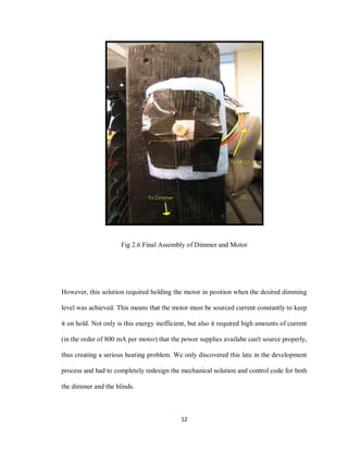
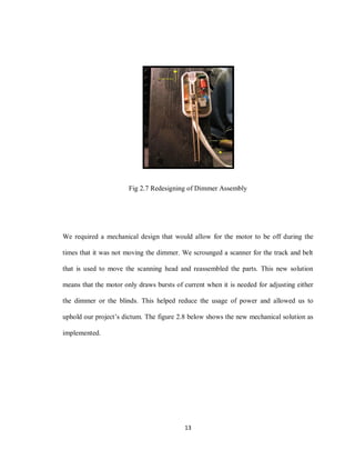
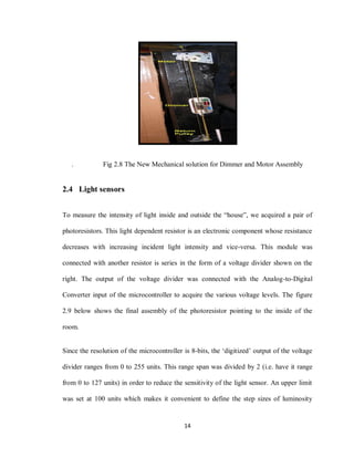
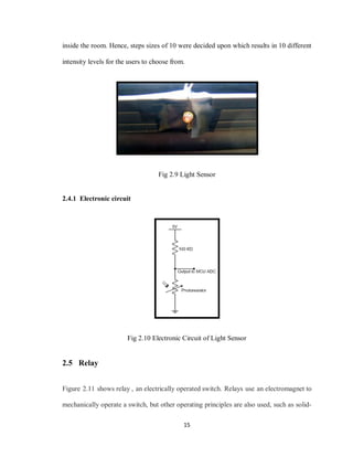
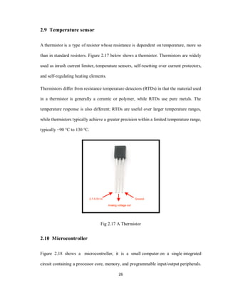
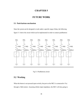
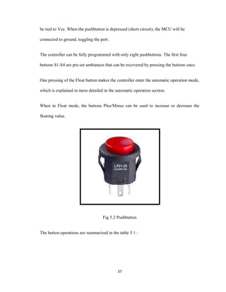
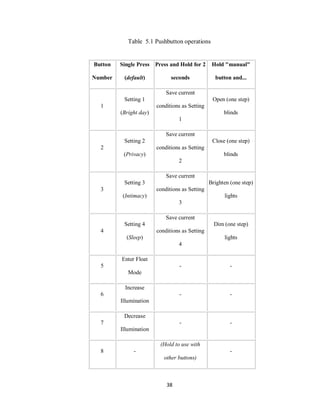
The document describes a self-configuring automatic light control system that senses light levels inside and outside a room and controls window blinds and lighting to maintain a set level of illumination. It uses occupancy detectors, light sensors, a blinds controller, dimmer, temperature sensor, push buttons, microcontroller and LCD display. The system aims to save energy by keeping unoccupied rooms unlit and maximizing natural light. It allows users to set different pre-programmed lighting ambiences. The project addresses California's energy code requirements for lighting and controls in homes.

![3
High efficacy lights - fluorescent, compact fluorescent (CFL) or high-intensity
discharge (HID) lamps.
Fluorescent, CFL, and HID lights must not have a medium screw base socket.
Lamps rated 13 watts or greater must have an electronic ballast.
Though we did not have time or money to work on the ballast, we think that all other
points were covered.
Furthermore, latest microcontroller was implemented for communicating between the
sensors and the human beings. Other than those, after a reasonable search for such items,
we really didn't find infringement of any existing patents, trademarks or copyrights.
1.3.1 Dimmers
Part of setting the right ambience in a room is controlling the intensity of the lights. Very
bright lights have a much different effect on people than low lights. It controls the
intensity of the light by dimming an incandescent light bulb. Dimming can be achieved in
different ways, the most straightforward being a variable resistance that varies the voltage
coming in to the lamp. However, variable resistance dimming is very inefficient in terms
of energy, as the resistance is turning energy into heat that is not used.[1]
1.3.2 Occupancy sensors
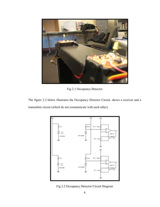
An occupancy detector circuit was built using a pair of infrared transceivers (Receiver:
LTR-4206E; Transmitter: LTE-4208). When an opaque object is put in between the
aligned transceiver current flows through the receiver. Putting one transceiver on a door](https://image.slidesharecdn.com/6c184f38-a3e0-4316-8a98-38a35b4b285d-170202073720/85/Final-Thesis-11-320.jpg)


![9
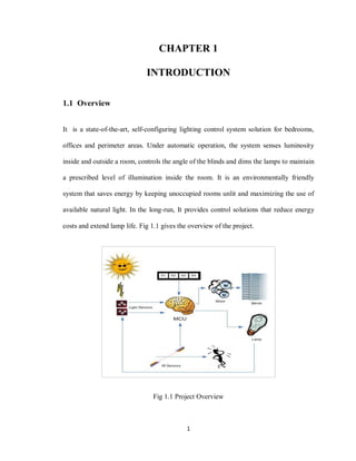
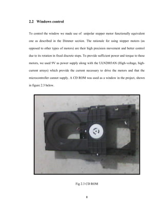
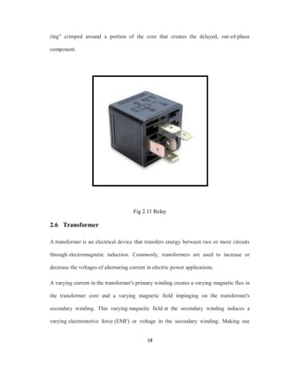
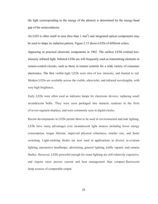
2.2.1 Stepper motor
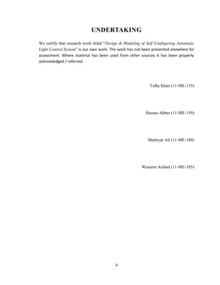
The stepper motor’s electrical input consists of six wires; four for control and two for
power supply. In order to drive the motor, a particular sequence of high/low voltages is
required to be applied to the four control wires. [2]
The documentation we found online claimed a two-hot assignment of codes which we
later found out was not the only way to control the motor. Using two-hot assignment
results in an increase of about 1.4 times in torque at the expense of twice the amount of
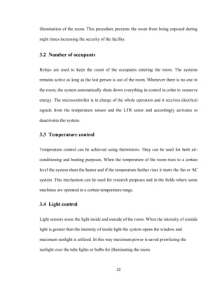
current. The motor can also be controlled by four one-hot assignment codes. The blinds
control required the torque that is created by using two-hot codes, while the dimmer only
needs the torque generated by the one-hot codes. The motor set-up for the blinds is shown
below in figure 2.4.
Fig 2.4 Stepper Motor](https://image.slidesharecdn.com/6c184f38-a3e0-4316-8a98-38a35b4b285d-170202073720/85/Final-Thesis-17-320.jpg)
![16
state relays. Relays are used where it is necessary to control a circuit by a low-power
signal (with complete electrical isolation between control and controlled circuits), or
where several circuits must be controlled by one signal. The first relays were used in long
distance telegraph circuits as amplifiers: they repeated the signal coming in from one
circuit and re-transmitted it on another circuit. Relays were used extensively in telephone
exchanges and early computers to perform logical operations.
2.5.1 Protective relays
A type of relay that can handle the high power required to directly control an electric
motor or other loads is called a contactor. Solid-state relays control power circuits with
no moving parts, instead using a semiconductor device to perform switching. Relays with
calibrated operating characteristics and sometimes multiple operating coils are used to
protect electrical circuits from overload or faults; in modern electric power systems these
functions are performed by digital instruments still called "protective relays". [3]
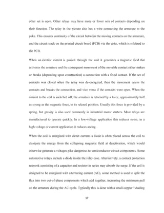
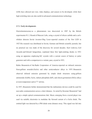
2.5.2 Working
A simple electromagnetic relay consists of a coil of wire wrapped around a soft iron core,
an iron yoke which provides a low reluctance path for magnetic flux, a movable
iron armature, and one or more sets of contacts. The armature is hinged to the yoke and
mechanically linked to one or more sets of moving contacts. It is held in place by
a spring so that when the relay is de-energized there is an air gap in the magnetic circuit.
In this condition, one of the two sets of contacts in the relay pictured is closed, and the](https://image.slidesharecdn.com/6c184f38-a3e0-4316-8a98-38a35b4b285d-170202073720/85/Final-Thesis-24-320.jpg)
![25
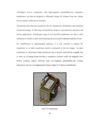
LCDs are used in a wide range of applications including computer monitors,
televisions, instrument panels, aircraft cockpit displays, and signage. They are common
in consumer devices such as DVD players, gaming devices, clocks, watches, calculators,
and telephones, and have replaced cathode ray tube (CRT) displays in most applications.
They are available in a wider range of screen sizes than CRT and plasma displays, and
since they do not use phosphors, they do not suffer image burn-in. LCDs are, however,
susceptible to image persistence. [4]
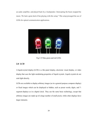
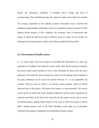
The LCD screen is more energy efficient and can be disposed of more safely than a CRT.
Its low electrical power consumption enables it to be used in battery-
powered electronic equipment. It is an electronically modulated optical device made up
of any number of segments filled with liquid crystals and arrayed in front of a light
source (backlight) or reflector to produce images in color or monochrome. Liquid crystals
were first discovered in 1888. Figure 2.16 shows an LCD.
Fig 2.16 Liquid crystal display (LCD)](https://image.slidesharecdn.com/6c184f38-a3e0-4316-8a98-38a35b4b285d-170202073720/85/Final-Thesis-33-320.jpg)
![27
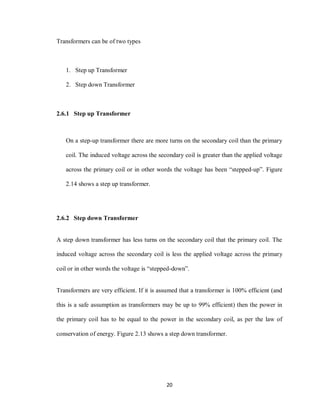
Program memory in the form of Ferroelectric RAM, NOR flash or OTP ROM is also
often included on chip, as well as a typically small amount of RAM.
Microcontrollers are used in automatically controlled products and devices, such as
automobile engine control systems, implantable medical devices, remote controls, office
machines, appliances, power tools, toys and other embedded systems. By reducing the
size and cost compared to a design that uses a separate microprocessor, memory, and
input/output devices, microcontrollers make it economical to digitally control even more
devices and processes. Mixed signal microcontrollers are common, integrating analog
components needed to control non-digital electronic systems.
Some microcontrollers may use four-bit words and operate at clock rate frequencies as
low as 4 kHz, for low power consumption. They will generally have the ability to retain
functionality while waiting for an event such as a button press or other interrupt; power
consumption while sleeping may be just nanowatts, making many of them well suited for
long lasting battery applications. Other microcontrollers may serve performance-critical
roles, where they may need to act more like a digital signal processor (DSP), with higher
clock speeds and power consumption. [5]
Fig 2.18 Microcontroller](https://image.slidesharecdn.com/6c184f38-a3e0-4316-8a98-38a35b4b285d-170202073720/85/Final-Thesis-35-320.jpg)

![40
References
[1] Bellman, Wilard F. (2001). LIGHTING THE STAGE: Art and Practice, Third
Edition, Chapter 4 –The Control Console, Broadway Press, Inc., Louisville
Kentucky, ISBN 0-911747-40-0
[2] Liptak, Bela G. (2005). Instrument Engineers' Handbook: Process Control and
Optimization. CRC Press. p. 2464. ISBN 978-0-8493-1081-2
[3] https://www.digikey.com/product-search/en/relays
[4] http://www.businesskorea.co.kr/article/8579/cut-and-run-taiwan-controlled-lcd-
panel-maker-danger-shutdown-without-further
[5] Heath, Steve (2003). Embedded systems design. EDN series for design engineers (2
ed.). Newnes. pp. 11–12. ISBN 9780750655460.](https://image.slidesharecdn.com/6c184f38-a3e0-4316-8a98-38a35b4b285d-170202073720/85/Final-Thesis-48-320.jpg)