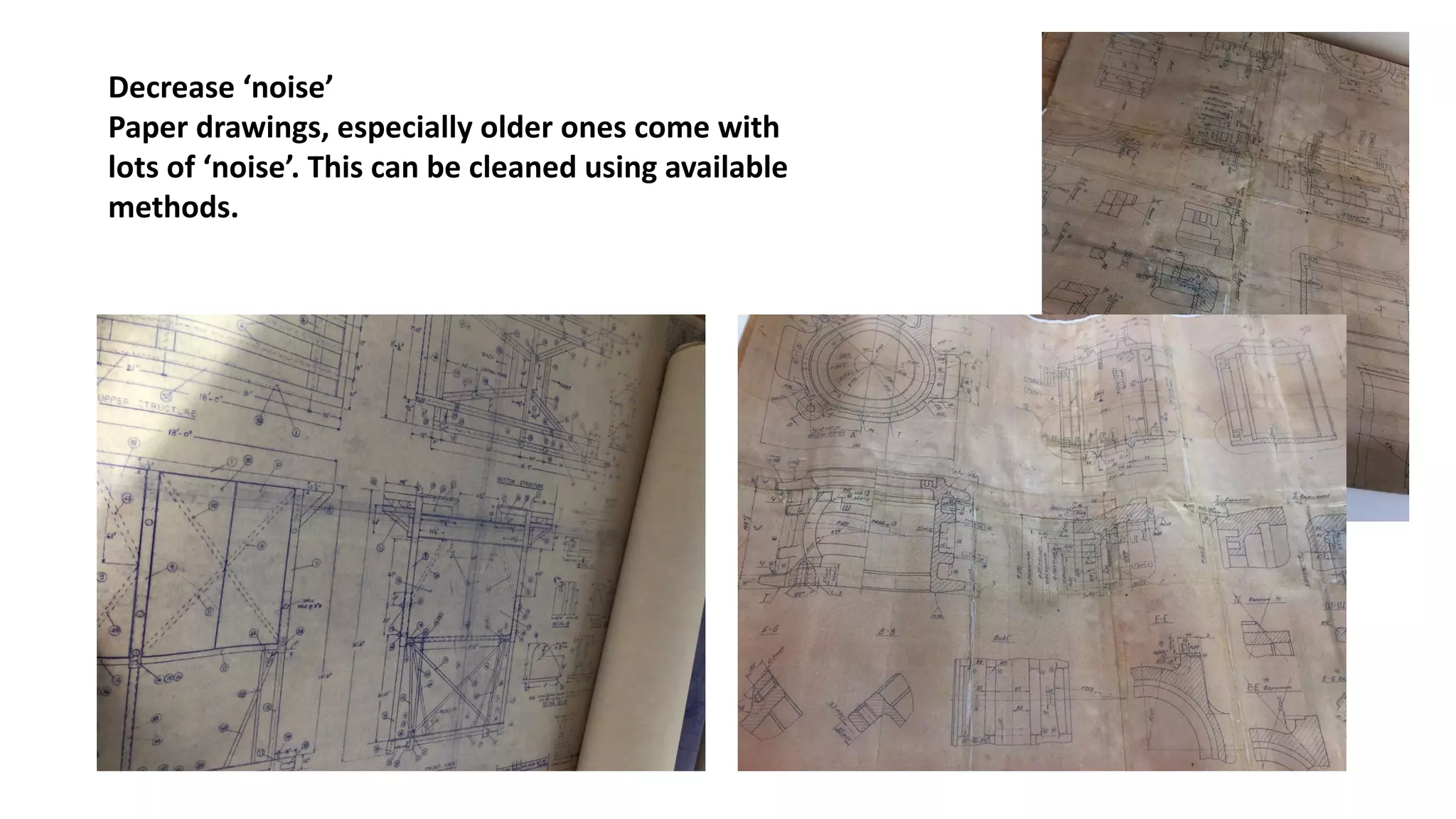
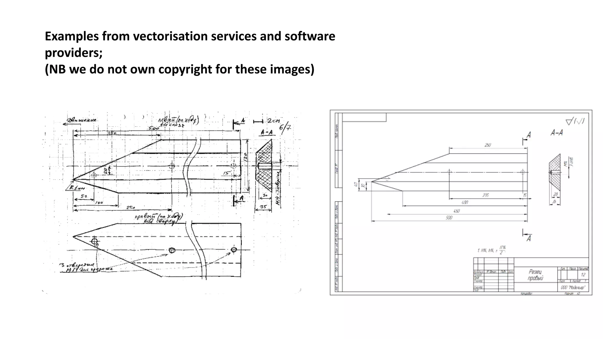
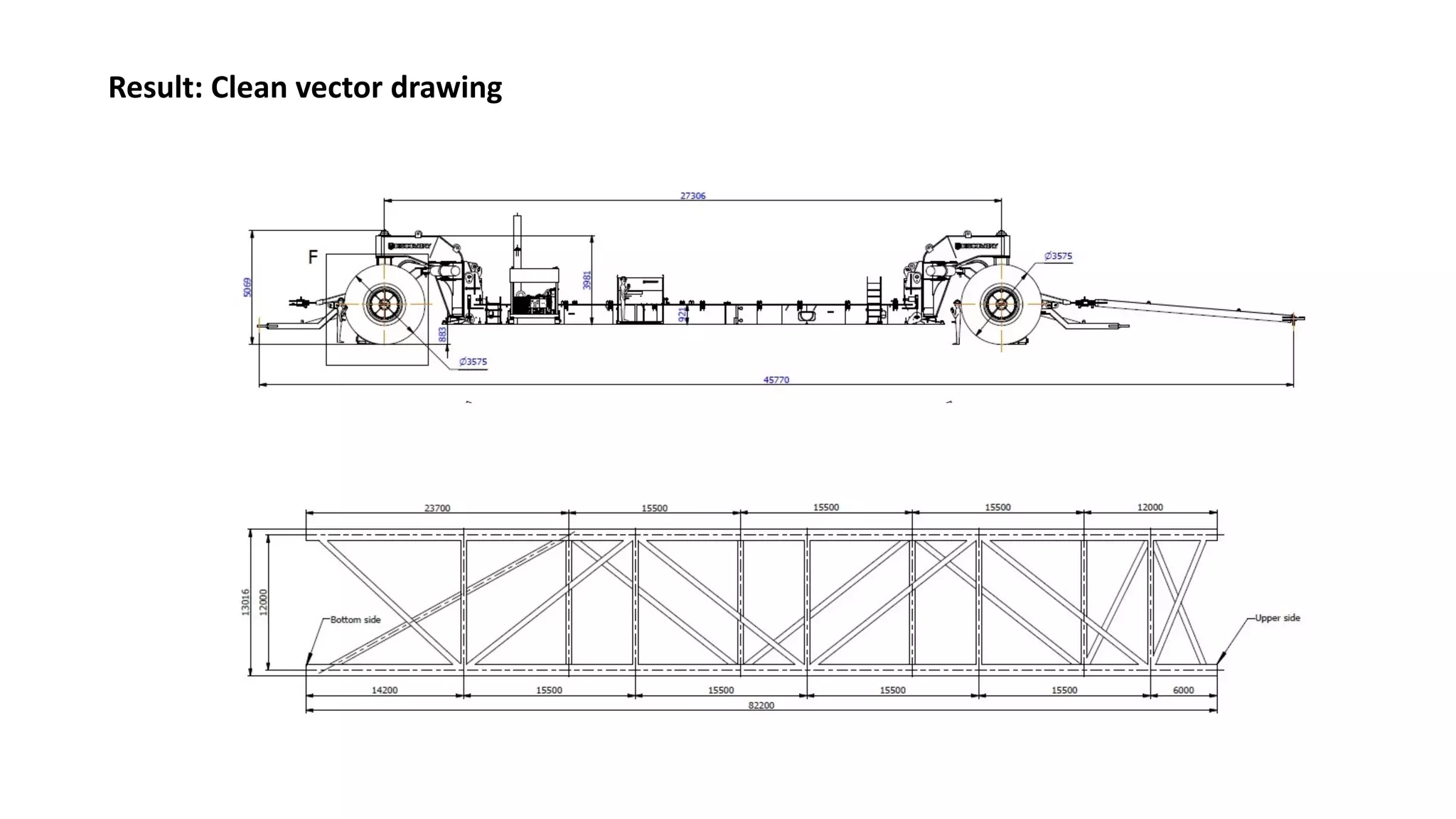
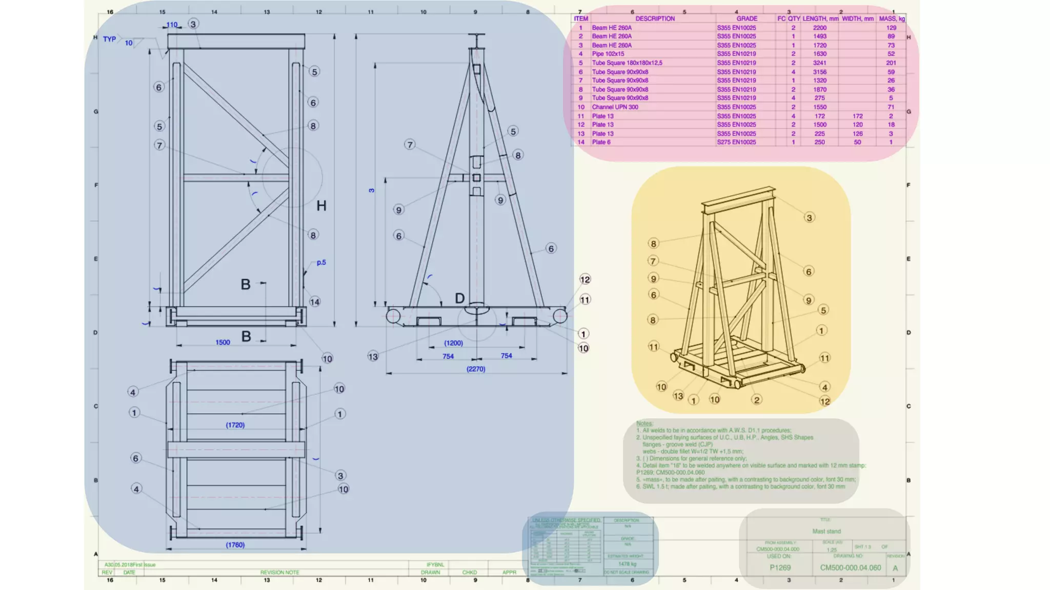
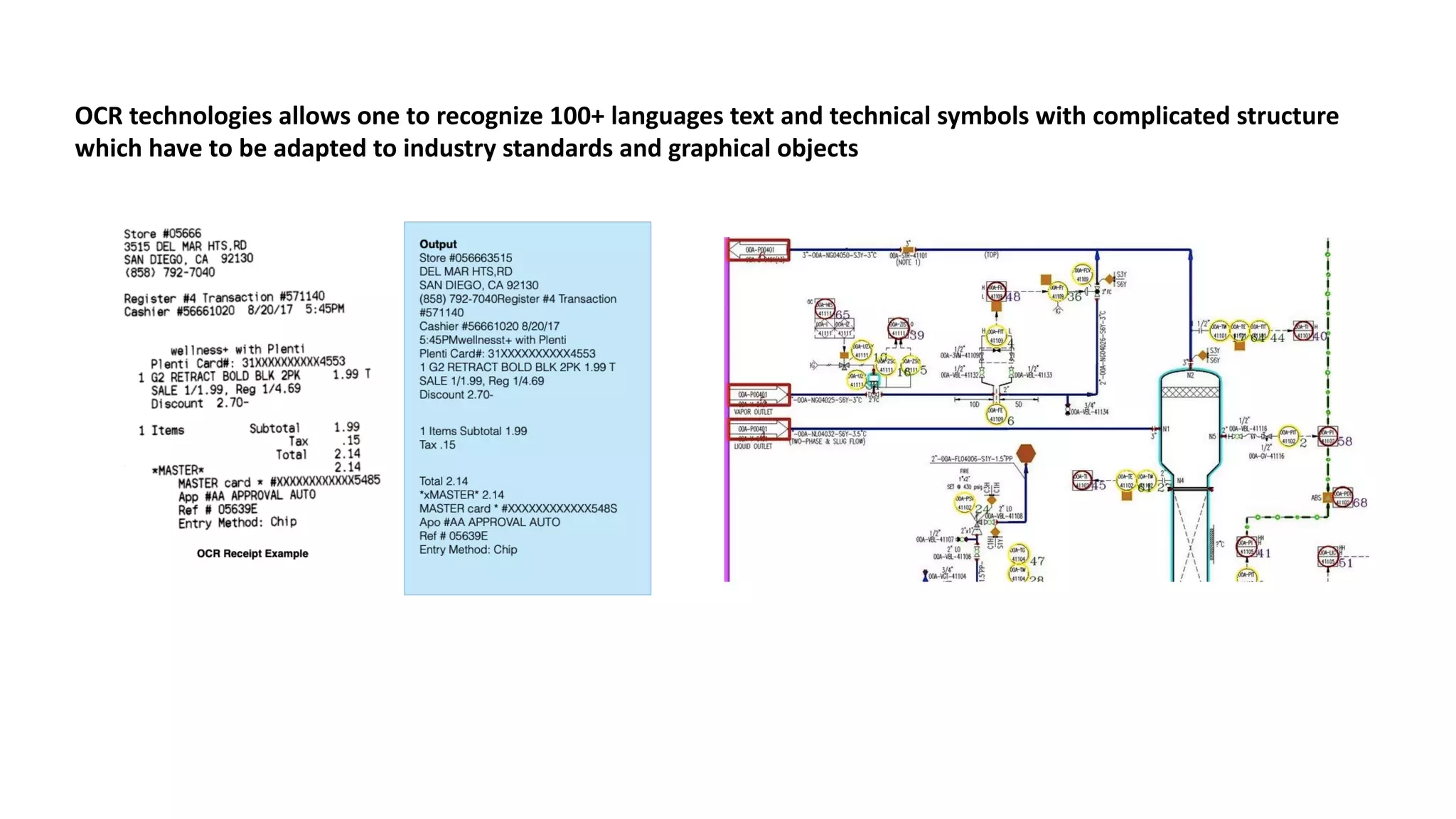
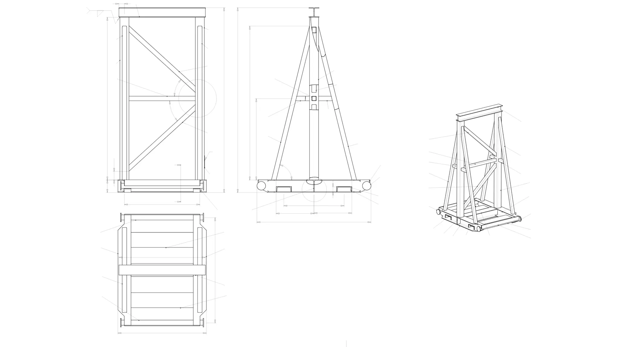
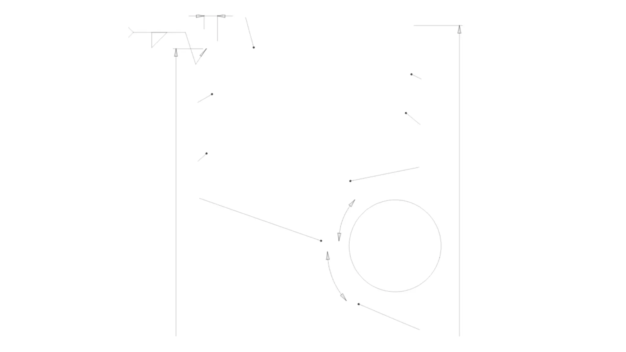
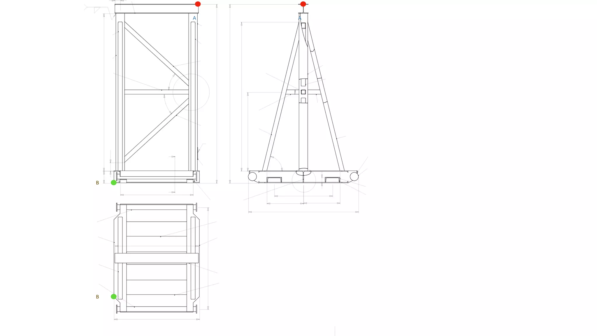
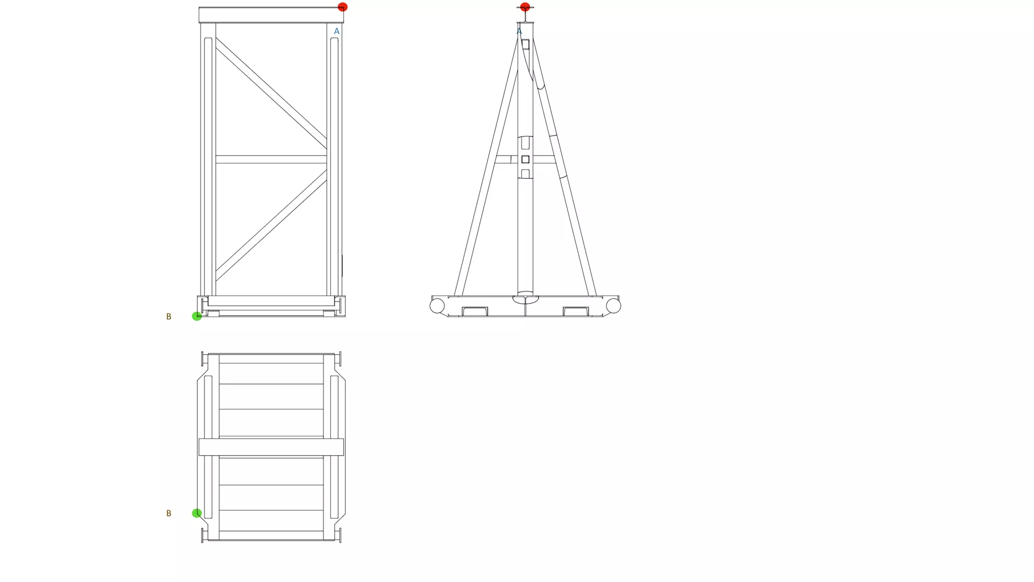
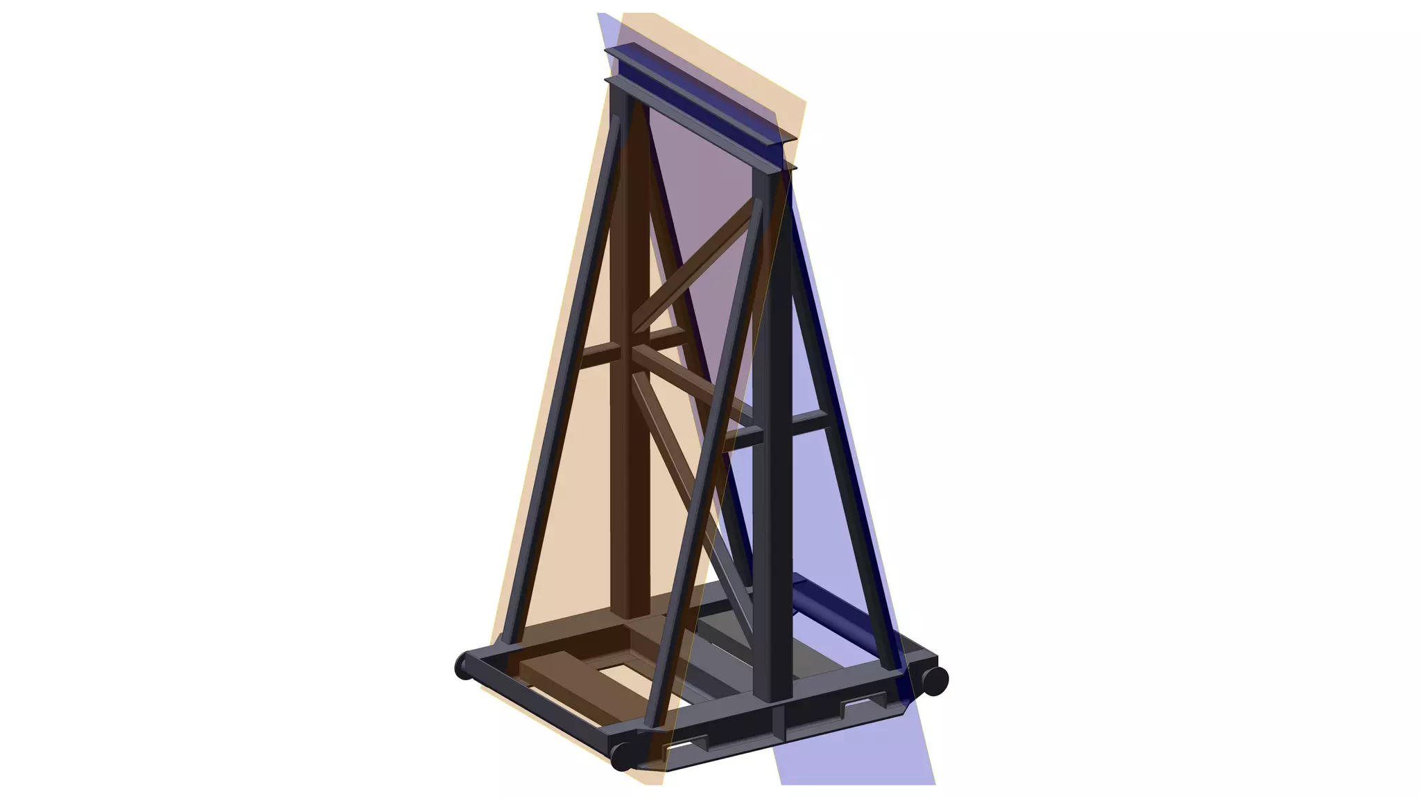
DII
Presentation 3
Reading drawings
and creating 3-D models out of 2-D drawings
The approach and key methods
1. To get the exact information on an object’s parts and assemblies, its volumetric
model and composition
2. To get exact information about materials and components of the object
3. To be able to obtain all information from the drawings and convert it into a 3-D
model in a compatible software package.
The drawing must be converted to the selected format. Thus, DII’s AI platform has to
read the information from the available drawings in a similar way to a human.
Tasks
0. Prepare the drawing for recognition. “De-noise” the drawing and “vectorise” the
image (converting from a raster to a vector image).
1. Define the drawing’s functional areas
2. Recognise signs and symbols
3. Distinguish service graphics from the object’s dimensions
4. Relate geometry with service signs and symbols
5. Turn 2-D views and the material library into a precise 3-D model
Steps
0. De-noise and vectorise
The	images	are	prepared	for	future	work.	In	most	
cases	we	can	use	available	algorithms	and	
integrate	them	into	our	software.
Decrease	‘noise’
Paper	drawings,	especially	older	ones	come	with	
lots	of	‘noise’.	This	can	be	cleaned	using	available	
methods.
Scanned	drawings	also	need	to	be	‘vectorised’
meaning	the	image	is	converted	into	vector	format.
Numerous	automatic	solutions	are	available.
(https://en.wikipedia.org/wiki/Image_tracing)
Examples	from	vectorisation	services	and	software	
providers;
(NB	we	do	not	own	copyright	for	these	images)
Examples	from	
vectorisation	
services	and	
software	
providers.
(NB	we	do	not	
own	copyright	for	
these	images).
Result:	Clean	vector	drawing
1. Define the drawing’s functional
areas
Using	computer	vision-(CV)	trained	software,	we	
will	be	able	to	determine	key	functional	areas	of	
the	drawings.	Existing	CV	object	and	area	
detection	algorithms	will	be	used.	Training	will	be	
required	for	the	engineering	drawings’	domain.
Image	detection	and	segmentation	are	both	mature	technologies and need	to	be	transferred	to	
CAD	objects	/	labels
Object	views
Bill	of	materials
Isometry
Notes
Title
2. Recognise symbols and special
signs
Existing	text	and	symbol	detection	algorithms	will	
be	used.	It	needs	knowledge	transfer	for	the	
engineering	drawings’	domain.
OCR	technologies	allows	one	to	recognize	100+	languages	text	and	technical	symbols	with	complicated	structure
which have	to	be	adapted	to	industry	standards	and	graphical	objects
3. Distinguish service graphics from
objects
Combining	computer	vision	and	one’s	own	library	
of	service	graphics
AA
B
B
AA
B
B
4. Relate geometry with service
signs and symbols
Combine	computer	vision	and	standard	rules	of	
automatic	reading.	R&D	is	still	required	with	
software	implementation	according	to	ISO	
standards.
Glass	cube	projection	–
Orthographic	projection	method	
used	for	a	2-D	to	3-D	transformation
5. Turn 2-D views and bill of
materials into a 3-D model
Combine	a	digital	view	projection	with	a	bill	of	
materials	(BOM)
Requires	BOM	digitisation	and	
object	assembly	algorithms
Thank you
This was Presentation-3 of 3 outlining
DII business case.
www.dii.ai

DII p3