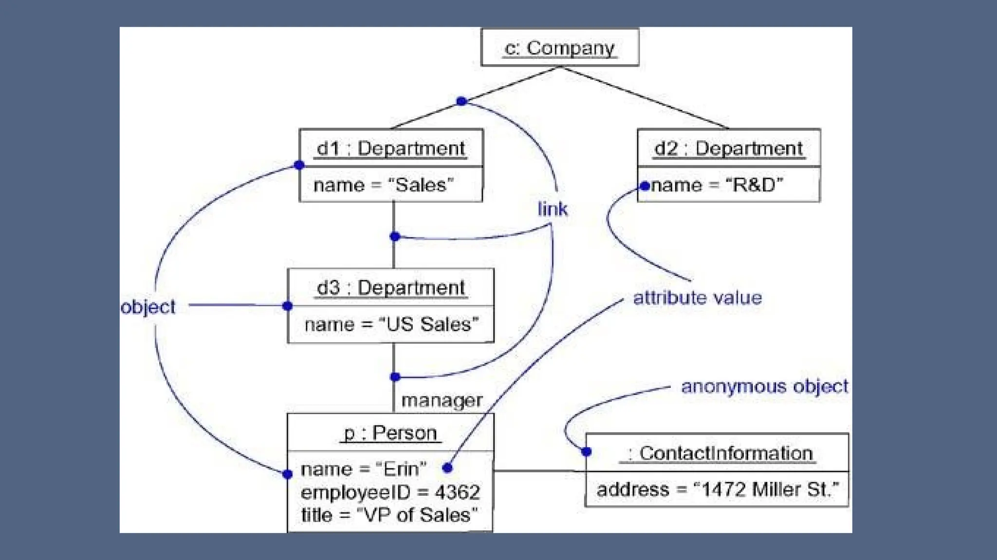
Class & Object Diagrams
Prof. M Nataraja Suresh
Class Diagrams
• Class diagrams are the most common diagram found in modeling
object- oriented systems.
• A class diagram shows a set of classes, interfaces, and collaborations
and their relationships.
• You use class diagrams to model the static design view of a system.
• For the most part, this involves modeling the vocabulary of the
system, modeling collaborations, or modeling schemas.
• Class diagrams are also the foundation for a couple of related
diagrams: component diagrams and deployment diagrams.
• Class diagrams are also important for constructing executable systems
through forward and reverse engineering
Terms and Concepts of Class Diagrams
• Class diagrams commonly contain the following things:
• Classes
• Interfaces
• Collaborations
• Dependency, generalization, and association relationships
• Like all other diagrams, class diagrams may contain notes and
constraints
• Graphically, a class diagram is a collection of vertices and arcs.
• Class diagrams may also contain packages or subsystems, both of
which are used to group elements of your model into larger chunks
Common uses of Class Diagrams
1. To model the vocabulary of a system
Modeling the vocabulary of a system involves making a decision
about which abstractions are a part of the system under consideration
and which fall outside its boundaries.
You use class diagrams to specify these abstractions and their
responsibilities
2. To model simple collaborations
A collaboration is a society of classes, interfaces, and other
elements that work together to provide some cooperative behavior
that's bigger than the sum of all the elements.
Common uses of Class Diagrams
• when you're modeling the semantics of a transaction in a distributed
system, you can't just stare at a single class to understand what's
going on. Rather, these semantics are carried out by a set of classes
that work together. You use class diagrams to visualize and specify
this set of classes and their relationships.
3. To model a logical database schema
Think of a schema as the blueprint for the conceptual design of a
database. In many domains, you'll want to store persistent information
in a relational database or in an object-oriented database. You can
model schemas for these databases using class diagrams.
Common Modeling Techniques- Class Diagrams
Modeling Simple Collaborations No class stands alone. Rather, each
works in collaboration with others to carry out some semantics greater
than each individual
To model a collaboration,
• Identify the mechanism you'd like to model. A mechanism represents
some function or behavior of the part of the system you are modeling
that results from the interaction of a society of classes, interfaces, and
other things.
• For each mechanism, identify the classes, interfaces, and other
collaborations that participate in this collaboration. Identify the
relationships among these things, as well.
Common Modeling Techniques- Class Diagrams
• Use scenarios to walk through these things. Along the way, you'll
discover parts of your model that were missing and parts that were
just plain semantically wrong.
• Be sure to populate these elements with their contents. For classes,
start with getting a good balance of responsibilities. Then, over time,
turn these into concrete attributes and operations.
abstract class
(Motor) with two
concrete children
The diagram with focus only on
those abstractions that are directly
involved in moving the robot.
in a higher-level mechanism for
managing the conflicting goals the
robot might have at a given
moment, the class PathAgent
collaborates with at least two other
classes (Environment and
GoalAgent)
we focus on each of these
collaborations in different diagrams
Driver class
composed of
Steering and
Main motors
One to Many association, one agent
has many sensors
Common Modeling Techniques- Class Diagrams
Modeling a Logical Database Schema
• Many of the systems you'll model will have persistent objects, which
means that they can be stored in a database for later retrieval.
• Most often, you'll use a relational database, an object-oriented
database, or a hybrid object/relational database for persistent
storage.
• The UML is well-suited to modeling logical database schemas, as well
as physical databases themselves
• The UML's class diagrams are a superset of entity-relationship (E-R)
diagrams
Common Modeling Techniques- Class Diagrams
Modeling a Logical Database Schema
• E-R diagrams focus only on data, class diagrams go a step further by
permitting the modeling of behavior, as well.
• In the physical database, these logical operations are generally turned
into triggers or stored procedures.
To model a schema,
• Identify those classes in your model whose state must transcend the
lifetime of their applications. (You want to persist state)
• Create a class diagram that contains these classes and mark them as
persistent (a standard tagged value). You can define your own set of
tagged values to address database-specific details.
Common Modeling Techniques- Class Diagrams
• Expand the structural details of these classes. In general, this means
specifying the details of their attributes and focusing on the associations and
their cardinalities that structure these classes.
• Watch for common patterns that complicate physical database design, such as
cyclic associations, one-to-one associations, and n-ary associations. Where
necessary, create intermediate abstractions to simplify your logical structure.
• Consider also the behavior of these classes by expanding operations that are
important for data access and data integrity. In general, to provide a better
separation of concerns, business rules concerned with the manipulation of
sets of these objects should be encapsulated in a layer above these persistent
classes.
• Where possible, use tools to help you transform your logical design into a
physical design.
association
between Student
and Course
Every student may attend any
number of courses and every
course may have any number of
students
the details of these classes
revealed to a level
sufficient to construct a
physical database
School and Department) expose several
operations for manipulating their parts
Common Modeling Techniques- Class Diagrams
• Forward and Reverse Engineering Forward engineering is the
process of transforming a model into code through a mapping to an
implementation language.
• Forward engineering results in a loss of information, because models
written in the UML are semantically richer than any current object-
oriented programming language.
• In fact, this is a major reason why you need models in addition to
code.
• Structural features, such as collaborations, and behavioral features,
such as interactions, can be visualized clearly in the UML, but not so
clearly from raw code.
Common Modeling Techniques- Class Diagrams
To forward engineer a class diagram,
• Identify the rules for mapping to your implementation language or languages of
choice. This is something you'll want to do for your project or your organization as a
whole.
• Depending on the semantics of the languages you choose, you may have to constrain
your use of certain UML features. For example, the UML permits you to model
multiple inheritance, but Smalltalk permits only single inheritance. You can either
choose to prohibit developers from modeling with multiple inheritance (which makes
your models language-dependent) or develop idioms that transform these richer
features into the implementation language (which makes the mapping more complex).
• Use tagged values to specify your target language. You can do this at the level of
individual classes if you need precise control. You can also do so at a higher level, such
as with collaborations or packages.
• Use tools to forward engineer your models.
Common Modeling Techniques- Class Diagrams
• Reverse Engineering Reverse engineering is the process of
transforming code into a model through a mapping from a specific
implementation language.
• Reverse engineering results in a flood of information, some of which
is at a lower level of detail than you'll need to build useful models.
• At the same time, reverse engineering is incomplete. There is a loss of
information when forward engineering models into code, and so you
can't completely recreate a model from code unless your tools
encode information in the source comments that goes beyond the
semantics of the implementation language.
Common Modeling Techniques- Class Diagrams
To reverse engineer a class diagram,
• Identify the rules for mapping from your implementation language or
languages of choice. This is something you'll want to do for your
project or your organization as a whole.
• Using a tool, point to the code you'd like to reverse engineer. Use your
tool to generate a new model or modify an existing one that was
previously forward engineered.
• Using your tool, create a class diagram by querying the model. For
example, you might start with one or more classes, then expand the
diagram by following specific relationships or other neighboring
classes. Expose or hide details of the contents of this class diagram as
necessary to communicate your intent.
Object Diagrams
• If you have a complex data structure, just looking at the state of one
object at a time doesn't help much.
• Rather, you need to study a snapshot of the object, its neighbors, and
its relationships to these neighbors.
• In all but the simplest object-oriented systems, you'd find a multitude
of objects present, each standing in precise relationship with others.
• In fact, when an object-oriented system breaks, it's typically not
because of a failure in logic, but because of broken connections
among objects or a mangled state in individual objects.
Object Diagrams
• An object diagram covers a set of instances of the things found in a
class diagram.
• An object diagram, therefore, expresses the static part of an
interaction, consisting of the objects that collaborate, but without any
of the messages passed among them.
• In both cases, an object diagram freezes a moment in time
----Object diagrams commonly contain
• Objects
• Links
Like all other diagrams, object diagrams may contain notes and
constraints.
Object Diagrams
• Object diagrams may also contain packages or subsystems
• Sometimes, you'll want to place classes in your object diagrams, as
well, especially when you want to visualize the classes behind each
instance
• An object diagram is essentially an instance of a class diagram or the
static part of an interaction diagram - primarily supporting the
functional requirements of a system - that is, the services the system
should provide to its end users
• Modeling object structures involves taking a snapshot of the objects
in a system at a given moment in time
Common Modeling Techniques- Modeling Object Structures
• when you use object diagrams, you can only meaningfully expose
interesting sets of concrete or prototypical objects. This is what it
means to model an object structure - an object diagram shows one set
of objects in relation to one another at one moment in time.
To model an object structure
• Identify the mechanism you'd like to model. A mechanism represents
some function or behavior of the part of the system you are modeling
that results from the interaction of a society of classes, interfaces, and
other things.
• For each mechanism, identify the classes, interfaces, and other
elements that participate in this collaboration; identify the
relationships among these things, as well.
Common Modeling Techniques- Modeling Object Structures
• Consider one scenario that walks through this mechanism. Freeze that
scenario at a moment in time, and render each object that
participates in the mechanism.
• Expose the state and attribute values of each such object, as
necessary, to understand the scenario.
• Similarly, expose the links among these objects, representing
instances of associations among them.
Robot instance ‘r’ is currently in the state
marked moving
w, an instance of
World, which
represents an
abstraction of the
robot's world
model
instances of
Element, the
robot has
identified but
not yet assigned
in its world view
and are part of
the robot's
global state
Each of these walls is marked with its current width, and each is shown linked to its neighbouring walls, robot
has recognized this enclosed area, which has walls on three sides and a door on the fourth
Common Modeling Techniques- Forward and Reverse
Engineering
Forward Engineering
• Forward engineering (the creation of code from a model) an object diagram is
theoretically possible but pragmatically of limited value.
• In an object-oriented system, instances are things that are created and destroyed
by the application during run time.
• Therefore, you can't exactly instantiate these objects from the outside.
Reverse Engineering
• Reverse engineering (the creation of a model from code) an object diagram is a
very different thing.
• In fact, while you are debugging your system, this is something that you or your
tools will do all the time.
• if you are chasing down a dangling link, you'll want to literally or mentally draw an
object diagram of the affected objects to see where, at a given moment in time, an
object's state or its relationship to other objects is broken
Common Modeling Techniques- Reverse Engineering
To reverse engineer an object diagram,
• Chose the target you want to reverse engineer. Typically, you'll set your context
inside an operation or relative to an instance of one particular class.
• Using a tool or simply walking through a scenario, stop execution at a certain
moment in time.
• Identify the set of interesting objects that collaborate in that context and render
them in an object diagram.
• As necessary to understand their semantics, expose these object's states.
• As necessary to understand their semantics, identify the links that exist among
these objects.
• If your diagram ends up overly complicated, prune it by eliminating objects that
are not germane to the questions about the scenario you need answered.
• If your diagram is too simplistic, expand the neighbors of certain interesting
objects and expose each object's state more deeply.

Object_Oriented_Design_Class and Object Diagrams.pptx

  • 1.
    Class & ObjectDiagrams Prof. M Nataraja Suresh
  • 2.
    Class Diagrams • Classdiagrams are the most common diagram found in modeling object- oriented systems. • A class diagram shows a set of classes, interfaces, and collaborations and their relationships. • You use class diagrams to model the static design view of a system. • For the most part, this involves modeling the vocabulary of the system, modeling collaborations, or modeling schemas. • Class diagrams are also the foundation for a couple of related diagrams: component diagrams and deployment diagrams. • Class diagrams are also important for constructing executable systems through forward and reverse engineering
  • 4.
    Terms and Conceptsof Class Diagrams • Class diagrams commonly contain the following things: • Classes • Interfaces • Collaborations • Dependency, generalization, and association relationships • Like all other diagrams, class diagrams may contain notes and constraints • Graphically, a class diagram is a collection of vertices and arcs. • Class diagrams may also contain packages or subsystems, both of which are used to group elements of your model into larger chunks
  • 5.
    Common uses ofClass Diagrams 1. To model the vocabulary of a system Modeling the vocabulary of a system involves making a decision about which abstractions are a part of the system under consideration and which fall outside its boundaries. You use class diagrams to specify these abstractions and their responsibilities 2. To model simple collaborations A collaboration is a society of classes, interfaces, and other elements that work together to provide some cooperative behavior that's bigger than the sum of all the elements.
  • 6.
    Common uses ofClass Diagrams • when you're modeling the semantics of a transaction in a distributed system, you can't just stare at a single class to understand what's going on. Rather, these semantics are carried out by a set of classes that work together. You use class diagrams to visualize and specify this set of classes and their relationships. 3. To model a logical database schema Think of a schema as the blueprint for the conceptual design of a database. In many domains, you'll want to store persistent information in a relational database or in an object-oriented database. You can model schemas for these databases using class diagrams.
  • 7.
    Common Modeling Techniques-Class Diagrams Modeling Simple Collaborations No class stands alone. Rather, each works in collaboration with others to carry out some semantics greater than each individual To model a collaboration, • Identify the mechanism you'd like to model. A mechanism represents some function or behavior of the part of the system you are modeling that results from the interaction of a society of classes, interfaces, and other things. • For each mechanism, identify the classes, interfaces, and other collaborations that participate in this collaboration. Identify the relationships among these things, as well.
  • 8.
    Common Modeling Techniques-Class Diagrams • Use scenarios to walk through these things. Along the way, you'll discover parts of your model that were missing and parts that were just plain semantically wrong. • Be sure to populate these elements with their contents. For classes, start with getting a good balance of responsibilities. Then, over time, turn these into concrete attributes and operations.
  • 9.
    abstract class (Motor) withtwo concrete children The diagram with focus only on those abstractions that are directly involved in moving the robot. in a higher-level mechanism for managing the conflicting goals the robot might have at a given moment, the class PathAgent collaborates with at least two other classes (Environment and GoalAgent) we focus on each of these collaborations in different diagrams Driver class composed of Steering and Main motors One to Many association, one agent has many sensors
  • 10.
    Common Modeling Techniques-Class Diagrams Modeling a Logical Database Schema • Many of the systems you'll model will have persistent objects, which means that they can be stored in a database for later retrieval. • Most often, you'll use a relational database, an object-oriented database, or a hybrid object/relational database for persistent storage. • The UML is well-suited to modeling logical database schemas, as well as physical databases themselves • The UML's class diagrams are a superset of entity-relationship (E-R) diagrams
  • 11.
    Common Modeling Techniques-Class Diagrams Modeling a Logical Database Schema • E-R diagrams focus only on data, class diagrams go a step further by permitting the modeling of behavior, as well. • In the physical database, these logical operations are generally turned into triggers or stored procedures. To model a schema, • Identify those classes in your model whose state must transcend the lifetime of their applications. (You want to persist state) • Create a class diagram that contains these classes and mark them as persistent (a standard tagged value). You can define your own set of tagged values to address database-specific details.
  • 12.
    Common Modeling Techniques-Class Diagrams • Expand the structural details of these classes. In general, this means specifying the details of their attributes and focusing on the associations and their cardinalities that structure these classes. • Watch for common patterns that complicate physical database design, such as cyclic associations, one-to-one associations, and n-ary associations. Where necessary, create intermediate abstractions to simplify your logical structure. • Consider also the behavior of these classes by expanding operations that are important for data access and data integrity. In general, to provide a better separation of concerns, business rules concerned with the manipulation of sets of these objects should be encapsulated in a layer above these persistent classes. • Where possible, use tools to help you transform your logical design into a physical design.
  • 13.
    association between Student and Course Everystudent may attend any number of courses and every course may have any number of students the details of these classes revealed to a level sufficient to construct a physical database School and Department) expose several operations for manipulating their parts
  • 14.
    Common Modeling Techniques-Class Diagrams • Forward and Reverse Engineering Forward engineering is the process of transforming a model into code through a mapping to an implementation language. • Forward engineering results in a loss of information, because models written in the UML are semantically richer than any current object- oriented programming language. • In fact, this is a major reason why you need models in addition to code. • Structural features, such as collaborations, and behavioral features, such as interactions, can be visualized clearly in the UML, but not so clearly from raw code.
  • 15.
    Common Modeling Techniques-Class Diagrams To forward engineer a class diagram, • Identify the rules for mapping to your implementation language or languages of choice. This is something you'll want to do for your project or your organization as a whole. • Depending on the semantics of the languages you choose, you may have to constrain your use of certain UML features. For example, the UML permits you to model multiple inheritance, but Smalltalk permits only single inheritance. You can either choose to prohibit developers from modeling with multiple inheritance (which makes your models language-dependent) or develop idioms that transform these richer features into the implementation language (which makes the mapping more complex). • Use tagged values to specify your target language. You can do this at the level of individual classes if you need precise control. You can also do so at a higher level, such as with collaborations or packages. • Use tools to forward engineer your models.
  • 17.
    Common Modeling Techniques-Class Diagrams • Reverse Engineering Reverse engineering is the process of transforming code into a model through a mapping from a specific implementation language. • Reverse engineering results in a flood of information, some of which is at a lower level of detail than you'll need to build useful models. • At the same time, reverse engineering is incomplete. There is a loss of information when forward engineering models into code, and so you can't completely recreate a model from code unless your tools encode information in the source comments that goes beyond the semantics of the implementation language.
  • 18.
    Common Modeling Techniques-Class Diagrams To reverse engineer a class diagram, • Identify the rules for mapping from your implementation language or languages of choice. This is something you'll want to do for your project or your organization as a whole. • Using a tool, point to the code you'd like to reverse engineer. Use your tool to generate a new model or modify an existing one that was previously forward engineered. • Using your tool, create a class diagram by querying the model. For example, you might start with one or more classes, then expand the diagram by following specific relationships or other neighboring classes. Expose or hide details of the contents of this class diagram as necessary to communicate your intent.
  • 19.
    Object Diagrams • Ifyou have a complex data structure, just looking at the state of one object at a time doesn't help much. • Rather, you need to study a snapshot of the object, its neighbors, and its relationships to these neighbors. • In all but the simplest object-oriented systems, you'd find a multitude of objects present, each standing in precise relationship with others. • In fact, when an object-oriented system breaks, it's typically not because of a failure in logic, but because of broken connections among objects or a mangled state in individual objects.
  • 20.
    Object Diagrams • Anobject diagram covers a set of instances of the things found in a class diagram. • An object diagram, therefore, expresses the static part of an interaction, consisting of the objects that collaborate, but without any of the messages passed among them. • In both cases, an object diagram freezes a moment in time ----Object diagrams commonly contain • Objects • Links Like all other diagrams, object diagrams may contain notes and constraints.
  • 22.
    Object Diagrams • Objectdiagrams may also contain packages or subsystems • Sometimes, you'll want to place classes in your object diagrams, as well, especially when you want to visualize the classes behind each instance • An object diagram is essentially an instance of a class diagram or the static part of an interaction diagram - primarily supporting the functional requirements of a system - that is, the services the system should provide to its end users • Modeling object structures involves taking a snapshot of the objects in a system at a given moment in time
  • 23.
    Common Modeling Techniques-Modeling Object Structures • when you use object diagrams, you can only meaningfully expose interesting sets of concrete or prototypical objects. This is what it means to model an object structure - an object diagram shows one set of objects in relation to one another at one moment in time. To model an object structure • Identify the mechanism you'd like to model. A mechanism represents some function or behavior of the part of the system you are modeling that results from the interaction of a society of classes, interfaces, and other things. • For each mechanism, identify the classes, interfaces, and other elements that participate in this collaboration; identify the relationships among these things, as well.
  • 24.
    Common Modeling Techniques-Modeling Object Structures • Consider one scenario that walks through this mechanism. Freeze that scenario at a moment in time, and render each object that participates in the mechanism. • Expose the state and attribute values of each such object, as necessary, to understand the scenario. • Similarly, expose the links among these objects, representing instances of associations among them.
  • 25.
    Robot instance ‘r’is currently in the state marked moving w, an instance of World, which represents an abstraction of the robot's world model instances of Element, the robot has identified but not yet assigned in its world view and are part of the robot's global state Each of these walls is marked with its current width, and each is shown linked to its neighbouring walls, robot has recognized this enclosed area, which has walls on three sides and a door on the fourth
  • 26.
    Common Modeling Techniques-Forward and Reverse Engineering Forward Engineering • Forward engineering (the creation of code from a model) an object diagram is theoretically possible but pragmatically of limited value. • In an object-oriented system, instances are things that are created and destroyed by the application during run time. • Therefore, you can't exactly instantiate these objects from the outside. Reverse Engineering • Reverse engineering (the creation of a model from code) an object diagram is a very different thing. • In fact, while you are debugging your system, this is something that you or your tools will do all the time. • if you are chasing down a dangling link, you'll want to literally or mentally draw an object diagram of the affected objects to see where, at a given moment in time, an object's state or its relationship to other objects is broken
  • 27.
    Common Modeling Techniques-Reverse Engineering To reverse engineer an object diagram, • Chose the target you want to reverse engineer. Typically, you'll set your context inside an operation or relative to an instance of one particular class. • Using a tool or simply walking through a scenario, stop execution at a certain moment in time. • Identify the set of interesting objects that collaborate in that context and render them in an object diagram. • As necessary to understand their semantics, expose these object's states. • As necessary to understand their semantics, identify the links that exist among these objects. • If your diagram ends up overly complicated, prune it by eliminating objects that are not germane to the questions about the scenario you need answered. • If your diagram is too simplistic, expand the neighbors of certain interesting objects and expose each object's state more deeply.