Download to read offline
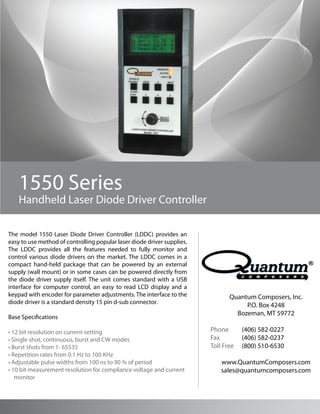
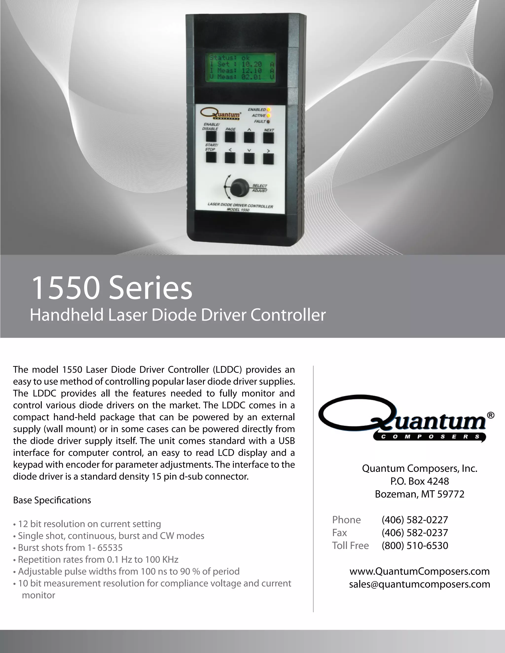

The 1550 Laser Diode Driver Controller (LDDC) provides monitoring and control of laser diode driver supplies in a compact hand-held device. It connects to drivers via a standard 15 pin connector and includes interfaces for computer control via USB, parameter adjustment via keypad and encoder, and readout of operating parameters on an LCD display. The LDDC supports single shot, continuous, burst and CW operation modes with adjustable pulse widths and repetition rates.


![A3918 low voltage dc motor driver allegro datasheet[1]](https://cdn.slidesharecdn.com/ss_thumbnails/a3918lowvoltagedcmotordriverallegro-datasheet1-121031142106-phpapp01-thumbnail.jpg?width=640&height=640&fit=bounds)