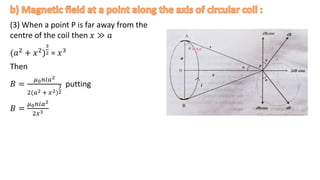
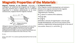
1) Magnets attract iron-containing materials due to their magnetic properties which arise from the alignment of electron spins in their atoms.
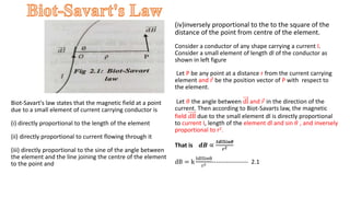
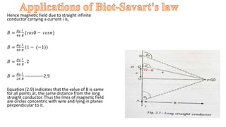
2) Øersted discovered that electric currents produce magnetic fields according to the right-hand rule. Biot-Savart's law describes how the magnetic field is produced by a current-carrying conductor.
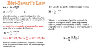
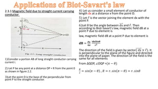
3) Biot-Savart's law states that the magnetic field produced by a current element is directly proportional to the current and length of the element and inversely proportional to the distance from the element. The direction of the magnetic field is perpendicular to both the current element and the line from the element to the point of interest.

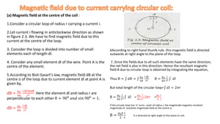
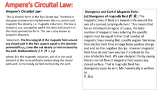
![b) Equivalence between a magnetic shell and current loop
:A magnetic shell is a thin magnet of very small length. If
such a magnetic shell of dipole moment Pm and area of
cross section A is placed in a uniform magnetic field of
induction B, with its cross sectional area parallel to the
field, it is acted upon by a torque T = PmB [Fig. 2.7 (a)].
When a conducting loop of area A is carrying current i and
is held in a uniform magnetic field of induction B with its
plane parallel to the field it is acted upon by a torque T' =
B.A.i. [Fig. 2.7 (b)].
If T = T', then Pm=A.i
.
It gives the equivalence between a current loop and a
magnetic shell. A current loop of area A and carrying current
i is equivalent to a magnetic shell of dipole moment Pm = Ai,
directed perpendicular to the plane of the loop and vice-
versa. Hence, the S.I. unit of magnetic dipole moment is
Amt. Extending this analogy, for a magnet, the dipole
moment (Pm) can be equivalently considered to be due to a
coil wound round the magnet with length as the axis and
carrying current it, called the surface current, Hence Pm = A.i,
by equivalence.
M =
𝑃𝑚
𝑉
=
𝐴.𝑖
𝐴.𝐿
=
𝑖
𝐿
Hence, the intensity of magnetisation is also the surface
current per unit length of the magnet, Hence S.I. unit of M
is
𝐴
𝑚](https://image.slidesharecdn.com/b-230222052158-a8a7b0d6/85/B-Sc-I-Magnetism-pptx-18-320.jpg)
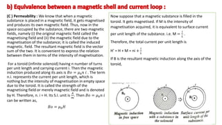
![B =𝜇0𝐻∙ = 𝜇0 𝐻 + 𝑀
B =𝜇0 𝑛𝑖 + 𝑀
as𝑩0 = 𝜇0𝐻 we write B = 𝜇H , by analogy. 𝜇 is called
the permeability of the magnetic material.
𝜇 =
B
𝐻
Therefore, the permeability of a magnetic material is
the ratio of the magnetic induction produced per
unit magnetising field intensity. Its S.1 unit is
weber/Am.
.
Now,
B
𝐵0
=
𝜇𝐻
𝜇0𝐻
=
𝜇
𝜇0
This ratio is called the relative permeability of the material; it
is denoted by 𝜇 or k. Thus, k =
𝜇
𝜇0
Therefore, the relative
permeability of a magnetic substance is defined as the ratio
of the permeability of the substance to the permeability of
free space. It is characteristic of the material.
B =𝜇0 [ni + M] can be written as,
𝝁 H =𝝁𝟎 (H + M)](https://image.slidesharecdn.com/b-230222052158-a8a7b0d6/85/B-Sc-I-Magnetism-pptx-20-320.jpg)
![(d) Magnetic Susceptibility :
(d) Magnetic Susceptibility : It is defined as the
ratio of the intensity of magnetisation induced in the
magnetic substance to the intensity of the magnetic
field. It is denoted by Magnetic susceptibility = X =
𝑴
𝑯
It is also characteristic of the material. For a given
material it also depends upon the temperature (of the
material). Now, from the Eq. (2.42)
𝜇 H=𝜇0(H+M )
𝜇
𝜇0
H=H+M
KH=H+M
K=1+
𝑀
𝐻
K=1+x
.
is characteristic of the material.
B =𝜇0 [ni + M] can be written as,
𝝁 H =𝝁𝟎 (H + M)](https://image.slidesharecdn.com/b-230222052158-a8a7b0d6/85/B-Sc-I-Magnetism-pptx-21-320.jpg)


