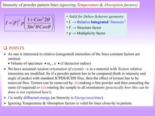
The document discusses scattering from different levels:
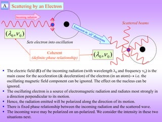
1) Scattering from an electron provides the basis for scattering from larger objects.
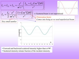
2) Scattering from an atom is the sum of waves scattered by its electrons and depends on atomic number.
3) Scattering from a unit cell is required to understand crystal diffraction patterns, as interference between waves scattered from different atoms in the unit cell determines the intensity of reflections.
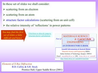
![B Scattering by an Atom
Scattering by an atom [Atomic number, (path
difference suffered by scattering from each e−, )]
Scattering by an atom [Z, (, )]
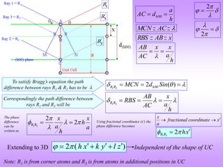
The scattering by an atom is the sum (vectoral sum, including phase) of the waves scatted by
the electrons. Angular differences involved in scattering leads to path differences.
In the forward direction all scattered waves are in phase.
The scattering from an atom is captured in the atomic scattering factor (f), which is the ratio of
the amplitude of the wave scattered by the atom to that scattered by a single electron. It shows
the amplification obtained by the presence of multiple electrons in an atom.
Scattering by an atom is proportional to the atomic number (the number of electrons). The
natural coordinates to plot the variation of ‘f’ is not or 2, but Sin()/. At 0 the curve starts
at the atomic number as in the schematic below.
electron
an
by
scattered
wave
of
Amplitude
atom
an
by
scattered
wave
of
Amplitude
Factor
Scattering
Atomic
f
f
→
)
(
Sin
(Å−1) →
0.2 0.4 0.6 0.8 1.0
10
20
30
Schematic showing variation in
atomic scattering factor with
Sin()/
)
(
Sin
Atomic Scattering Factor or Form Factor (f)
Equals number of electrons, say for
f = 29, it should Cu or Zn+
Coherent
scattering
Incoherent (Compton)
scattering
Z
Sin() /
As θ↓, path difference ↓ constructive interference
As λ↓, path difference ↑ destructive interference](https://image.slidesharecdn.com/structurefactorcalculations-230211153010-09f1672e/85/structure_factor_calculations-ppt-8-320.jpg)
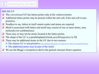
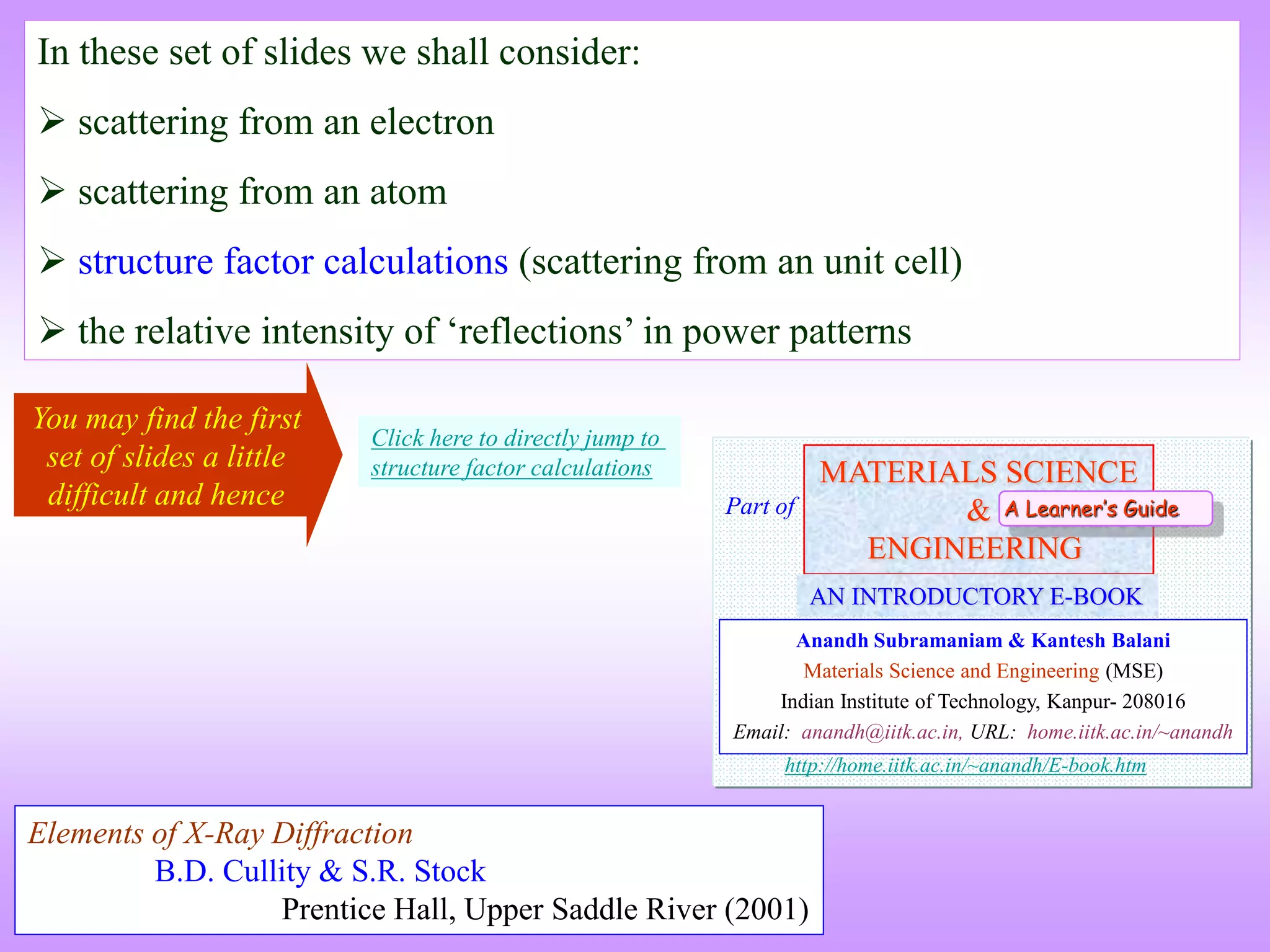
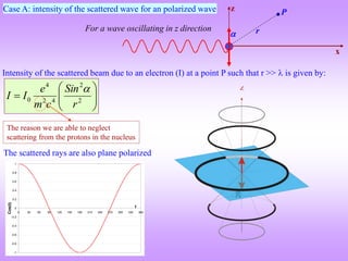
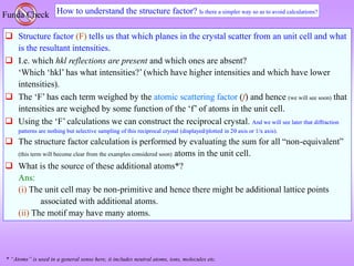
![ If atom B is different from atom A the amplitudes must be weighed by the respective
atomic scattering factors (f).
The resultant amplitude of all the waves scattered by all the atoms (say ‘n’atoms) in the UC
gives the scattering factor for the unit cell .
The unit cell scattering factor is called the Structure Factor (F).
The intensity of the ‘diffracted’wave is proportional to the square of F.
Once we have the structure factor then the intensity obtained from a set of planes (hkl) is
known.
Scattering by an unit cell = f(position of the atoms, atomic scattering factors)
electron
an
by
scattered
wave
of
Amplitude
uc
in
atoms
all
by
scattered
wave
of
Amplitude
Factor
Structure
F
[2 ( )]
i i h x k y l z
E Ae fe
2 ( )
h x k y l z
The phase difference gives rise to the amplitude (which can be written in complex notation as)
2
F
I
[2 ( )]
1 1
j j j j
n n
i i h x k y l z
hkl
n j j
j j
F f e f e
Structure factor is independent of the shape and size of the unit cell!
F → Fhkl
For n atoms in the UC
If the UC distorts so do the planes in it!!
hkl
n
F](https://image.slidesharecdn.com/structurefactorcalculations-230211153010-09f1672e/85/structure_factor_calculations-ppt-13-320.jpg)
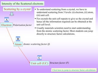
![n
ni
e )
1
(
)
(
2
Cos
e
e i
i
ni
ni
e
e
1
)
(
i
n
odd
e
1
)
(
i
n
even
e
( 1)
n i n
e
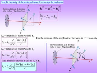
Note:
n i n i
e e
n is an integer
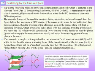
Some useful relations
[2 ( )]
1 1
j j j j
n n
i i h x k y l z
hkl
n j j
j j
F f e f e
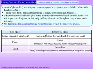
The summation ‘j’ is done over the ‘n’ atoms in the UC.
In a primiteve unit cell (e.g. in the SC crystal) there is just one atom
(in the UC).
x’(y’& z’) refer(s) to the fractional coordinates of each atom.
The fj is the atomic scattering factor for each atom. If there is just
one type of atom (say Po then fj = fPo). If there is more than one type
of atom, the fractional coordinates should match with the atom type.
The intensity is an actual observable (if sampled in an experiment) and hence
structure factor is a real quantity.
A set of useful equations to evaluate the F is given on the right side.
Evaluation of the equation](https://image.slidesharecdn.com/structurefactorcalculations-230211153010-09f1672e/85/structure_factor_calculations-ppt-14-320.jpg)

![[2 ( )]
j j j j
i i h x k y l z
hkl
j j
F f e f e
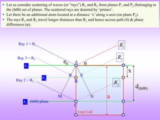
[2 ( 0 0 0)] 0
i h k l
F f e f e f
2
2
f
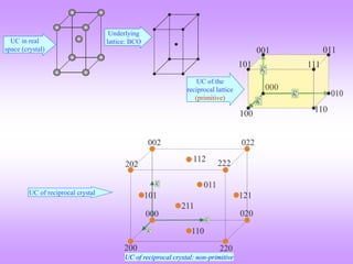
F F is independent of the scattering plane (h k l)
All reflections are
present
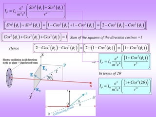
We note that in simple cubic crystals
there is no restrictions on the allowed
values of hkl (i.e. for all values of hkl
reflections are present).
1/a
1/a
1/a
The diameter of the
sphere scales with the
intensity of the ‘spot’.
UC of reciprocal crystal
(intensities decorating the reciprocal lattice)
(also primitive)
In the reciprocal crystal, intensities decorate the lattice points (shown in orange colour). The magnitude of
the intensity (as determined from the structure factor calculation) is f2.](https://image.slidesharecdn.com/structurefactorcalculations-230211153010-09f1672e/85/structure_factor_calculations-ppt-18-320.jpg)
![2 Atom at (0,0,0) & (½, ½, 0) and equivalent positions
[2 ( )]
j j j j
i i h x k y l z
j j
F f e f e
]
1
[ )
(
)
(
)
(
)]
2
(
2
[
)]
2
(
2
[
)]
2
(
2
[
)]
0
(
2
[
h
l
i
l
k
i
k
h
i
h
l
i
l
k
i
k
h
i
i
e
e
e
f
e
e
e
e
f
F
Face Centred Cubic (CCP crystal)
Real
f
F 4
0
F
2
2
16 f
F
0
2
F
(h, k, l) unmixed
(h, k, l) mixed
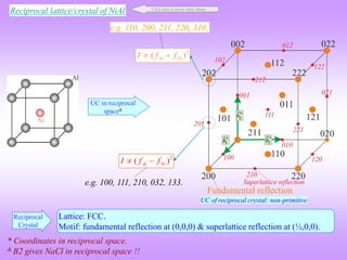
111, 200, 220, 333, 420
100, 211; 210, 032, 033
(½, ½, 0), (½, 0, ½), (0, ½, ½)
]
1
[ )
(
)
(
)
( h
l
i
l
k
i
k
h
i
e
e
e
f
F
Two odd and one even (e.g. 112); two even and one odd (e.g. 122)
h,k,l → all even or all odd
CCP (“FCC crystal”)
becomes “BCC crystal” in
reciprocal space
Continued…
UC of reciprocal crystal: non-primitive](https://image.slidesharecdn.com/structurefactorcalculations-230211153010-09f1672e/85/structure_factor_calculations-ppt-19-320.jpg)
![Mixed indices CASE h k l
A o o e
B o e e
( ) ( ) ( )
CASE A: [1 ] [1 1 1 1] 0
i e i o i o
e e e
( ) ( ) ( )
CASE B: [1 ] [1 1 1 1] 0
i o i e i o
e e e
0
F 0
2
F
(h, k, l) mixed e.g. 100, 211; 210, 032, 033.
Mixed indices Two odd and one even (e.g. 112); two even and one odd (e.g. 122)
Unmixed indices CASE h k l
A o o o
B e e e
Unmixed indices
f
F 4
2
2
16 f
F
(h, k, l) unmixed
e.g. 111, 200, 220, 333, 420.
All odd (e.g. 111); all even (e.g. 222)
( ) ( ) ( )
CASE A: [1 ] [1 1 1 1] 4
i e i e i e
e e e
( ) ( ) ( )
CASE B: [1 ] [1 1 1 1] 4
i e i e i e
e e e
This implies that in FCC only h,k,l
‘unmixed’ reflections are present.
Face Centred Cubic](https://image.slidesharecdn.com/structurefactorcalculations-230211153010-09f1672e/85/structure_factor_calculations-ppt-20-320.jpg)
![3 Atom at (0,0,0) & (½, ½, ½) and equivalent positions
[2 ( )]
j j j j
i i h x k y l z
j j
F f e f e
1 1 1
[2 ( )]
[2 ( 0 0 0)] 2 2 2
[ 2 ( )]
0 ( )
2
[1 ]
i h k l
i h k l
h k l
i
i h k l
F f e f e
f e f e f e
Body centred Orthorhombic
Real
]
1
[ )
( l
k
h
i
e
f
F
f
F 2
0
F
2
2
4 f
F
0
2
F
e.g. 110, 200, 211; 220, 022, 310.
e.g. 100, 001, 111; 210, 032, 133.
This implies that (h+k+l) even reflections are only present.
The situation is identical in BCC crystals as well.
Continued…
UC in real
space (crystal)](https://image.slidesharecdn.com/structurefactorcalculations-230211153010-09f1672e/85/structure_factor_calculations-ppt-21-320.jpg)
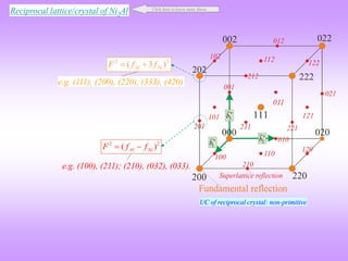
![4 Atoms at (0,0,0) & (½, ½, 0) and equivalent positions
[2 ( )]
j j j j
i i h x k y l z
hkl
j j
F f e f e
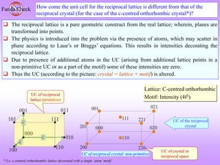
C- centred Orthorhombic Crystal
For this case there is one additional lattice point with an associated atom. Hence, there will be
two terms in the summation for the structure factor.
UC of the
reciprocal lattice
(primitive)
Ball & stick model of UC in real space
UC in real
space (crystal)
This is a UC of the reciprocal lattice. The UC
corresponds to a simple orthorhombic lattice
in reciprocal space.
Note the basis vectors.
The magnitude of the basis vectors are 1/a,
1/b & 1/c.
However, the reciprocal crystal has a
different unit cell.
Unit cell of the reciprocal crystal (as we shall see)
is a c-centred orthorhombic UC (i.e. UC usually
chosen for the c-centred orthorhombic lattice).
*
1
1
| |
b
a
*
2
1
| |
b
b
*
3
1
| |
b
c
](https://image.slidesharecdn.com/structurefactorcalculations-230211153010-09f1672e/85/structure_factor_calculations-ppt-23-320.jpg)
![1 1
[2 ( 0)]
[2 ( 0 0 0)] 2 2
[ 2 ( )]
0 ( )
2
[1 ]
i h k l
hkl i h k l
h k
i
i h k
F f e f e
f e f e f e
F is independent of the ‘l’index
Real
]
1
[ )
( k
h
i
e
f
F
f
F 2
0
F
2
2
4 f
F
0
2
F
e.g. 001, 110, 112; 021, 022, 023.
e.g. 100, 101, 102; 031, 032, 033.
Important note:
The 100, 101, 210, etc. points in
the reciprocal lattice exist (as the
corresponding real lattice planes
exist), however the intensity
decorating these points is zero.
1/a 1/b
1/c
Missing reflections Unit cell of reciprocal
lattice (primitive)
C-centred orthorhombic UC
UC of reciprocal crystal: non-primitive](https://image.slidesharecdn.com/structurefactorcalculations-230211153010-09f1672e/85/structure_factor_calculations-ppt-24-320.jpg)
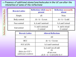
![ If the blue planes are scattering in phase then on C-
centering the red planes will scatter out of phase (with
the blue planes- as they bisect them) and hence the
(210) reflection will become extinct
This analysis is consistent with the extinction rules: (h
+ k) odd is absent
The result derived (i.e. the effect of lattice centring) can be understood by a simple geometric consideration. This is
illustrated for the C-centred OR crystal considered before, but is valid for all crystals.
Let us view the [001] projection of the crystal and consider two sets of planes: (210) and (310) planes.
On introducing a centring a new set of lattice planes between the original (210) planes have to be introduced, which
scatter exactly out of phase with the original planes and hence the 210 reflection goes missing on introducing a C-
centring. In the case of the (310) planes no new planes need to be introduced and this reflection survives.
In case of the (310) planes no new translationally
equivalent planes are added on lattice centering this
reflection cannot go missing.
This analysis is consistent with the extinction rules: (h
+ k) even is present](https://image.slidesharecdn.com/structurefactorcalculations-230211153010-09f1672e/85/structure_factor_calculations-ppt-25-320.jpg)
![F SC, Al at (0, 0, 0), Ni at (½, ½, ½) NiAl: Simple Cubic (B2- ordered structure)
SC
1 1 1
[2 ( )]
[2 ( 0 0 0)] 2 2 2
[ 2 ( )]
0 [ ]
2
i h k l
i h k l
Al Ni
h k l
i
i h k l
Al Ni Al Ni
F f e f e
f e f e f f e
Real
Al Ni
F f f
e.g. 110, 200, 211, 220, 310.
e.g. 100, 111, 210, 032, 133.
[ ]
i h k l
Al Ni
F f f e
2 2
( )
Al Ni
F f f
Al Ni
F f f
2 2
( )
Al Ni
F f f
Click here to know more about ordered structures
When the central atom is identical to the corner ones we have the BCC case.
This implies that (h+k+l) even reflections are only present in BCC.
This term is zero for BCC](https://image.slidesharecdn.com/structurefactorcalculations-230211153010-09f1672e/85/structure_factor_calculations-ppt-27-320.jpg)
![G FCC, C at (0,0,0) & (¼, ¼, ¼)
[2 ( )]
[2 ( 0)] 4
( ) ( ) ( )
[ ]
h k l
i
i
C C
i h k i k l i l h
Al Ni
F f e f e
f f e e e
Diamond Cubic
Real
(h, k, l) unmixed
(h, k, l) mixed
(111), (200), (220), (333), (420)
(100), (211); (210), (032), (033)
Two odd and one even (e.g. 112); two even and one odd (e.g. 122)
Ni
Al
( ) ( ) ( )
[ ]
i h k i k l i l h
Al Ni
F f f e e e
3
Al Ni
F f f
2 2
( 3 )
Al Ni
F f f
Al Ni
F f f
2 2
( )
Al Ni
F f f
h,k,l → all even or all odd](https://image.slidesharecdn.com/structurefactorcalculations-230211153010-09f1672e/85/structure_factor_calculations-ppt-29-320.jpg)
![G SC, Al at (0,0,0), Ni at (½, ½, 0) and equivalent positions
[2 ( )] [2 ( )] [2 ( )]
[2 ( 0)] 2 2 2
( ) ( ) ( )
[ ]
h k k l l h
i i i
i
Al Ni
i h k i k l i l h
Al Ni
F f e f e e e
f f e e e
Simple Cubic (L12 ordered structure)
Real
(h, k, l) unmixed
(h, k, l) mixed
(111), (200), (220), (333), (420)
(100), (211); (210), (032), (033)
(½, ½, 0), (½, 0, ½), (0, ½, ½)
Two odd and one even (e.g. 112); two even and one odd (e.g. 122)
Ni
Al
( ) ( ) ( )
[ ]
i h k i k l i l h
Al Ni
F f f e e e
3
Al Ni
F f f
2 2
( 3 )
Al Ni
F f f
Al Ni
F f f
2 2
( )
Al Ni
F f f
h,k,l → all even or all odd
Click here to know more about ordered structures](https://image.slidesharecdn.com/structurefactorcalculations-230211153010-09f1672e/85/structure_factor_calculations-ppt-30-320.jpg)
![E Na+ at (0,0,0) + Face Centering Translations (½, ½, 0), (½, 0, ½), (0, ½, ½)
Cl− at (½, 0, 0) + FCT (0, ½, 0), (0, 0, ½), (½, ½, ½)
)]
2
(
2
[
)]
2
(
2
[
)]
2
(
2
[
)]
2
(
2
[
)]
2
(
2
[
)]
2
(
2
[
)]
2
(
2
[
)]
0
(
2
[
l
k
h
i
l
i
k
i
h
i
Cl
h
l
i
l
k
i
k
h
i
i
Na
e
e
e
e
f
e
e
e
e
f
F
]
[
]
1
[
)
(
)
(
)
(
)
(
)
(
)
(
)
(
l
k
h
i
l
i
k
i
h
i
Cl
h
l
i
l
k
i
k
h
i
Na
e
e
e
e
f
e
e
e
f
F
]
1
[
]
1
[
)
(
)
(
)
(
)
(
)
(
)
(
)
(
k
h
i
h
l
i
l
k
i
l
k
h
i
Cl
h
l
i
l
k
i
k
h
i
Na
e
e
e
e
f
e
e
e
f
F
]
1
][
[ )
(
)
(
)
(
)
( h
l
i
l
k
i
k
h
i
l
k
h
i
Cl
Na
e
e
e
e
f
f
F
NaCl: FCC lattice](https://image.slidesharecdn.com/structurefactorcalculations-230211153010-09f1672e/85/structure_factor_calculations-ppt-32-320.jpg)
![]
1
][
[ )
(
)
(
)
(
)
( h
l
i
l
k
i
k
h
i
l
k
h
i
Cl
Na
e
e
e
e
f
f
F
Zero for mixed indices
Mixed indices CASE h k l
A o o e
B o e e
]
2
][
1
[
Term
Term
F
( ) ( ) ( )
CASEA: 2 [1 ] [1 1 1 1] 0
i e i o i o
Term e e e
0
]
1
1
1
1
[
]
1
[
2
:
B
CASE )
(
)
(
)
(
o
i
e
i
o
i
e
e
e
Term
0
F 0
2
F
(h, k, l) mixed 100, 211; 210, 032, 033
Mixed indices
NaCl: FCC lattice
Unmixed indices CASE h k l
A o o o
B e e e
4
]
1
1
1
1
[
]
1
[
2
:
A
CASE )
(
)
(
)
(
e
i
e
i
e
i
e
e
e
Term
4
]
1
1
1
1
[
]
1
[
2
:
B
CASE )
(
)
(
)
(
e
i
e
i
e
i
e
e
e
Term
Unmixed indices
Continued…](https://image.slidesharecdn.com/structurefactorcalculations-230211153010-09f1672e/85/structure_factor_calculations-ppt-33-320.jpg)
![(h, k, l) unmixed ]
[
4 )
( l
k
h
i
Cl
Na
e
f
f
F
]
[
4
Cl
Na
f
f
F If (h + k + l) is even
2 2
16[ ]
Na Cl
f I
F f
]
[
4
Cl
Na
f
f
F If (h + k + l) is odd
2 2
16[ ]
Na Cl
f I
F f
111, 222; 133, 244
222, 244
111, 133
h,k,l → all even or all odd
NaCl: FCC lattice
UC in reciprocal
space*
* NaCl gives B2 in reciprocal space !!
UC of reciprocal crystal: non-primitive](https://image.slidesharecdn.com/structurefactorcalculations-230211153010-09f1672e/85/structure_factor_calculations-ppt-34-320.jpg)
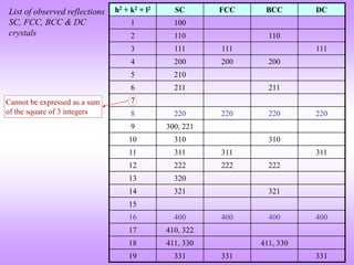
![Multiplicity factor
Lattice Index Multiplicity Planes
Cubic
(with highest
symmetry)
(100) 6 [(100) (010) (001)] ( 2 for negatives)
(110) 12 [(110) (101) (011), (110) (101) (011)] ( 2 for negatives)
(111) 12 [(111) (111) (111) (111)] ( 2 for negatives)
(210) 24* (210) 3! Ways, (210) 3! Ways,
(210) 3! Ways, (210) 3! Ways
(211) 24
(211) 3 ways, (211) 3! ways,
(211) 3 ways
(321) 48*
Tetragonal
(with highest
symmetry)
(100) 4 [(100) (010)] ( 2 for negatives)
(110) 4 [(110) (110)] ( 2 for negatives)
(111) 8 [(111) (111) (111) (111)] ( 2 for negatives)
(210) 8* (210) = 2 Ways, (210) = 2 Ways,
(210) = 2 Ways, (210) = 2 Ways
(211) 16 [Same as for (210) = 8] 2 (as l can be +1 or 1)
(321) 16* Same as above (as last digit is anyhow not permuted)
* Altered in crystals with lower symmetry
Actually only 3 planes ! (as (hkl) (h k l)](https://image.slidesharecdn.com/structurefactorcalculations-230211153010-09f1672e/85/structure_factor_calculations-ppt-39-320.jpg)
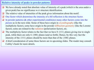
![All peaks present
Look at general trend line!
0
5
10
15
20
25
30
0 20 40 60 80
Bragg Angle (, degrees)
Lorentz-Polarization
factor
Polarization factor
2
1
2
1
Sin
Cos
Sin
factor
Lorentz
2
1 2
Cos
IP
Cos
Sin
Cos
factor
on
Polarizati
Lorentz 2
2
2
1
XRD pattern from Polonium
Click here for details
Example of effect of Polarization factor on
power pattern
The polarization factor and the Lorentz factor both have ‘’ dependence (only) can be combined into the
L-P factor. Note that the LP factor has a dip in middle 2 values (with large values at low and high
angles). [Fig.1].
The signature of this factor is evident in the powder diffraction pattern from Po (simple cubic) as shown
in Fig.2.
Fig.2
Fig.1
Lorentz factor](https://image.slidesharecdn.com/structurefactorcalculations-230211153010-09f1672e/85/structure_factor_calculations-ppt-41-320.jpg)