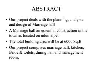
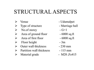
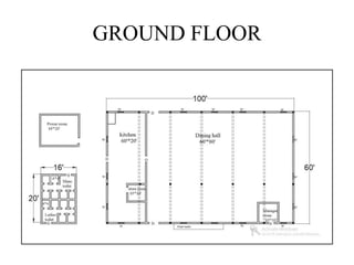
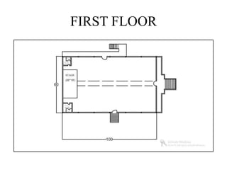
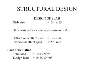
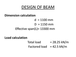
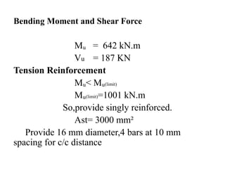
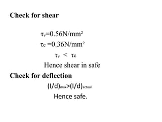
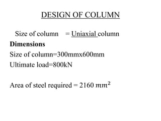
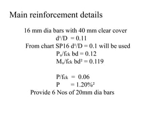
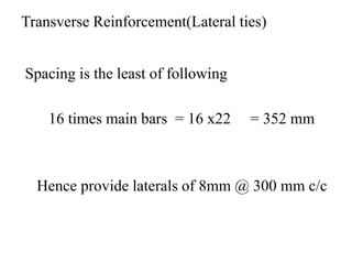
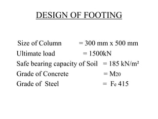
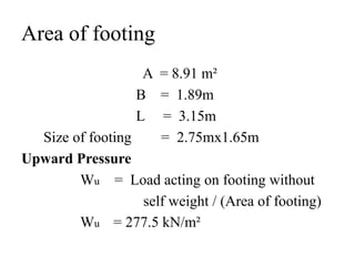
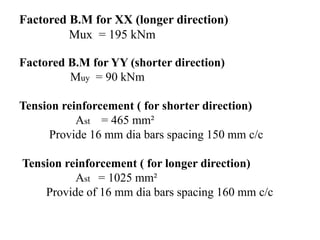
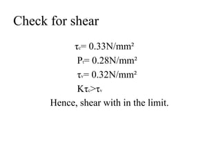
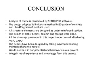
CONTENTS
Abstract of the Project
Methodology
Introduction
Planning Details
Structural Designs
Conclusion
ABSTRACT
• Our project deals with the planning, analysis
and design of Marriage hall
• A Marriage hall an essential construction in the
town as located on udumalpet.
• The total building area will be at 6000 Sq.ft
• Our project comprises marriage hall, kitchen,
Bride & toilets, dining hall and management
room.
INTRODUCTION
• A building should be planned to make it
comfortable, economical and to meet all the
requirements of the dwellers.
• Functionality, utility, cost, habits, taste and
requirements.It should also be considered in
planning a building.
• The planning of this commercial building is so
planned to meet out all the above factors.
STRUCTURAL ASPECTS
 Venue - Udumalpet
 Type of structure - Marriage hall
 No.of storey - G+1
 Area of ground floor - 6000 sq.ft
 Area of first floor - 6000 sq.ft
 Floor height - 3m
 Outer wall thickness - 230 mm
 Partition wall thickness - 115 mm
 Material grade - M20 ,Fe415
PLANNING DETAILS
GROUND FLOOR
FIRST FLOOR
STRUCTURAL DESIGN
DESIGN OF SLAB
Slab size = 5m x 13m
It is designed as a one way continuous slab
Effective depth of slab = 195 mm
Overall depth of span = 220 mm
Load Calculation
Total load = 10.5 kN/m²
Design load = 15.75 kN/m²
Reinforcement Details
Ast = 1134.27 mm²
Provide 20mm dia bars at 270 mm spacing c/c
Nominal Shear force
τᵥ = 0.18 N/mm²
τc = 0.48 N/mm²
Ks * τc>τᵥ
Hence safe in shear
Check for Deflection
deff < d
Hence the deflection is Safe
DESIGN OF BEAM
Dimension calculation
d = 1100 mm
D = 1150 mm
Effective span(L)= 13300 mm
Load calculation
Total load = 28.25 kN/m
Factored load = 42.5 kN/m
Bending Moment and Shear Force
Mᵤ = 642 kN.m
Vu = 187 KN
Tension Reinforcement
Mᵤ< Mᵤ(limit)
Mᵤ(limit)=1001 kN.m
So,provide singly reinforced.
Ast= 3000 mm²
Provide 16 mm diameter,4 bars at 10 mm
spacing for c/c distance
Check for shear
τᵥ=0.56N/mm²
τc =0.36N/mm²
τᵥ < τc
Hence shear in safe
Check for deflection
(I/d)max>(I/d)actual
Hence safe.
DESIGN OF COLUMN
Size of column = Uniaxial column
Dimensions
Size of column=300mmx600mm
Ultimate load=800kN
Area of steel required = 2160 𝑚𝑚2
Main reinforcement details
16 mm dia bars with 40 mm clear cover
d¹/D = 0.11
From chart SP16 d¹/D = 0.1 will be used
Pᵤ/fck bd = 0.12
Mᵤ/fck bd² = 0.119
P/fck = 0.06
P = 1.20%²
Provide 6 Nos of 20mm dia bars
Transverse Reinforcement(Lateral ties)
Spacing is the least of following
16 times main bars = 16 x22 = 352 mm
Hence provide laterals of 8mm @ 300 mm c/c
DESIGN OF FOOTING
Size of Column = 300 mm x 500 mm
Ultimate load = 1500kN
Safe bearing capacity of Soil = 185 kN/m²
Grade of Concrete = M20
Grade of Steel = Fe 415
Area of footing
A = 8.91 m²
B = 1.89m
L = 3.15m
Size of footing = 2.75mx1.65m
Upward Pressure
Wu = Load acting on footing without
self weight / (Area of footing)
Wu = 277.5 kN/m²
Factored B.M for XX (longer direction)
Mux = 195 kNm
Factored B.M for YY (shorter direction)
Muy = 90 kNm
Tension reinforcement ( for shorter direction)
Ast = 465 mm²
Provide 16 mm dia bars spacing 150 mm c/c
Tension reinforcement ( for longer direction)
Ast = 1025 mm²
Provide of 16 mm dia bars spacing 160 mm c/c
Check for shear
τc= 0.33N/mm²
Pt= 0.28N/mm²
τv= 0.32N/mm²
Kτc>τv
Hence, shear with in the limit.
CONCLUSION
• Analysis of frame is carried out by STADD PRO software.
• The design adopted is limit state method M20 grade of concrete
and Fe 415 grade of steel are used.
• All structural elements are designed as under reinforced section.
• The design of slabs, beams, column and footing were done.
• All the drawings presented in this project report was drafted using
AUTO CADD
• The beams have been designed by taking maximum bending
moment of analysis results.
• We do our best in our potential and hard work in our project.
• We gain lot of experience and knowledge form this project.
THANK YOU

6.pptx

  • 1.
    CONTENTS Abstract of theProject Methodology Introduction Planning Details Structural Designs Conclusion
  • 2.
    ABSTRACT • Our projectdeals with the planning, analysis and design of Marriage hall • A Marriage hall an essential construction in the town as located on udumalpet. • The total building area will be at 6000 Sq.ft • Our project comprises marriage hall, kitchen, Bride & toilets, dining hall and management room.
  • 3.
    INTRODUCTION • A buildingshould be planned to make it comfortable, economical and to meet all the requirements of the dwellers. • Functionality, utility, cost, habits, taste and requirements.It should also be considered in planning a building. • The planning of this commercial building is so planned to meet out all the above factors.
  • 4.
    STRUCTURAL ASPECTS  Venue- Udumalpet  Type of structure - Marriage hall  No.of storey - G+1  Area of ground floor - 6000 sq.ft  Area of first floor - 6000 sq.ft  Floor height - 3m  Outer wall thickness - 230 mm  Partition wall thickness - 115 mm  Material grade - M20 ,Fe415
  • 5.
  • 6.
  • 7.
  • 8.
    STRUCTURAL DESIGN DESIGN OFSLAB Slab size = 5m x 13m It is designed as a one way continuous slab Effective depth of slab = 195 mm Overall depth of span = 220 mm Load Calculation Total load = 10.5 kN/m² Design load = 15.75 kN/m²
  • 9.
    Reinforcement Details Ast =1134.27 mm² Provide 20mm dia bars at 270 mm spacing c/c
  • 10.
    Nominal Shear force τᵥ= 0.18 N/mm² τc = 0.48 N/mm² Ks * τc>τᵥ Hence safe in shear Check for Deflection deff < d Hence the deflection is Safe
  • 11.
    DESIGN OF BEAM Dimensioncalculation d = 1100 mm D = 1150 mm Effective span(L)= 13300 mm Load calculation Total load = 28.25 kN/m Factored load = 42.5 kN/m
  • 12.
    Bending Moment andShear Force Mᵤ = 642 kN.m Vu = 187 KN Tension Reinforcement Mᵤ< Mᵤ(limit) Mᵤ(limit)=1001 kN.m So,provide singly reinforced. Ast= 3000 mm² Provide 16 mm diameter,4 bars at 10 mm spacing for c/c distance
  • 13.
    Check for shear τᵥ=0.56N/mm² τc=0.36N/mm² τᵥ < τc Hence shear in safe Check for deflection (I/d)max>(I/d)actual Hence safe.
  • 14.
    DESIGN OF COLUMN Sizeof column = Uniaxial column Dimensions Size of column=300mmx600mm Ultimate load=800kN Area of steel required = 2160 𝑚𝑚2
  • 15.
    Main reinforcement details 16mm dia bars with 40 mm clear cover d¹/D = 0.11 From chart SP16 d¹/D = 0.1 will be used Pᵤ/fck bd = 0.12 Mᵤ/fck bd² = 0.119 P/fck = 0.06 P = 1.20%² Provide 6 Nos of 20mm dia bars
  • 16.
    Transverse Reinforcement(Lateral ties) Spacingis the least of following 16 times main bars = 16 x22 = 352 mm Hence provide laterals of 8mm @ 300 mm c/c
  • 17.
    DESIGN OF FOOTING Sizeof Column = 300 mm x 500 mm Ultimate load = 1500kN Safe bearing capacity of Soil = 185 kN/m² Grade of Concrete = M20 Grade of Steel = Fe 415
  • 18.
    Area of footing A= 8.91 m² B = 1.89m L = 3.15m Size of footing = 2.75mx1.65m Upward Pressure Wu = Load acting on footing without self weight / (Area of footing) Wu = 277.5 kN/m²
  • 19.
    Factored B.M forXX (longer direction) Mux = 195 kNm Factored B.M for YY (shorter direction) Muy = 90 kNm Tension reinforcement ( for shorter direction) Ast = 465 mm² Provide 16 mm dia bars spacing 150 mm c/c Tension reinforcement ( for longer direction) Ast = 1025 mm² Provide of 16 mm dia bars spacing 160 mm c/c
  • 20.
    Check for shear τc=0.33N/mm² Pt= 0.28N/mm² τv= 0.32N/mm² Kτc>τv Hence, shear with in the limit.
  • 21.
    CONCLUSION • Analysis offrame is carried out by STADD PRO software. • The design adopted is limit state method M20 grade of concrete and Fe 415 grade of steel are used. • All structural elements are designed as under reinforced section. • The design of slabs, beams, column and footing were done. • All the drawings presented in this project report was drafted using AUTO CADD • The beams have been designed by taking maximum bending moment of analysis results. • We do our best in our potential and hard work in our project. • We gain lot of experience and knowledge form this project.
  • 22.