
Recommended
Recommended
More Related Content
What's hot
What's hot (16)
Similar to Design of Solar Car Chassis
Similar to Design of Solar Car Chassis (20)
More from ijtsrd
More from ijtsrd (20)
Recently uploaded
Recently uploaded (20)
Design of Solar Car Chassis
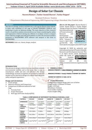
- 1. International Journal of Trend in Scientific Research and Development (IJTSRD) Volume 4 Issue 3, April 2020 Available Online: www.ijtsrd.com e-ISSN: 2456 – 6470 @ IJTSRD | Unique Paper ID – IJTSRD30723 | Volume – 4 | Issue – 3 | March-April 2020 Page 936 Design of Solar Car Chassis Naveen Kumar1, Tushar Anand Sharan2, Tushar Rajput2 1Assistant Professor, 2Student, 1,2Department of Mechanical Engineering, ABES Engineering College, Ghaziabad, Uttar Pradesh, India ABSTRACT The aim is to design, analyze and fabricate a roll cageforElectricSolarVehicle. It deals with modeling of roll cage of SOLAR POWERED VEHICLE and analyzing it to give an optimum design. The main objective of this research work is to perform analysis (structural) on our frame considering the safety and ergonomics of driver during any collision or accident, to have a compact frame with less weight and with good asthetics as well. The structuremodel is prepared in SOLIDWORKS 2018 software and analysis is also done in SOLDWORKS. KEYWORDS: Solar car, chassis, design, analysis How to cite this paper: Naveen Kumar | Tushar Anand Sharan | Tushar Rajput "Design of Solar Car Chassis" Published in International Journal of Trend in Scientific Research and Development (ijtsrd), ISSN: 2456- 6470, Volume-4 | Issue-3, April 2020, pp.936-939, URL: www.ijtsrd.com/papers/ijtsrd30723.pdf Copyright © 2020 by author(s) and International Journal ofTrendinScientific Research and Development Journal. This is an Open Access article distributed under the terms of the Creative CommonsAttribution License (CC BY 4.0) (http://creativecommons.org/licenses/by /4.0) INTRODUCTION The aim was to design a vehicle that can contribute towards environmental stability and at the same time is easy to manufacture, stable and also cost effective. The design methodology involved recognition of customer’s need and market survey that led to design of a vehicle with adequate safety and good ergonomics. Design and Calculations: Frame design Material selection and Comparison Comparison of different material for Roll Cage 1. Formula Used 2. Frame Dimension 3. Roll cage and Frame Analysis(FEA) FORMULA USED :- 1. Frame Dimension: Configuration tadpole design specs are as below: Length*width =2185mm*1474mm Height =1397mm Wheelbase=1524mm Track width=1320mm Frame weight=28kg Table1: COMPARISON OF DIFFERENT MATERIALS FOR ROLL CAGE IJTSRD30723
- 2. International Journal of Trend in Scientific Research and Development (IJTSRD) @ www.ijtsrd.com eISSN: 2456-6470 @ IJTSRD | Unique Paper ID – IJTSRD30723 | Volume – 4 | Issue – 3 | March-April 2020 Page 937 After analyzing and comparison we decide to go with the material AISI-4130.Because it has more strength than any other material. 2. Roll cage/Frame Analysis (FEA):- After finalizing the frame along with its material and cross section. It is very important to test the chassis under several conditions. Following test are performed on the roll cage: Front Impact Rear impact Side impact test Torsional test Roll over test Table2: Comparison of different pipe dimensions for ROLLCAGE We decided to opt AISI 4130 pipe of dimension 1in*1.25mm cause it is providing us the best FOS with less weight 1. FRONT IMPACT TEST:- ASSUMPTIONS: - M = 250Kg VI= 13.88m/s VF= 0m/s Time= 0.2s F= 7220/1.534= 4750N NO. of Beams = 2 Force per beam = 4750/2= 2375 Momentum=Impact 250*13.88= F*0.2F= 17362N Number of nodes =6 Force/node=2900N (approx) Fig 1: Stress analysis on front side. Max. Stress = 189.9N/mm2 Max. Displacement = 3.937 mm FOS = 2.4 2. Rear Impact Test Ff=Frear=17362N FOS=1.4 3. SIDE IMPACT TEST:- Ffront=17362N Fside=Ffront/2= 8681N No of Nodes=4 Force/node=2171N (a)
- 3. International Journal of Trend in Scientific Research and Development (IJTSRD) @ www.ijtsrd.com eISSN: 2456-6470 @ IJTSRD | Unique Paper ID – IJTSRD30723 | Volume – 4 | Issue – 3 | March-April 2020 Page 938 (b) (c) Fig2: a,b,c represents stress analysis on side. Max. Stress = 392.26 N/mm 2 Max. Displacement = 1.762mm FOS = 1.2 4. Torsional Analysis:- Ffront= 17362N FTorsion=Ffront/4=4340.5 F/side=4340.5/2 =2170.25 N No of nodes=4 Force/node= 542.56 N (a) (b) (c) Fig 3: a,b,c represents the stress analysis of torsional test 5. Roll over analysis:- mgh = (mv 2 )/2 V = (2gh) 0.5 = (2 x 9.8 x 3) 0.5 W = mv 2 /2 = (240 x 7.66 2 )/2=7220 J Frictional Force = µxmxg =0.57x250x9.8 =1396.56 N≈1400N Analysis of Roll over(FOS=3.3) Fig4; represents the stress analysis on roll over test.
- 4. International Journal of Trend in Scientific Research and Development (IJTSRD) @ www.ijtsrd.com eISSN: 2456-6470 @ IJTSRD | Unique Paper ID – IJTSRD30723 | Volume – 4 | Issue – 3 | March-April 2020 Page 939 6. Roll cage Different views A. FRONT VIEW B. SIDE VIEW C. TOP VIEW 7. CONCLUSION After performing calculation andsimulationsontheroll cage we found that the AISI 4130 is selected for manufacturing of roll cage for solar vehicle of dimensions (outer diameter 1inch and inner diameter 1.25inch and thickness of 1inch)it has less weight and better factor of safety . REFERENCES [1] K. Mhadevan, K. Balaveera Reddy; Design Data Handbook, Fourth Edition (2019). [2] V. B Bhandari; Design of Machine Elements, Third edition. [3] Siddharth Aphale, Pradnesh Lachake; Design and Analysis of Roll Cage for an Electric Hybrid Tricycle, International Journal of Engineering Trends and Technology (IJETT)– Volume-44Number-2-Fdebruary 2017. [4] Vikas Verma, Dr. S. S Chauhan, Asst. Prof. Ranjeet Kumar, Design and Development of Combined Human and Electric Powered Vehicle, International Journal Of Advance Engineering and Research Development Volume3, Issue 4,April-2016. [5] Sumit Panchal and Hemant Singh Rajput; Design Analysis and Fabrication of Human Powered Hybrid Vehicle, European Journal of Advances in Engineering and Technology, 2016 3(5); 40-45. [6] K. A RAAGUL SRINIVASAN, S. A.PUVIYARASU; Optimized Design and Analysis a chassis of a Hybrid cycle, International Journal of Advance Engineering and Research Development Volume3, Issue 10, October-2016. [7] Aditya Kumar Moanty,AnkitJambhulkar,Prof.Bhupesh Sarode; Design and Development od Roll Cage,. International Research Journal of Engineering and Technololgy (IRJET)Volume;05Issue;03|Mar-2018,e- ISSN; 2395-0056. [8] Shubham Kolhe, Vrushabh U. Joijode; R0LL CAGE DESIGN AND ANALYSIS FOR FORMULA STUDENT RACE CAR, INTERNATIONAL JOURNAL OF ENGINEERING SCIENCES AND RESESRCH TECHNOLOGY. [9] Tushar N. Patangray, Prof. Harshal D. Patil; Static Analysis of the Roll Cage of All-Terrain Vehicle, International Research Journal Of Engineering and Technology (IRJET), Volume;05 Issue;08|Aug 2018, e- ISSN; 2395-0056