Download to read offline


![International Research Journal of Engineering and Technology (IRJET) e-ISSN: 2395-0056
Volume: 06 Issue: 04 | Apr 2019 www.irjet.net p-ISSN: 2395-0072
© 2019, IRJET | Impact Factor value: 7.211 | ISO 9001:2008 Certified Journal | Page 3782
3. CONCLUSIONS
Space truss has many advantages over the other types on account of its light weight, mass production, stiffness and
versatility. Moreover it is very much preferable in case oflongspanswhencomparedto others. Onaccountofthesimplicityand
aesthetic aspects the arch shape is preferable. Analysis of civil engineering structures become much easier with the advent of
the STAAD Pro. Software. STAAD outputs the Bending moment diagram shear force diagram and deflection profile of the
structure. STAAD not only check whether the structure is safe or not for the given loadsbutalsoadvisessuitabledimensions in
order to make the structure safe for the given loading conditions.
4. REFERENCES
[1] Bureau of Indian Standards, IS 875 (Part 1, 2, 3, 5): 1987 – Code of Practice for Design Load (Other than Earthquake) for
Buildings and Structures
Authors:
Basil Baby
BTech Graduate Student
Biya S Lakshmi
BTech Graduate Student
Chandni Narayani
BTech Graduate Student
Deepak Salilan
BTech Graduate Student](https://image.slidesharecdn.com/irjet-v6i41180-190730062051/75/IRJET-Space-Truss-Design-using-STAAD-Pro-Software-6-2048.jpg)

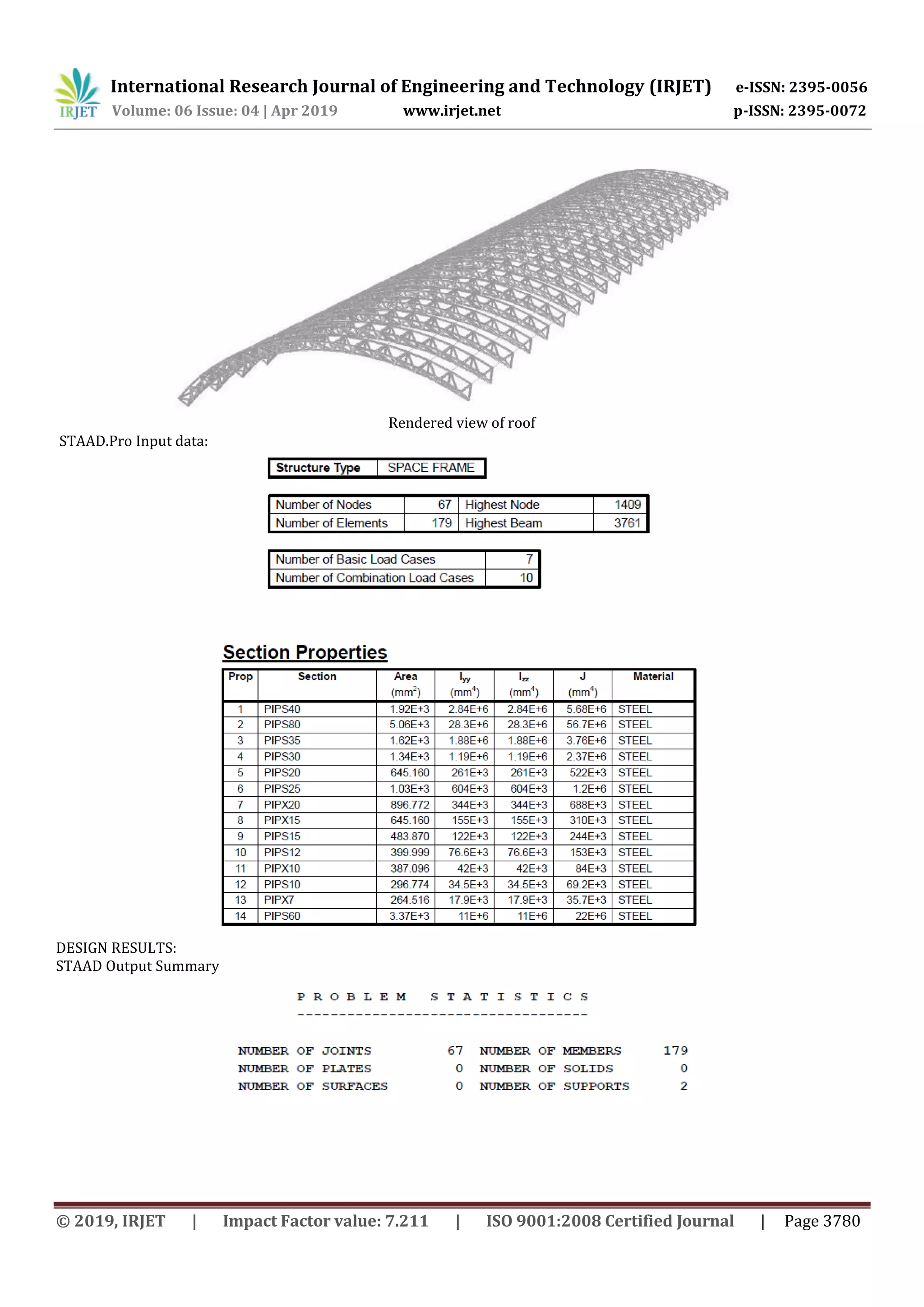
1) The document discusses the design and analysis of a space truss roof using STAAD.Pro software. A space truss is a 3D structural system made of linear elements arranged so that forces are transferred in 3 dimensions. 2) The space truss roof analyzed has a curved arch shape spanning 21.5m and length of 52m. Dead, live, and wind loads were calculated and applied in STAAD.Pro. 3) STAAD.Pro was used to analyze the space truss and output bending moment, shear force, and deflection diagrams. STAAD.Pro confirms whether the structure is safe for given loads and recommends member dimensions. The analysis demonstrated STAAD


![project [Autobots].pptxhfhjbjkkijhhhhhhhhhhhyy](https://cdn.slidesharecdn.com/ss_thumbnails/projectautobots-250122061534-039dfed1-thumbnail.jpg?width=640&height=640&fit=bounds)


