
Recommended
Recommended
More Related Content
Similar to Lecture4-Overney-NanoParticle-Synthesis.pdf
Similar to Lecture4-Overney-NanoParticle-Synthesis.pdf (20)
More from SelvaBabu2
More from SelvaBabu2 (8)
Recently uploaded
Recently uploaded (20)
Lecture4-Overney-NanoParticle-Synthesis.pdf
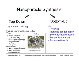
- 1. René Overney / UW Nanothermodynamics and Nanoparticle Synthesis NME 498A / A 2010 Nanoparticle Synthesis via Attrition / Milling Involves mechanical thermal cycles Yields - broad size distribution (10-1000 nm) - varied particle shape or geometry - impurities Application: - Nanocomposites and - Nano-grained bulk materials Via - Pyrolysis - Inert gas condensation - Solvothermal Reaction - Sol-gel Fabrication - Structured Media Top-Down Bottom-Up
- 2. René Overney / UW Nanothermodynamics and Nanoparticle Synthesis NME 498A / A 2010 Bottom – Up Synthesis Phase Classification: I. Gas (Vapor) Phase Fabrication: Pyrolysis, Inert Gas Condensation, …. II. Liquid Phase Fabrication: Solvothermal Reaction, Sol-gel, Micellar Structured Media Part 1: Nanoparticle Synthesis
- 3. René Overney / UW Nanothermodynamics and Nanoparticle Synthesis NME 498A / A 2010 Bottom – Up Synthesis Part 1: Nanoparticle Synthesis Phase Classification: I. Gas (Vapor) Phase Fabrication: Pyrolysis, Inert Gas Condensation, …. II. Liquid Phase Fabrication: Solvothermal Reaction, Sol-gel, Micellar Structured Media
- 4. René Overney / UW Nanothermodynamics and Nanoparticle Synthesis NME 498A / A 2010 Homogeneous Condensation Part 1: Nanoparticle Synthesis E.E. Finney, R.G. Finke / J. Coll. Inter. Sci. 317 (2008) 351–374 Cluster free energy: ΔGV Driving Force: ΔGV Bulk free energy difference between old and new phase CS CL * CL Concentration: CL * … Solution in Equilibrium CL … Supersaturated Solution CS … Solid phase G, Gibbs Free Energy γ π π 2 3 4 3 4 r G r G v * + Δ − = Δ negative volume term positive surface term
- 5. René Overney / UW Nanothermodynamics and Nanoparticle Synthesis NME 498A / A 2010 Growth Steps and Limitations Part 1: Nanoparticle Synthesis • Steps – Generation of growth species (e.g., reduction from minerals) – Diffusion from bulk to the growth surface – Adsorption – Surface growth ( growth modes) 1 2 3 4 5 6 7 8 9 10 VM Growth Modes: SK FM ( ) ∞ − = Δ μ μ μ n 0 number of monolayers • Limitation – Diffusion-limited growth – Size-limited (Oswald ripening) – Transport-limited growth
- 6. René Overney / UW Nanothermodynamics and Nanoparticle Synthesis NME 498A / A 2010 Vapor Phase Growth Part 1: Nanoparticle Synthesis Growth rate of vapor condensation: Δp = pV – pe ξ... condensation coefficient (between 0 and 1) ANP ... surface area of condensate (nanoparticle NP) m .... mass of gas molecule kB .... Boltzmann constant, and T … absolute temperature Driving force: pressure difference Δp pV ….instantaneous vapor pressure Pe …. local equilibrium pressure at the growing cluster ; T mk p A R B NP π ξ 2 Δ = NP NP d A π 4 = Spherical NP: Flux from gas kinetic theory
- 7. René Overney / UW Nanothermodynamics and Nanoparticle Synthesis NME 498A / A 2010 Mechanism and Effectiveness Part 1: Nanoparticle Synthesis – Vapor Phase Synthesis (i) precursor vaporization (typically involves a catalyst) (ii) nucleation, and (iii) growth stage Effectiveness demands: - simple process - low cost - continuous operation - high yield Aerosol Spray Methods (e.g., Spray Pyrolysis)
- 8. René Overney / UW Nanothermodynamics and Nanoparticle Synthesis NME 498A / A 2010 Vapor Phase Synthesis Methods Part 1: Nanoparticle Synthesis Discussed are: • Pyrolysis (Spray Pyrolysis) • Inert Gas Condensation (Chemical Vapor Deposition) inert gas inlet Tube Furnace (~500-1000 oC) HC Gas (CnHm) inert gas inlet Tube Furnace (~500-1000 oC) HC Gas (CnHm) Spray pyrolysis is the aerosol process that atomizes a solution and heats the droplets to produce solid particles
- 9. René Overney / UW Nanothermodynamics and Nanoparticle Synthesis NME 498A / A 2010 Spray Pyrolysis Part 1: Nanoparticle Synthesis – Vapor Phase Synthesis F. Iskandar, Adv. Powder Techn. 20 (2009) 283 production of droplets and their dispersion into the gas can be use only as a dryer or also as a reactor solid particle growth within droplet
- 10. René Overney / UW Nanothermodynamics and Nanoparticle Synthesis NME 498A / A 2010 Spray Pyrolysis Part 1: Nanoparticle Synthesis – Vapor Phase Synthesis F. Iskandar, Adv. Powder Techn. 20 (2009) 283 Atomizer Type Furnace Type Precipitator Type
- 11. René Overney / UW Nanothermodynamics and Nanoparticle Synthesis NME 498A / A 2010 Spray Pyrolysis Part 1: Nanoparticle Synthesis – Vapor Phase Synthesis Droplet Evolution Evaporation Precipitation Drying Decomposition Sintering Messing et al, J. Am. Ceram. Soc., 1993 If the solute concentration at the center of the drop is less than the equilibrium saturation of the solute at the droplet temperature, then precipitation occurs only in that part of the drop where the concentration is higher than the equilibrium saturation, i.e., surface precipitation.
- 12. René Overney / UW Nanothermodynamics and Nanoparticle Synthesis NME 498A / A 2010 Spray Pyrolysis Part 1: Nanoparticle Synthesis – Vapor Phase Synthesis Precipitation Control Che et al, J. Aer. Sci., 1998 Messing et al, J. Am. Ceram. Soc., 1993
- 13. René Overney / UW Nanothermodynamics and Nanoparticle Synthesis NME 498A / A 2010 Spray Pyrolysis: Ga(NO3)3 and GaN Part 1: Nanoparticle Synthesis – Vapor Phase Synthesis Goal: Fabricate GaO3 with - narrow size distribution, and - homogeneous composition Ga(NO3)3 + H2O and LiCl GaN nanoparticles of 23.4 I 1.7 nm diameter T. Ogi et al., Adv. Powder Technology 20 (2009) 29
- 14. René Overney / UW Nanothermodynamics and Nanoparticle Synthesis NME 498A / A 2010 Spray Pyrolysis: Porous Silica NP Part 1: Nanoparticle Synthesis – Vapor Phase Synthesis F. Iskandar / Advanced Powder Technology 20 (2009) 283 Pyrolysis: Generate droplet mixtures of “Primary Particles” with Polymer Particles
- 15. René Overney / UW Nanothermodynamics and Nanoparticle Synthesis NME 498A / A 2010 Porous Silica NP Application: Colloidal Damper Part 1: Nanoparticle Synthesis – Vapor Phase Synthesis Hydraulic Damper (oil is working fluid, energy is dissipated via orifice flow) Colloidal Damper Hydrophobized porous silica particle (outside and inside) suspended in water as the working fluid Advantage: Little heat generation in colloidal damper. C.V. Suciu et al., J. Coll. Interf. Sci., 259 (2003) 62.
- 16. René Overney / UW Nanothermodynamics and Nanoparticle Synthesis NME 498A / A 2010 Inert Gas Condensation (IGC) Part 1: Nanoparticle Synthesis – Vapor Phase Synthesis F. Iskandar, Adv. Powder Techn. 20 (2009) 283 Entails the evaporation of a course substance in an inert gas atmosphere. Evaporation Sources Cold Finger Methods: - Physical Vapor Deposition (PVD) (no catalytic interaction) - Chemical Vapor Deposition (CVD) (with catalytic interaction) Catalytic Surface inert gas inlet Tube Furnace (~500-1000 oC) HC Gas (CnHm)
- 17. René Overney / UW Nanothermodynamics and Nanoparticle Synthesis NME 498A / A 2010 Coalescence and Agglomeration Part 1: Nanoparticle Synthesis – Vapor Phase Synthesis One of the big challenges in condensation growth is that the particles coalesce and agglomerate. A solution proposed: Use of a gas jet stream. A jet stream of carrier gas positioned above the evaporation sites is used to carry away the metal vapor. Utilize that carrier gas vapor mixture cools downstream Continuous Particle growth (nucleation, condensation and coagulation)
- 18. René Overney / UW Nanothermodynamics and Nanoparticle Synthesis NME 498A / A 2010 Liquid Phase Synthesis Methods Part 1: Nanoparticle Synthesis The liquid phase fabrication entails a wet chemistry route. Methods: • Solvothermal Methods (e.g. hydrothermal) • Sol-Gel Methods • Synthesis in Structure Media (e.g., microemulsion)
- 19. René Overney / UW Nanothermodynamics and Nanoparticle Synthesis NME 498A / A 2010 Mechanism and Effectiveness Part 1: Nanoparticle Synthesis – Liquid Phase Synthesis (i) precursor solution (typically involves a catalyst) (ii) nucleation, and (iii) growth stage Effectiveness demands: - simple process - low cost - continuous operation - high yield Sol-Gel and Solvothermal Synthsis
- 20. René Overney / UW Nanothermodynamics and Nanoparticle Synthesis NME 498A / A 2010 Solvothermal Synthesis Part 1: Nanoparticle Synthesis – Liquid Phase Synthesis • Precursors are dissolved in hot solvents (e.g., n-butyl alcohol) - Solvent other than water can provide milder and friendlier reaction conditions If the solvent is water then the process is referred to as hydrothermal method. Example: TiO2 Nanocrystallites Precursor: Titanium n-butoxide Precursor solution with butyl alcohol Autoclave X.F. Yang et al., Euro. J. Inorganic Chem., 2229 (2006).
- 21. René Overney / UW Nanothermodynamics and Nanoparticle Synthesis NME 498A / A 2010 Sol-Gel Processing Part 1: Nanoparticle Synthesis – Liquid Phase Synthesis - Creation of Sol (solid particles in solution) - Followed by the following two generic sol-gel processes (assuming as a precursor a metal alkoxide MOR): hydrolysis: −MOR + H2O −MOH + ROH condensation: −MOH + ROM− −MOM− + ROH or −MOH + HOM− −MOM− + H2O Ex.: Si(OR)4 + 4 H2O → Si(OH)4 + 4 R-OH (OR)3–Si-OH + HO–Si-(OR)3 → [(OR)3Si–O–Si(OR)3] + H-O-H (OR)3–Si-OR + HO–Si-(OR)3 → [(OR)3Si–O–Si(OR)3] + R-OH Condensation towards network of siloxanes
- 22. René Overney / UW Nanothermodynamics and Nanoparticle Synthesis NME 498A / A 2010 Sol-Gel Steps: Part 1: Nanoparticle Synthesis – Liquid Phase Synthesis • Formation of stable sol solution • Gelation via a polycondensation or polyesterification reaction • Gel aging into a solid mass. causes contraction of the gel network, also (i) phase transformations and (ii) Ostwald ripening. • Drying of the gel to remove liquid phases. Can lead to fundamental changes in the structure of the gel. • Dehydration at temperatures as high as 8000 oC, used to remove M-OH groups for stabilizing the gel, i.e., to protect it from rehydration. • Densification and decomposition of the gels at high temperatures (T 8000 oC), i.e., to collapse the pores in the gel network and to drive out remaining organic contaminants
- 23. René Overney / UW Nanothermodynamics and Nanoparticle Synthesis NME 498A / A 2010 Synthesis in Structured Medium Part 1: Nanoparticle Synthesis – Liquid Phase Synthesis Influence Growth Kinetics by Imposing Constraints in Form of Matrices: • Zeolites • Layered Solids • Molecular Sieves • Micelles/Microemulsions • Gels • Polymers • Glasses Ex.: Mixing of two Microemulsion carrying metal salt and reducing agent Intermicellar interchange process via coalescence (rate limiting) (much slower than diffusion: 10 μs and 1 ms I. Capek, Adv. Coll. Interf. Sci. 110 (2004) 49
- 24. René Overney / UW Nanothermodynamics and Nanoparticle Synthesis NME 498A / A 2010 NP Systems: Unique Properties Part 1: Nanoparticle Synthesis Optics: Electronics: Catalysis: Drug Delivery: Sensors: Coatings: High- or low refractive index Unique density of state High reactivity Controlled delivery High sensitivity Increased material strength Ultralow and high adhesion High impact on composite and fluidic systems.
- 25. René Overney / UW Nanothermodynamics and Nanoparticle Synthesis NME 498A / A 2010 Nanofluids: High Thermal Conductivity Part 1: Nanoparticle Synthesis – Unique Properties Nanofluids: Nanoparticle suspension increase of conductivity k up to 60-70% Maxwell Model : ( ) ( ) ⎟ ⎟ ⎠ ⎞ ⎜ ⎜ ⎝ ⎛ − − + − + + = f p f p f p f p f nf k k k k k k k k k k φ φ 2 2 2 Such classical models cannot account for increased conductivity in nanofluids. kp , kp ….particle and fluid thermal conductivity, φ .…particle free volume fraction fluid le nanopartic k k f nf =
- 26. René Overney / UW Nanothermodynamics and Nanoparticle Synthesis NME 498A / A 2010 Nanofluids: High Thermal Conductivity Part 1: Nanoparticle Synthesis – Unique Properties Classical models cannot account for increased conductivity in nanofluids as they lack information about: • Particle size and surface energy • Particle dispersion and clustering • Brownian motion of the particles • Liquid layering (entropy reduction) • …. ( ) ⎟ ⎟ ⎠ ⎞ ⎜ ⎜ ⎝ ⎛ − + = p f p B f nf r r d T k c k k φ φ πη 1 2 1 2 D.H. Kumar et al., Phys. Rev. Lett. 93 (2004) 4301) Dynamic Model (based on kinetic theory and Fourier’s Law) considers Brownian motion and particle size:
- 27. René Overney / UW Nanothermodynamics and Nanoparticle Synthesis NME 498A / A 2010 Nanofluids: Conduction Models Part 1: Nanoparticle Synthesis – Unique Properties Murshed argues: • Most of the recently developed models only include one or two postulated mechanisms of nanofluids heat transfer. • Moreover, these models were not validated with a wide range of experimental data. • There is, therefore a need to develop more comprehensive models, which are based on the first principle, and can explicitly explain the enhanced thermal conductivity of nanofluids. • Particles size, particle dispersions and clustering should be taken into account in the model development for nanofluids. S.M.S. Murshed et al. / Applied Thermal Engineering 28 (2008) 2109–2125
- 28. René Overney / UW Nanothermodynamics and Nanoparticle Synthesis NME 498A / A 2010 Strain in Nanoparticles Part 1: Nanoparticle Synthesis – Unique Properties High surface energy (tension) causes strain in the material Isotropic stress: σ = 1/3 P σ stress [GPa] ε strain [] E (Young’s Modulus) E σ ε = P Nearest Atom Distance γ…. Surface Tension, r …. Particle Radius P = 2γ/r …. Laplace Pressure Pressure caused by interfacial tension: r Er E P 1 3 2 3 1 ∝ = = γ ε
- 29. René Overney / UW Nanothermodynamics and Nanoparticle Synthesis NME 498A / A 2010 Bulk Crystal and Heterostructure Growth Part 1: Nanoparticle Synthesis Nanotechnology needs: Ultrahigh Quality and Purity E.g., Crystalline Silicon: impurity levels 0.1 ppb (1 in 1010) Three Step Process to obtain Polycrystalline Silicon: SiO2 + 2C Si + 2CO Si + 3HCl HSiCl3 + H2 + impurities HSiCl3 + H2 2Si + 6HCl additional reduction reactions with dry hydrochloric acid to drive out impurities final step: hydrogen conversion reaction of trichlorosilane using amorphous carbon electrodes in submerged arc furnace and carbon in the form of mineral carbon, petroleum coke, charcoal, wood-chips
- 30. René Overney / UW Nanothermodynamics and Nanoparticle Synthesis NME 498A / A 2010 Fabrication of Silicon in Nanoelectronics Part 1: Nanoparticle Synthesis – Bulk Crystal and Heterostructure Growth Polycrystalline silicon conversion into single crystal Si ingots: - poly-Si crushed in a crucible in clean room and melted - Convective steams within the melt due to temperature gradients are suppressed by big magnetic fields. - Dopants added to the melt at this point. - A seed crystal is inserted and slowly withdrawn (mm/s) under rotational motion to assure homogeneity, - Via mechanical processes wafers are obtained from the single-crystal ingot. Czochralski method: Yields doped single crystal Si silicon melt seed Si crystal mm/s Source: http://www.tf.uni-kiel.de/matwis/amat/elmat_en/kap_6/illustr/i6_1_1.html
- 31. René Overney / UW Nanothermodynamics and Nanoparticle Synthesis NME 498A / A 2010 Fabrication of Multilayered Crystals Part 1: Nanoparticle Synthesis – Bulk Crystal and Heterostructure Growth Methods excellently suited for heterostructure growth: - Chemical Vapor Deposition (CVD) - Molecular beam epitaxy (MBE) Solution Injection Carrier Gas Evaporator Gas Inlet Low Pressure Reactor Substrate IR Heating Vent Precursor Product Schematic of one of many CVD setups E.g. for silicon layer growth on silicon wafer with dopants: SiCl4 + 2H2 Si + 4HCl
- 32. René Overney / UW Nanothermodynamics and Nanoparticle Synthesis NME 498A / A 2010 Heteroepitaxial Crystal Growth Modes Part 1: Nanoparticle Synthesis – Bulk Crystal and Heterostructure Growth Wetting: γ1 γ2 + γ12 Δ γ ≡ γ2 + γ12 −γ1 0 “Poor wetting” γ1 γ2 + γ12 Three Growth Modes for Heteroepitaxial Growth: • Frank-van der Merwe (FM) (“layer-by-layer” growth) • Volmer-Weber (VW) (“island” growth), and • Stranski-Krastanow (SK) (combined “layer-by-layer and island” growth) Surface Energies: γ1 … substrate γ2 … epilayer γ12 ... interfacial energy FM Δ γ ≡ γ2 + γ12 −γ1 0 dominating interaction VW, SK
- 33. René Overney / UW Nanothermodynamics and Nanoparticle Synthesis NME 498A / A 2010 Epilayer (Film) Growth Part 1: Nanoparticle Synthesis – Bulk Crystal and Heterostructure Growth Chemical Energy of nth monolayer: ( ) ( ) [ ] γ μ γ γ γ μ μ μ μ Δ + = − + + = + = ∞ ∞ Σ ∞ 2 1 12 2 2 a n a n ∞ μ γ μ Δ = Σ 2 a surface chemical potential, bulk chemical potential of the adsorbate material a … area occupied by an atom ( ) 1 12 2 γ γ γ γ − + = Δ n ( ) ⎩ ⎨ ⎧ ≤ − = Δ ≡ Δ ∞ growth VM growth FM ; ; n a 0 0 2 μ μ γ μ ⎩ ⎨ ⎧ ≤ growth VM growth FM ; ; 0 0 equivalent to the chemical potential difference of the nth layer and bulk Surface energy increases for FM growth (and vice versa)
- 34. René Overney / UW Nanothermodynamics and Nanoparticle Synthesis NME 498A / A 2010 Epilayer Pseudomorphic Growth Part 1: Nanoparticle Synthesis – Bulk Crystal and Heterostructure Growth Chemical Energy of nth monolayer with interfacial stress: thickness dependent interfacial stress or difference ( ) ( ) [ ] * * * a n a E n γ μ γ γ γ μ μ μ Δ + = − + + = Δ + = ∞ ∞ ∞ 2 1 12 2 2 ( ) n * 12 γ * γ Δ ( ) ( ) ( ) ( ) ⎩ ⎨ ⎧ + − ≈ − = Δ ∞ n n n ' n E e d des des * ε ε ϕ ϕ μ μ desorption energy of an adsorbate atom from a wetting layer of the same material the desorption energy of an adsorbate atom from the substrate ΔE*, “adhesion energy between misfitting crystals” des ϕ des ' ϕ εd εe the per atom misfit dislocation energy the atom homogeneous strain energy,εe heteroepitaxial homoepitaxial ( ) ( ) ( ) ( ) [ ] n n n ' n a E e d des des * * ε ε ϕ ϕ μ μ γ + + − = − = Δ = Δ ∞ 2
- 35. René Overney / UW Nanothermodynamics and Nanoparticle Synthesis NME 498A / A 2010 Chemical Potential and Growth Modes Part 1: Nanoparticle Synthesis – Bulk Crystal and Heterostructure Growth 1 2 3 4 5 6 7 8 9 10 VM Growth Modes: SK FM ( ) ∞ − = Δ μ μ μ n number of monolayers 0 des des ' ϕ ϕ I. Adhesive forces exceed cohesive forces and weak interfacial mismatch: Frank-van der Merwe Growth (FM) (Layer-by-layer growth: chemical potential increases with increasing layer number) for larger mismatch Stranski-Krastanov Growth (SK) (three growth regimes Combined layer-by-layer and island” growth) II. Cohesive forces exceed adhesive forces Volmer-Weber Growth (VM); i.e., decreasing chemical portential with layer number Island growth des des ' ϕ ϕ ΔE*