Download to read offline
![Estimation of ultimate load by Chin’s Method
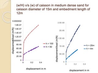
• w/H versus w is plotted
The equation of the straight line can be represented as
w/H = C1 w + C2 (1)
• ultimate load Hu is then equal to
(H)ult = 1/C1 (2)
by Substituting equation (1) in (2) we get
H = [(h)ult w] / [w + (H)ult C2]](https://image.slidesharecdn.com/deformationbehaviourofsuctioncaissonfoundations-220917152850-3d5bd4fd/85/Deformation-Behaviour-of-Suction-Caisson-Foundations-ppt-11-320.jpg)
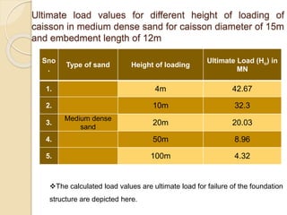
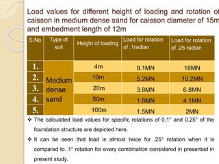
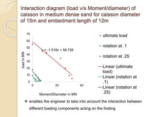
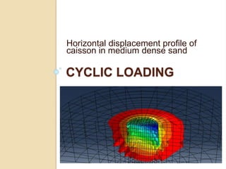
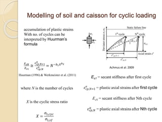
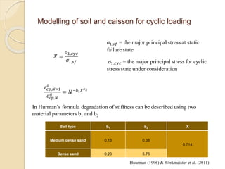
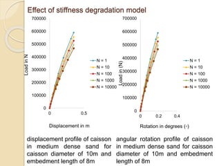
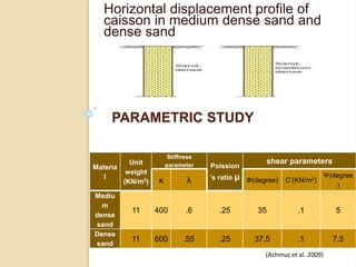
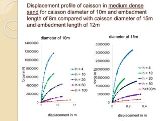


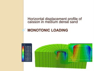
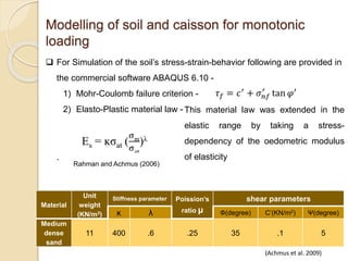
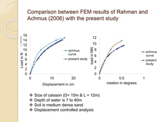
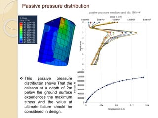
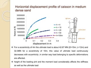
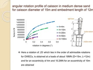
This document summarizes a study on the horizontal load-deformation behavior of suction caisson foundations. The study used finite element modeling in ABAQUS to simulate the behavior of caisson foundations in sandy soils under monotonic and cyclic loading conditions. Key findings included: (1) load capacity decreased with increased loading height and eccentricity, (2) maximum stresses occurred near the mid-depth of the caisson, and (3) stiffness degraded nonlinearly with increasing number of load cycles due to accumulated plastic strains. Parametric analyses looked at the effects of caisson diameter, soil type, and loading conditions. Conclusions focused on developing design methods for predicting load-moment interactions and capacity. Future work could consider clay soils


